


模板缓冲
介绍 (Introduction)
The trendy thing in real-time rendering these days is ray-tracing. However, traditional rasterization hasn’t disappeared, and it won’t in the near future. I recommend this blog post on the subject: A hybrid rendering pipeline for realtime rendering: (When) is raytracing worth it?
如今,实时渲染中的流行趋势是光线追踪 。 但是,传统的栅格化还没有消失,并且在不久的将来也不会消失。 我推荐有关此主题的博客文章: 用于实时渲染的混合渲染管道:(何时)光线跟踪值得吗?
I find that one of the most neglected elements in the rasterization pipeline is the Stencil Buffer. To get an idea of how neglected it is, I’ve checked the number of appearances of the stencil buffer in the approximately 1000 pages of “Real-Time Rendering”[1]: it appears just 5 times, and there are no more than 4 paragraphs dedicated to it. At least for me, it’s hard to get my head around the stencil buffer because it’s not fully programmable, so I tend to avoid using it. You can only configure it, and to do so you have to think of Boolean algebra, but in 3D.
我发现栅格化管道中最被忽略的元素之一是模板缓冲区 。 为了了解它是如何被忽略的,我检查了大约1000页“实时渲染” [1]中模版缓冲区的出现次数:它仅出现5次,并且不超过专门针对它的4个段落。 至少对我来说,很难完全绕过模板缓冲区,因为它不是完全可编程的,因此我倾向于避免使用它。 您只能对其进行配置,并且必须这样做,但必须考虑布尔代数,但要使用3D。
This blog post is an attempt to demystify the stencil buffer. I will briefly review the rendering pipeline, to see where the stencil sits, and then explain how the stencil works. I will use an example application in WebGL that we use to detect volume intersections, and explain the steps to convert the algorithm in my head to a tabular format that can be used to configure the stencil.
这篇博客文章试图揭开模板缓冲区的神秘面纱。 我将简要回顾渲染管线,以查看模板位于何处,然后解释模板的工作方式。 我将在WebGL中使用一个示例应用程序,该示例程序用于检测体积相交,并说明将我头脑中的算法转换为可用于配置模具的表格格式的步骤。
栅格化渲染管道 (The Rasterization Rendering Pipeline)
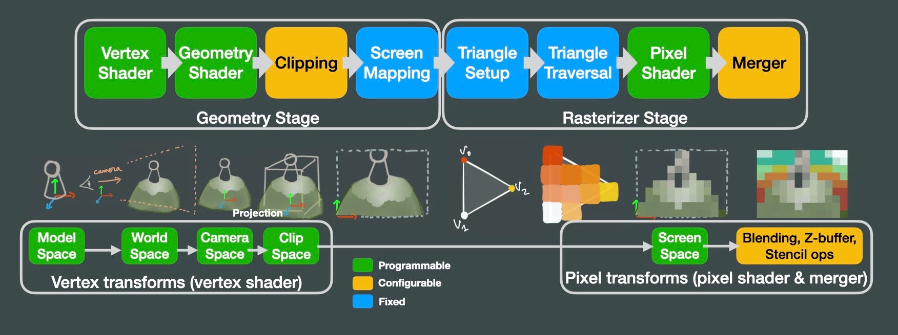
Virtually every GPU implements a rendering pipeline like the one above. In the middle row I tried to illustrate the transformations that we apply to our models until they become an image on the screen. In the vertex shader, we receive the triangles that make up the surface of our 3D model. Then, our vertex shader will apply a series of matrix multiplications to those triangles to convert from the model space (origin of coordinates centered around the model), to world space (origin of coordinates in the world origin), and then to camera space (origin of coordinates in the camera). Then, we apply a projection transform (perspective or orthographic), so the camera frustum becomes a unit cube. Whatever is outside that unit cube gets clipped, and mapped to screen coordinates. Then the rasterizer converts those triangles into pixels, interpolating color values between vertices. Then we can apply operations per pixel in
 最低0.47元/天 解锁文章


 4341
4341


 被折叠的 条评论
为什么被折叠?
被折叠的 条评论
为什么被折叠?
 到【灌水乐园】发言


