From:https://developer.nvidia.com/content/basics-gpu-voxelization
What Can You Do With Voxelization?
A voxel representation of a scene has spatial data as opposed to the conventional rasterization view (as stored in a render target) which just has a slice of depth value. A voxelized scene can be easily traversed spatially and you can access data from coarse world locations. This enables rendering techniques which require spatial data such as indirect illumination, more convincing ambient occlusion and volumetric light shafts. Also it is also possible to utilize voxel information to make gameplay decisions. An example would be to cast a ray in the voxel grid to check a visibility. If you have ideas which could make use of coarse spatially organized information from your scene, voxel representation is worth considering.
What is GPU Voxelization?
The basic concept of GPU Voxelization to use GPU shaders to convert a scene composed of triangle meshes into a regular voxel grid representation.
The process for doing this is pretty straightforward.
- First you transform the vertex positions of a primitive into a regular eulerian grid (the “voxel grid”) coordinate system in the Vertex Shader stage.
- Then you rasterize the transformed primitive using a viewport of the same dimensions as one of the 2D projections of the voxel grid. Because the orthogonal viewport frustum can cover the voxel grid exactly, and a rasterized pixel position in the render target and its depth value correspond X, Y and Z components of the voxel grid.
- Then, finally, map each rasterized fragment onto one or several voxels and write some data into those voxels in the Pixel Shader stage. Note that the data is written to a 3D texture which is bound as a UAV buffer, not a 2D conventional render target. You don’t need a render target at all, but you need to set a proper viewport that is aligned with a face of the voxel grid.
The following pictures describe this process visually.

Figure 1: Orthogonal projection view frustum aligned to fit the voxel grid you will use to voxelize the scene.

Figure 2: A pixel location on the render target and its depth value correspond X, Y and Z of the voxel grid
Oh No! Cracks During Voxelization!
However you voxelize continuous primitive planes, there are cases that fail to voxelize correctly and have holes or slits in the result. The following two pictures are the results of voxelizations which were done with identical primitives and voxel grid.
The one which was done with horizontal camera direction got correct-looking results and the primitive was sufficiently voxelized. However, the other was done with vertical camera direction and is not sufficiently voxelized, having cracks between voxels. This is because the shader runs based on pixels covered in the viewport. Thus, if the slope of the primitive being drawn is steep with respect to the view direction, you can get cracks.

Figure 3: Voxelization camera from the right facing left.

Figure 4: Voxelization cameralooking down on the scene
More specifically, whether or not you’ll get cracks depends on the depth gradient of the primitive being rendered. This can be calculated with ddx(depth), ddy(depth) in the pixel shader. If either of these gradients exceeds 1.0, then the voxelized plane will have “cracks” in a direction perpendicular to the depth direction.
To fix this issue, primitives need to be rendered from an axis that presents the largest face area with respect to the camera. In other words, from a camera direction selected from the X, Y and Z axes according to the face normal. Since the different faces of a single mesh are all differently oriented, this requires rendering the mesh from potentially 3 different directions; but we don’t need 3 render passes. Since the X, Y and Z axes are orthogonal each other, we just need to swizzle the X, Y and Z components to change the projection direction, and this can be done in the geometry shader stage per primitive. Then, the pixel shader restores the coordinate components according to the information that comes from the GS. In that fashion we can avoid the issue of missing voxels caused by high depth gradients.

Figure 5: Three potential directions to project a primitive.

Figure 6: Y axis is best here. This get chosen in GSper primitive.
What? More Holes!
Selecting the proper projection direction has fixed “cracks”. However, by breaking up the projection directions we can introduce a new problem of “holes”. The following picture will describe it in 2D. Please think these three different colored line segments as three adjoining primitives on a single mesh.

Figure 7: 3 primitives of a single mesh. Blue is projected in Z, Red is projected in X
In order to project the largest area, we’ve chosen the projection plane in the GS. Blue colored segments are projected in the Z axis direction and the red segment is projected in the X axis direction. This results in the following pixel shader invocations.

Figure 8: Blue shading on pixels represent "covered" pixels. Note the gap where the pixel is not covered by any primitive.
Generally, a pixel shader is invoked when a primitive covers the center of a pixel. When the red segment is projected in the X direction, none of the pixel centers were covered, so it wasn’t rasterized at all. This issue wouldn’t happen if all of the primitives were projected in a single direction. Changing the projection direction causes this issue. To fix this issue, we need to change the rasterization rules to consider a pixel covered if any part of it is touched by a primitive. This type of rasterization is called Conservative Rasterization. There is a great article covering how to perform this manually (by expanding primitive edges) in GPU Gems 3: [GPU Gems: Chapter 42 Conservative Rasterization]. As a quick summary, the technique expands primitive edges to ensure all pixels touched are covered. We’ll also talk about a possibly better alternative at the end of this blog post.
Also, finally, should note that if you are running the new Maxwell base chip set (or higher) you can make use of actual official artifact-free conservative raster by using NVAPI. Here’s the link. [Don't be conservative with Conservative Rasterization] If you use the hardware conservative raster supported by Maxwell GPUs, then you need not worry about the artifacts from expanding primitive edges, and a lot of the following sections can be ignored (as they are covering how to deal with edge extension artifacts!).
Extra Voxels Generated By Expanded Primitive Edges For Conservative Rasterization
Finally, we’ve got a sufficiently complete voxelization. However, there is still an issue we have left. If you used the technique of expanding the primitive’s edges in GS to get us Conservative Rasterization, some extra pixels are shaded. Yellow pixels in the following picture are the extra pixels not covered by the primitive, but still shaded. Especially for thin triangles, this method will produce a fair number of extra pixel shader calls.

Figure 9: Green are initial covered pixels. Red are desired pixels covered by conservative raster. Yellow are undesired pixels mistakenly covered.

Figure 10: This bunny has some spaghetti on his ears!
In the following section, we will add processes to check voxel-primitive intersections to cull unwanted voxels.
Voxel-Primitive Intersections In A Single Pixel
The following picture illustrates a primitive (red plane) intersecting multiple voxels in the depth direction, which means in the same pixel.

Figure 11: The red plane intersects 3 voxels in depth direction.
The light purple triangle’s ddx(depth) and ddy(depth) are indeed just 1.0, and the red plane is parallel to it. These planes have the maximum depth gradient possible in the process of voxelization. The red plane intersects front, center and rear voxels. Since these are in the same pixel, the Pixel Shader will be invoked once for all of them. If we apply the conservative rule in the depth direction, we must check for intersections between the primitive’s plane and these 3 voxels in the Pixel Shader. To do that, we can calculate the depth gradient in the Geometry Shader and pass it to the Pixel Shader, or compute the depth gradient in the Pixel Shader with the ddx and ddy functions. Then, we check for intersections between the primitive’s plane and these 3 voxels, using the gradient value and the depth value at the center of the pixel (which should be retrieved as a pixel’s depth value in the Pixel Shader).When you intersect a voxel with a primitive, you think of the voxel as being a certain shape, such as a box or sphere. This shape, called the intersection target, will determine topological conditions of the voxelized primitive. If you’re interested in intersection targets, you should refer to A Topological Approach to Voxelization [Samuli Laine, 2013]. In this section, we use the entire box of a voxel as an intersection target. To check intersection between a voxel and a primitive, there are some generic intersection tests, such as the Separating Axis Theorem; we will use a method that can separate its workload between the GS and PS. The process consists of two parts. The first one is an AABB (Axis Aligned Bounding Box) test and the second one is an edge-voxel condition test. If a voxel passes these two tests then the primitive intersects that voxel and the voxel is covered.
AABB Test
The voxel’s AABB is defined by the regular voxel grid. The primitive’s AABB can be found from the maximum and minimum X, Y and Z of its vertex coordinates. To achieve better workload balancing, a primitive’s AABB should be calculated in the GS, then the voxel-primitive AABB test should be done in the PS. The test is passed if the voxel bounding box intersects the primitive’s AABB.
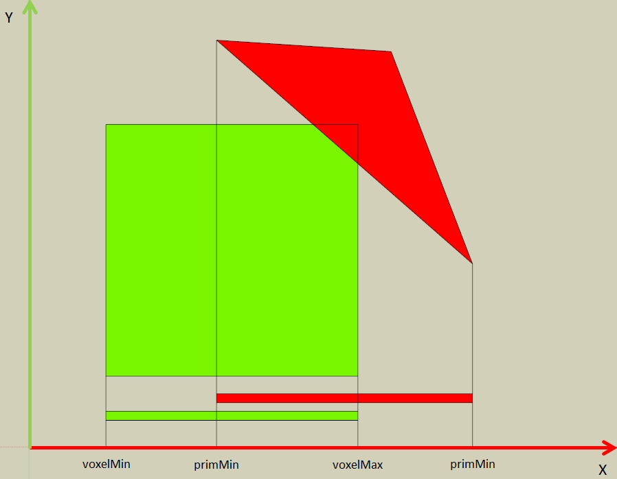
Figure 12: AABB testing with a triangle (red) and a voxel (green).
The following pseudocode illustrates this process.
In GS
void getAABB(in float3 v1, in float3 v2, in float3 v3, out float3 primMin, out float3 primMax) {
primMin = min(min(v1.x, v2.x), v3.x);
primMax = max(max(v1.x, v2.x), v3.x);
}
In PS
float3 voxelPosf = float3(SV_Position.xy, SV_Position.z * voxelResolution_Z);
float3 voxelMin = voxelPosf – 0.5;
float3 voxelMax = voxelPosf + 0.5;
if ((primMax.x – voxelMin.x) * (primMinX.x – voxelMax.x) >= 0.0 ||
(primMax.y – voxelMin.y) * (primMinX.y – voxelMax.y) >= 0.0 ||
(primMax.z – voxelMin.z) * (primMinX.z – voxelMax.z) >= 0.0)
discard;
Edge-Voxel Condition Test
Checking the edge-voxel condition is done in in each of the three axis-aligned planes. For each edge, we calculate the signed distance from the edge to the voxel’s vertices. The maximum signed distance value across all the voxel’s vertices is used for the test. In the following picture, the edge with the red normal vector is checked with the vertex colored red, which is the voxel corner with the maximum signed distance along the red normal. The other two edges (green and blue) are checked similarly. If all of the calculated signed distances are positive, this test is passed.
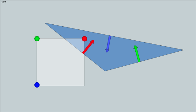
Figure 13: Edge-Voxel condition testing.
The following code snippet shows the edge-voxel condition tests in the pixel shader.
//calculate edge vectors in voxel coordinate space
float3 e0 = IN.VoxPos[1] - IN.VoxPos[0];
float3 e1 = IN.VoxPos[2] - IN.VoxPos[1];
float3 e2 = IN.VoxPos[0] - IN.VoxPos[2];
float3 planeNormal = cross(e0, e1);
// for testing in XY plane projection
{
float isFront = -sign(planeNormal.z);
float2 eNrm[3];
eNrm[0] = float2(e0.y, -e0.x) * isFront;
eNrm[1] = float2(e1.y, -e1.x) * isFront;
eNrm[2] = float2(e2.y, -e2.x) * isFront;
float2 an[3];
an[0] = abs(eNrm[0]);
an[1] = abs(eNrm[1]);
an[2] = abs(eNrm[2]);
// calculate signed distance offset from a voxel center
// to the voxel vertex which has maximum signed
// distance value.
float3 eOfs;
eOfs.x = (an[0].x + an[0].y) * voxelExtentH;
eOfs.y = (an[1].x + an[1].y) * voxelExtentH;
eOfs.z = (an[2].x + an[2].y) * voxelExtentH;
// calculate signed distance of each edges.
float3 ef;
ef.x = eOfs.x –
dot(IN.VoxPos[0].xy - voxelCenter.xy , eNrm[0]);
ef.y = eOfs.y –
dot(IN.VoxPos[1].xy - voxelCenter.xy , eNrm[1]);
ef.z = eOfs.z –
dot(IN.VoxPos[2].xy - voxelCenter.xy , eNrm[2]);
// test is passed if all of signed distances are positive.
if (ef.x < 0 || ef.y < 0 || ef.z < 0)
return false;
}
// tests in YZ and ZX plane projection are also done as well.
GPU Voxelization Using MSAA
As we described above, to manually implement conservative rasterization on the GPU, we extended the edges of primitives in the Geometry Shader, which consumes many GPU cycles. In this section, we describe another GPU voxelization approach using MSAA, which does not require expansion of the primitive to get conservative rasterization.
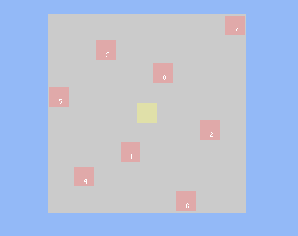
Figure 14: 8xMSAA sample locations
Without MSAA, the pixel shader is only invoked for pixels whose centers are covered by a primitive, as we previously discussed.
However, when enabling 8xMSAA, the pixel shader is invoked if any of the subsamples are covered by a primitive. This subsample region covers most of the pixel in 8xMSAA. Additionally, the pixel shader is invoked only once, regardless how many subsamples are covered in a pixel. This is really close to actual conservative rasterization, as long as you have sufficient count and spacing of subsample points. So by using MSAA we don’t need to expand the primitive’s edges, there are no extra pixel shader calls, and the geometry shader is much simpler! This also enables us to skip those primitive-voxel intersection tests which we needed to do to remove the extra voxels!
However, this method is not genuine conservative rasterization. Primitives which lie in-between subsamples still have a possibility not to be voxelized properly. Additionally, you need to create an MSAA render target to bind, which slightly increases the memory cost in vidmem (probably not that big of a deal). If you can utilize Forced Sample Count in DX11.1, you can enable MSAA rasterization without binding an MSAA render target.
So this is a relatively aggressive method, as it has a possibility to have “holes”, which are avoidable by making sure the voxel grid is fine/high-res enough for the sizes of voxelized primitives.
The following three pictures are examples of pixel shader invocations in different rasterization methods.

Figure 15: Conventional Rasterization

Figure 16: Conservative Raster via edge extension

Figure 17: Conservative Raster via MSAArender target
The following three pictures are also examples of voxelizations without voxel-primitive intersection tests.
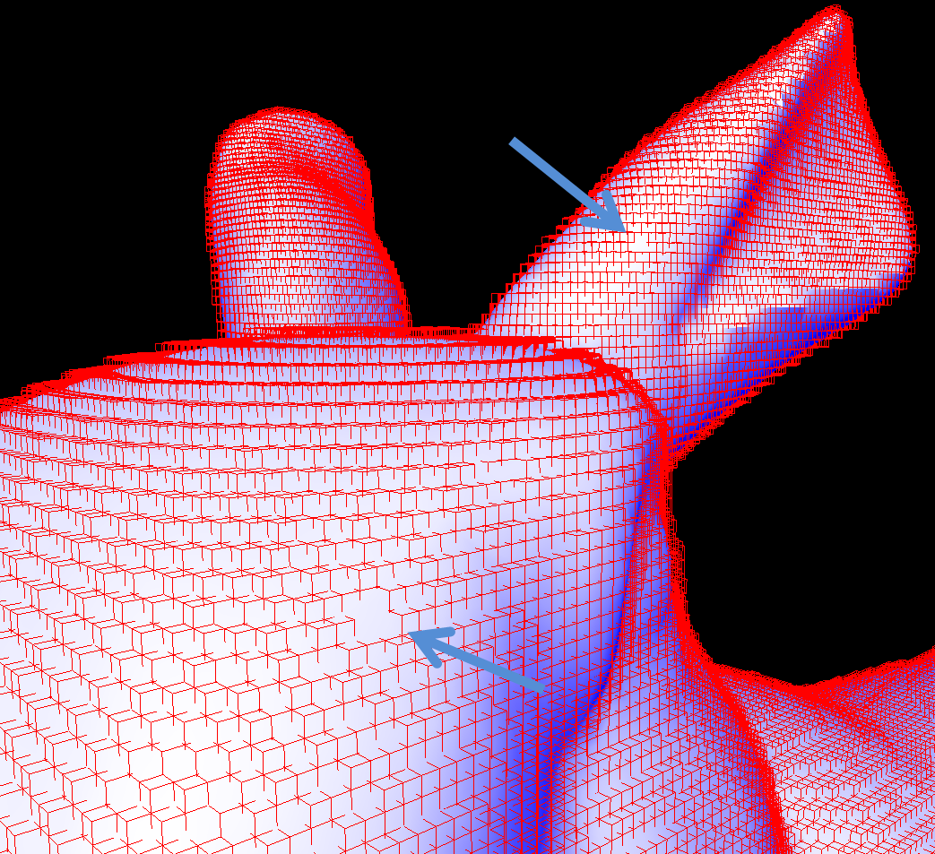
Figure 18: Conventional Rasterization. Cracks due to high gradients.
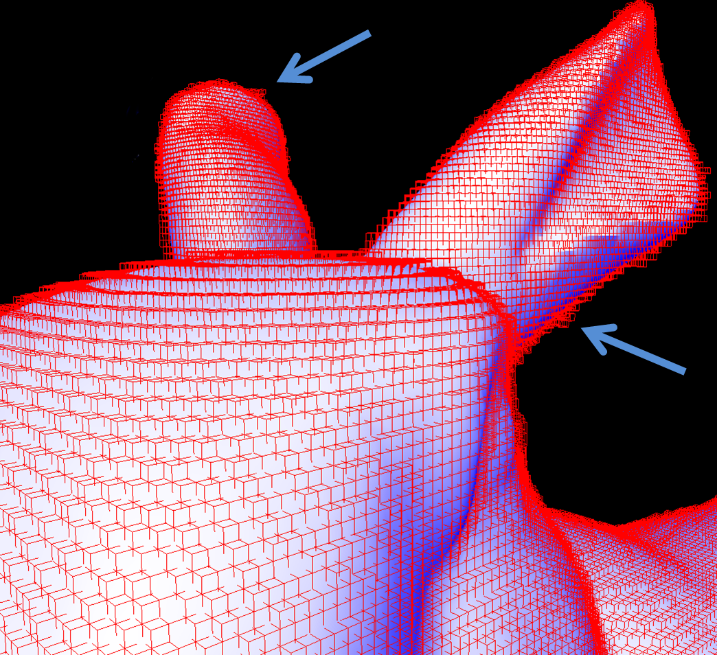
Figure 19: Conservative Rasterization with edge extension. Cracks from conventional rasterization are fixed, but we can see extra voxels.
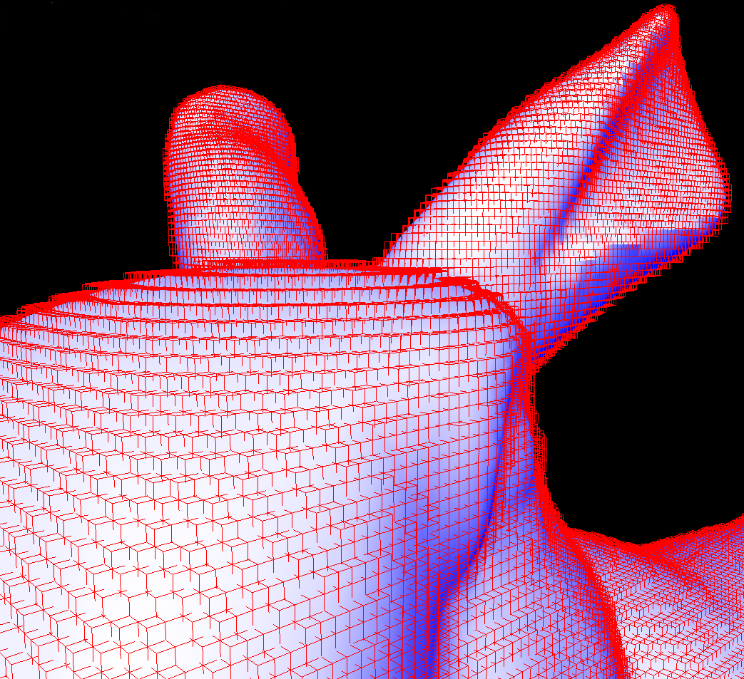
Figure 20: Conservative rasterization with MSAA render target. No holes or redundant voxels
Conclusion
In this article, we have described the basics of GPU voxelization. You can choose methods as you like to fit your purpose. Currently, MSAA voxelization is reasonable in most cases, but you might need to implement an accurate method as a reference. Also, if you are running on Maxwell or higher GPU architecture then you should definitely use the official conservative rasterization functions and you can skip edge extension issues.
References
An Accurate Method for Voxelizing Polygon Meshes[Huang et al. 98]
Fast Parallel Surface and Solid Voxelization on GPUs [Michael et al. 10]
Octree-Based Sparse Voxelization Using the GPU Hardware Rasterizer [Cyril et al. 11]
A Topological Approach to Voxelization [Samuli Laine, 2013]
GPU Gems 2 Chapter 42. Conservative Rasterization


 618
618

 被折叠的 条评论
为什么被折叠?


