


This is the fourth part of a tutorial series about rendering. The previous part was about combining textures. This time we'll look at how to compute lighting.
Unity dynamically merges small meshes together, to reduce draw calls. The meshes of the spheres are too large for this, so they aren't affected. But the cubes are fair game.
To merge meshes, they have to converted from their local space to world space. Whether and how objects are batched depends, among other things, on how they are sorted for rendering. As this conversion affects the normals as well, this is why we see the colors change.
Besides dynamic batching, Unity can also do static batching. This works differently for static geometry, but also involves a conversion to world space. It happens at build time.
Except for dynamically batched objects, all our normals are in object space. But we have to know the surface orientation in world space. So we have to transform the normals from object to world space. We need the object's transformation matrix for that.
Unity collapses an object's entire transformation hierarchy into a single transformation matrix, just like we did in part 1. We could write this as O=T1T2T3…O=T1T2T3… where TT are the individual transformations and OO is the combined transformation. This matrix is known as the object-to-world matrix.
While we have normalized vectors again, they look weird for objects that don't have a uniform scale. That's because when a surface gets stretched in one dimension, its normals don't stretch in the same way.
Scaling X, both vertices and normals by ½.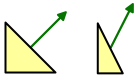
When the scale is not uniform, it should be inverted for the normals. That way the normals will match the shape of the deformed surface, after they've been normalized again. And it doesn't make a difference for uniform scales.
Scaling X, vertices by ½ and normals by 2.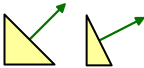
We described object's transformation matrix as O=T1T2T3…O=T1T2T3… but we can be more specific that than. We know that each step in the hierarchy combines a scaling, rotating, and positioning. So each TT can be decomposed into SRPSRP.
This means that O=S1R1P1S2R2P2S3R3P3…O=S1R1P1S2R2P2S3R3P3… but let's just say O=S1R1P1S2R2P2O=S1R1P1S2R2P2 to keep it short.
Because normals are direction vectors, we don't care about repositioning. So we can shorten it further to O=S1R1S2R2O=S1R1S2R2 and we only have to consider 3 by 3 matrices.
We want to invert the scaling, but keep the rotations the same. So we want a new matrix N=S−11R1S−12R2N=S1-1R1S2-1R2.
How do inverse matrices work?
The inverse of a matrix MM is written as M−1M-1. It is a matrix that will undo the operation of another matrix when they are multiplied. Each is the inverse of the other. So MM−1=M−1M=IMM-1=M-1M=I.
To undo a sequence of steps, you have to perform the inverse steps in reverse order. The mnemonic for this involves socks and shoes. This means that (AB)−1=B−1A−1(AB)-1=B-1A-1.
In the case of a single number xx, its inverse is simply 1x1x, because xx=1xx=1. This also demonstrates that zero has no inverse. Neither does every matrix have an inverse.
We're working with scaling, rotating, and repositioning matrices. As long as we're not scaling by zero, all these matrices can be inverted.
The inverse of a reposition matrix is made by simply negating the XYZ offset in it's fourth column.
⎡⎢ ⎢ ⎢ ⎢⎣100x010y001z0001⎤⎥ ⎥ ⎥ ⎥⎦−1=⎡⎢ ⎢ ⎢ ⎢⎣100−x010−y001−z0001⎤⎥ ⎥ ⎥ ⎥⎦[100x010y001z0001]-1=[100-x010-y001-z0001]
The inverse of a scaling matrix is made by inverting its diagonal. We only need to consider the 3 by 3 matrix.
⎡⎢⎣x000y000z⎤⎥⎦−1=⎡⎢ ⎢ ⎢⎣1x0001y0001z⎤⎥ ⎥ ⎥⎦[x000y000z]-1=[1x0001y0001z]
Rotation matrices can be considered one axis at a time, for example around the Z axis. A rotation by zzradians can be undone by simply rotating by −z-z radians. When you study the sine and cosine waves, you'll notice that sin(−z)=−sinzsin(-z)=-sinz and cos(−z)=coszcos(-z)=cosz. This makes the inverse matrix simple.
⎡⎢⎣cosz−sinz0sinzcosz0001⎤⎥⎦−1=⎡⎢⎣coszsinz0−sinzcosz0001⎤⎥⎦[cosz-sinz0sinzcosz0001]-1=[coszsinz0-sinzcosz0001]
Notice that the rotation inverse is the same as the original matrix flipped across its main diagonal. Only the signs of the sine components changed.
Besides the object-to-world matrix, Unity also provides an object's world-to-object matrix. These matrices are indeed inverses of each other. So we also have access to O−1=R−12S−12R−11S−11O-1=R2-1S2-1R1-1S1-1.
That gives use the inverse scaling that we need, but also gives us the inverse rotations and a reversed transformation order. Fortunately, we can remove those unwanted effects by transposing the matrix. Then we get (O−1)T=N(O-1)T=N.
What is the transpose of a matrix?
The transpose of a matrix MM is written as MTMT. You transpose a matrix by flipping its main diagonal. So its rows become columns, and its columns become rows. Note that this means that the diagonal itself is unchanged.
⎡⎢⎣123456789⎤⎥⎦T=⎡⎢⎣147258369⎤⎥⎦[123456789]T=[147258369]
Like inversion, transposing a sequence of matrix multiplications reverses its order. (AB)T=BTAT(AB)T=BTAT. This makes sense when working with matrices that aren't square, otherwise you could end up with invalid multiplications. But it's true in general, and you can look up the proof for it.
Of course flipping twice gets you back where you started. So (MT)T=M(MT)T=M.
Why does transposing produce the correct matrix?
First, notice that R−1=RTR-1=RT, as observed above.
This leads to O−1=R−12S−12R−11S−11=RT2S−12RT1S−11O-1=R2-1S2-1R1-1S1-1=R2TS2-1R1TS1-1.
Now let's transpose (O−1)T=(S−11)T(RT1)T(S12)T(RT2)T=(S−11)TR1(S−12)TR2(O-1)T=(S1-1)T(R1T)T(S21)T(R2T)T=(S1-1)TR1(S2-1)TR2.
Next, notice that ST=SST=S, because these matrices have zeros everywhere, except along their main diagonal.
This leads to (O−1)T=S−11R1S−12R2=N(O-1)T=S1-1R1S2-1R2=N.
After producing correct normals in the vertex program, they are passed through the interpolator. Unfortunately, linearly interpolating between different unit-length vectors does not result in another unit-length vector. It will be shorter.
So we have to normalize the normals again in the fragment shader.
Diffuse Shading
We see objects that aren't themselves light sources, because they reflect light. There are different ways in which this reflection can happen. Let's first consider diffuse reflection.
Diffuse reflection happens because a ray of light doesn't just bounce off a surface. Instead, it penetrates the surface, bounces around for a bit, gets split up a few times, until it exits the surface again.
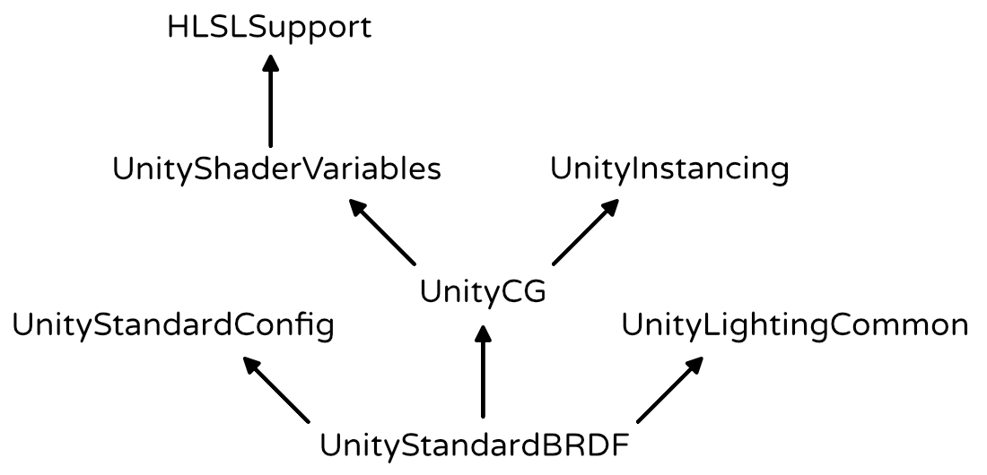
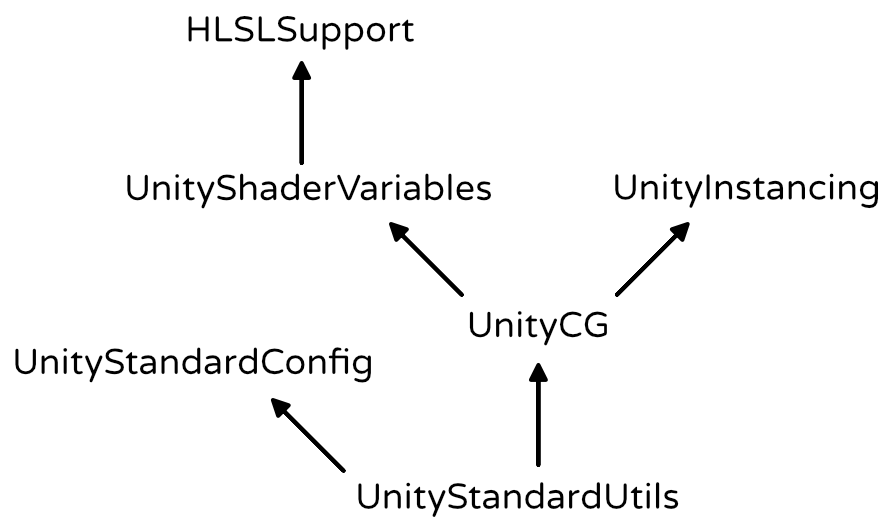
Include file hierarchy, starting at UnityStandardBRDF.
By default, each Unity scene has a light that represents the sun. It is a directional light, which means that it is considered to be infinitely far away. As a result, all its light rays come from exactly the same direction. Of course this isn't true in real life, but the sun is so far away that it is a fair approximation.
How much light is diffusely refected off a surface depends on the angle at which the light ray hits it. Most light is reflected when the surface is hit head-on, at a 0° angle. As this angle increases, the reflections will decrease. At 90°, no light hits the surface anymore, so it stays dark[前面说的角度已经是和法线所形成的夹角了,而不是直观想象中的夹角,还有需要注意的是这个光的方向是反射光的方向,法线的方向就不用说了对吧]. The amount of diffused light is directly proportional to the cosine of the angle between the light direction and the surface normal. This is known as Lambert's cosine law[反射光与法线方向的点乘就是光照影响物体表面的量,这叫做兰伯特余弦定律].
Computing the dot product works when the surface is directed towards the light, but not when it is directed away from it. In that case, the surface would logically be in its own shadow and it should receive no light at all.
We have to use the ForwardBase pass. This is the first pass used when rendering something via the forward rendering path. It gives us access to the main directional light of the scene. It sets up some other things as well, but we'll cover those later.
	Pass {
		Tags {
			"LightMode" = "ForwardBase"
		}

		CGPROGRAM

		…

		ENDCG
	}
The color of the diffuse reflectivity of a material is known as its albedo. Albedo is Latin for whiteness. So it describes how much of the red, green, and blue color channels are diffusely reflected. The rest is absorbed. We can use the material's texture and tint to define this.
Besides diffuse reflections, there are also specular reflections. This happens when light doesn't get diffused after hitting a surface. Instead, the light ray bounces off the surface at and angle equal to the angle at which it hit the surface. This is what causes the reflections that you see in mirrors. Unlike with diffuse reflections, the position of the viewer matters for specular reflections. Only light that ends up reflected directly towards you is visible. The rest goes somewhere else, so you won't see it. 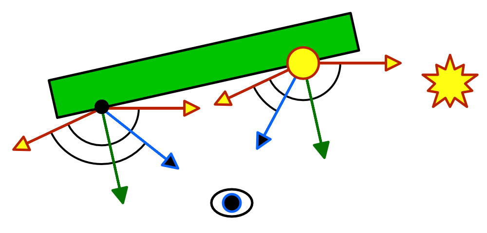
We're currently computing the reflection according to the Blinn reflection model. But the most-often used model is Blinn-Phong. It uses a vector halfway between the light direction and the view direction. The dot product between the normal and the half vector determines the specular contribution. 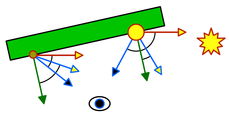
 The UnityStandardBRDF include file defines the convenient DotClamped function.
Metallic Workflow There are basically two kinds of materials that we are concerned with. There are metals, and there are nonmetals. The latter are also known as dielectric materials. Currently, we can create metals by using a strong specular tint. And we can create dielectrics by using a weak monochrome specular. This is the specular workflow.
It would be much simpler if we could just toggle between metal and nonmetal. As metals don't have albedo, we could use that color data for their specular tint instead. And nonmetals don't have a colored specular anyway, so we don't need a separate specular tint at all. This is known as the metallic workflow. Let's go with that.
Physically-Based Shading Blinn-Phong has long been the workhorse of the game industry, but nowadays physically-based shading – known as PBS – is all the rage. And for good reason, because it is a lot more realistic and predictable. Ideally, game engines and modeling tools all use the same shading algorithms. This makes content creation much easier. The industry is slowly converging on a standard PBS implementation.
Unity's standard shaders use a PBS approach as well. Unity actually has multiple implementations. It decides which to used based on the target platform, hardware, and API level. The algorithm is accessible via the UNITY_BRDF_PBS macro, which is defined in UnityPBSLighting. BRDF stands for bidirectional reflectance distribution function. 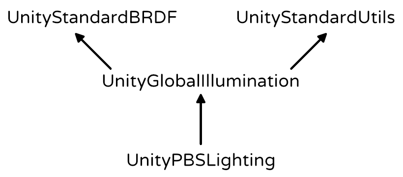
These functions are quite math-intensive, so I won't go into the details. They still compute diffuse and specular reflections, just in a different way than Blinn-Phong. Besides that, there also is a Fresnel reflection component. This adds the reflections that you get when viewing objects at grazing angles. Those will become obvious once we include environmental reflections.
To make sure that Unity selects the best BRDF function, we have to target at least shader level 3.0. We do this with a pragma statement.
Light Structures UnityLightingCommon defines a simple UnityLight structure which Unity shaders use to pass light data around. It contains a light's color, its direction, and an ndotl value, which is the diffuse term. Remeber, these structures are purely for our convenience. It doesn't affect the compiled code.


 689
689

 被折叠的 条评论
为什么被折叠?
被折叠的 条评论
为什么被折叠?
 到【灌水乐园】发言


