


前言
最近在自学计算机图形学,很多教程和书籍里面都提到一个经典的学习办法就是自己写一个软渲染器。不过在实际动手的时候却发现,网上关于图形学的资料实在是太零碎了,每一个知识点都能找到许多讲解文章,真正写的时候却发现还是有蛮多坑是踩了才知道。于是决定一边写一边在知乎上面开个坑记录一下,供后来者参考。本文尽量保证读者顺着做下来就能直接运行,不需要再去对比源码找漏了哪里。本人也是初学者,难免出现错误,欢迎指正。
主要参考资料:
learnopengl-cn ,很详细的OpenGL学习资料,本文就是模拟这里面提到的渲染管线
《Unity shader入门精要》,女神写的书,虽然是基于Unity的但是原理讲得很好
前置知识:线性代数中的向量、矩阵等相关知识,看这里 数学知识
编写语言:C++
文中的图片除了实机运行图其他都是网上搜集的,如有侵权,告知我就会删除。
需求分析
什么是软渲染器?软渲染器能实现什么功能?区别与硬渲染器,软渲染器就是由CPU完成整个渲染流程,生成帧缓冲,然后显示到屏幕上。
我们编写的软渲染器,接受的输入是顶点(包含位置、颜色、纹理坐标、法向量),输出是一帧的颜色缓冲,或者理解为一张图片。将帧缓冲写入文件或者用一些API在屏幕上显示出来,就完成了整个渲染过程。
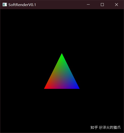
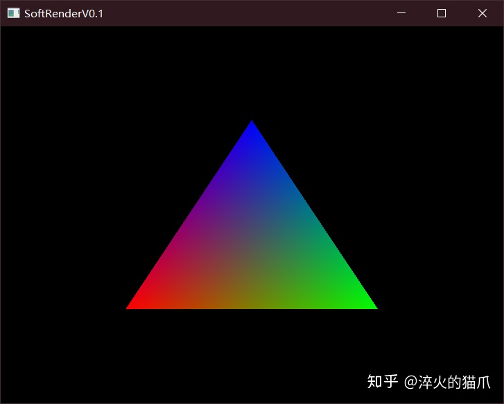
例: 输入三个顶点 ,得到显示结果
A(-0.5,-0.5,0) 颜色 (255, 0, 0)
B(0,0.5,0) 颜色(0,255,0)
C(0.5,-0.5,0) 颜色(0,0,255)
环境配置
C++本身是没有显示图形的库的,要将渲染好的图形展示出来需要第三方库的支持,比如Qt、MFC或者是OpenGL。我这里选用了LearnOpenGL里面的GLFW+GLAD做图形显示,使用GLM做数学库。
照着LearnOpenGL的环境配置,先显示出一个只有背景颜色的窗口,然后最后在渲染循环中使用glDrawPixels渲染我们的缓冲数组就可以了。
GLFW+GLAD环境配置
正式动手
我们先实现画二维图形的功能,因为三维图形最终也是要投影到屏幕空间上变成二维的。显示图像使用的是glDrawPixels函数,该函数读取一个地址的内存数据,按指定的格式在屏幕上画一张图,参数如下:
void glDrawPixels( int width, int height, GLenum format, GLenum type, const void *pixels )
我们使用一个unsigned char数组(颜色值是0-255),每个像素四位( RGBA ),那么应该是这样调用
glDrawPixels( Width, Height, GL_RGBA, GL_UNSIGNED_BYTE, data );
每一帧需要生成一个 屏幕分辨率 宽*高*4 的帧缓冲数组,为此我们封装一个类来管理
class FrameBuffer {
public:
	int Width, Height;
	std::vector<unsigned char> colorBuffer;
	~FrameBuffer() = default;

	FrameBuffer(const int &w = 800, const int &h = 600) {
		Width = w;
		Height = h;
		//RGBA
		colorBuffer.resize(w*h * 4,0);
	}
	void Resize(const int &w, const int &h) {
		Width = w;
		Height = h;
		colorBuffer.resize(w*h * 4,0);
	}

	void ClearColorBuffer(const glm::vec4 &color) {
	        unsigned char * p = colorBuffer.data();
		for (int i = 0; i < Width*Height * 4; i += 4) {
			*(p + i) = color.r;
			*(p + i + 1) = color.g;
			*(p + i + 2) = color.b;
			*(p + i + 3) = color.a;
		}
		/*
		int length = Width * Height * 4;
		for (int i = 0; i < length; i+=4) {
			colorBuffer[i] = 255;
			colorBuffer[i + 1] = 0;
			colorBuffer[i + 2] = 0;
			colorBuffer[i + 3] = 0;
		}*/
	}
	void WritePoint(const int &x, const int &y, const glm::vec4 &color) {
		if (x < 0 || x >= Width || y < 0 || y >= Height)
			return;
		int xy = (y * Width + x);
		colorBuffer[xy * 4] = color.r;
		colorBuffer[xy * 4 + 1] = color.g;
		colorBuffer[xy * 4 + 2] = color.b;
		colorBuffer[xy * 4 + 3] = color.a;
	}
};
这里有一个大坑,vector直接使用下标访问赋值的速度非常感人,生成图像时帧数很低,但是使用自带的assign函数进行复制速度又很快,在网上查了半天,应该是VS在debug模式下做的安全检查之类的。查看assign源代码之后,将下标访问换成了直接访问地址赋值,果然快了很多。
顶点数据
顶点是我们输入的数据结构,为此也写一个类来进行管理。一个顶点包含的数据有:模型坐标、顶点颜色、顶点法向、纹理坐标。注意位置坐标使用的是四维齐次坐标,在模型空间和世界空间的坐标都是x,y,z加上恒为1的w,所以要用四维向量。
class Vertex {
public:
	glm::vec4 position;
	glm::vec4 color;
	glm::vec2 texcoord;
	glm::vec3 normal;

	Vertex() = default;
	~Vertex() = default;

	Vertex(
		const glm::vec4 & _pos,
		const glm::vec4 & _color,
		const glm::vec2 & _tex,
		const glm::vec3 & _normal
	) :
		position(_pos), color(_color), texcoord(_tex), normal(_normal) {}
	Vertex(
		const glm::vec3 & _pos,
		const glm::vec4 & _color = glm::vec4(0, 0, 0, 0),
		const glm::vec2 & _tex = glm::vec2(0, 0),
		const glm::vec3 & _normal = glm::vec3(0, 0, 1)
	) :
		position(_pos,1.0f), color(_color), texcoord(_tex), normal(_normal) {}
	Vertex(const Vertex &v) :position(v.position), color(v.color), texcoord(v.texcoord), normal(v.normal) {}
};
渲染管线
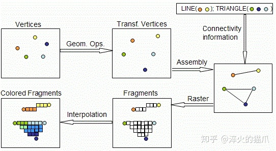
输入和输出都有了,现在就要着手搭建渲染管线了。通常的OpenGL渲染管线是这样的:
- 输入顶点数据和图元类型(点、直线、三角形等基本图元)
- 顶点着色器对顶点进行处理,将坐标变换到世界坐标,计算纹理坐标和顶点颜色等,输出到中间结构体(v2f)
- 对v2f进行图元装配过程,也就是为每个三角形指定顶点数据与索引
- 将顶点变换到摄像机的观察空间
- 进行投影,将顶点变换到裁剪空间
- 进行裁剪和面剔除工作,将看不见的图元进行裁剪,剔除背向面,减少后续计算量
- 执行齐次除法,将顶点变换到NDC(标准设备坐标)
- 执行视口变换,最终将顶点转换到屏幕坐标(从三维变成二维)
- 光栅化,计算图形在屏幕上最终覆盖的像素点
- 用顶点数据插值,在像素点位置生成新的v2f
- 逐像素运行片段着色器,进行纹理采样、光照计算等,输出该点最终颜色值(RGBA)
- 执行透明度测试->模板测试->深度测试,丢弃掉一些片元
- 执行混合操作
我们现在有了顶点数据,下一步要执行顶点着色器,因此需要定义数据结构接收输出,并作为片段着色器的输入
class V2F {
public:
	glm::vec4 worldPos;
	glm::vec4 windowPos;
	glm::vec4 color;
	glm::vec2 texcoord;
	glm::vec3 normal;

	V2F() = default;
	~V2F() = default;
	V2F(
		const glm::vec4 & _wPos,
		const glm::vec4 & _pPos,
		const glm::vec4 & _color,
		const glm::vec2 & _tex,
		const glm::vec3 & _normal
	) :
		worldPos(_wPos), windowPos(_pPos), color(_color), texcoord(_tex), normal(_normal) {}
	V2F(const V2F &v) :
		worldPos(v.worldPos), windowPos(v.windowPos), color(v.color), texcoord(v.texcoord), normal(v.normal) {}

        static V2F lerp(const V2F &v1, const V2F &v2, const float &factor) {
		V2F result;
		result.windowPos = Lerp(v1.windowPos, v2.windowPos, factor);
		result.worldPos = Lerp(v1.worldPos, v2.worldPos, factor);
		result.color = Lerp(v1.color, v2.color, factor);
		result.normal = Lerp(v1.normal, v2.normal, factor);
		result.texcoord = Lerp(v1.texcoord, v2.texcoord, factor);
		return result;
	}
};
v2f类需要实现一个重要功能就是插值,以网格的几个顶点插值生成整个面的片元,为此新建一个Math.h文件,在其中定义如下插值函数,实现两个顶点之间的线性插值
glm::vec4 Lerp(const glm::vec4 &v1,const glm::vec4 &v2,float factor) {
	return (1.0f - factor) * v1 + factor * v2;
}
glm::vec3 Lerp(const glm::vec3 &v1, const glm::vec3 &v2, float factor) {
	return (1.0f - factor)*v1 + factor * v2;
}
glm::vec2 Lerp(const glm::vec2 &v1, const glm::vec2 &v2, float factor) {
	return (1.0f - factor)*v1 + factor * v2;
}
着色器
现在我们需要用顶点着色器来对顶点进行处理了。因为现在只需要画二维图形,所以三个变换矩阵都置为单位矩阵,实际上等于没做变换直接输出。片段着色器也是直接将调用点的颜色进行输出了。
class Shader {

public:
	Shader() {
		ModelMatrix = glm::mat4(1.0f);
		ViewMatrix = glm::mat4(1.0f);
		ProjectMatrix = glm::mat4(1.0f);
	}
	~Shader() = default;
private:
	glm::mat4 ModelMatrix;
	glm::mat4 ViewMatrix;
	glm::mat4 ProjectMatrix;

public:
	V2F VertexShader(const Vertex &a2v) {
		V2F o;
		o.worldPos = ModelMatrix * a2v.position;
		// PVM*v
		o.windowPos = ProjectMatrix * ViewMatrix * o.worldPos;
		o.color = a2v.color;
		o.normal = a2v.normal;
		o.texcoord = a2v.texcoord;
		return o;
	}
        //现在直接输出点的颜色
	glm::vec4 FragmentShader(const V2F &v) {
		glm::vec4 color;
		color = v.color;
		return color;
	}

	void setModelMatrix(const glm::mat4 &model) {
		ModelMatrix = model;
	}
	void setViewMatrix(const glm::mat4 &view) {
		ViewMatrix = view;
	}
	void setProjectMatrix(const glm::mat4 &project) {
		ProjectMatrix = project;
	}
};
在主函数中,我们定义三个顶点,用于画出我们的第一个三角形。由于OpenGL的NDC的坐标范围是[-1,1),而我们目前并没有做任何的坐标变换,因此我们直接定义NDC下的顶点坐标
Shader shader;
FrameBuffer FrontBuffer(SCR_WIDTH,SCR_HEIGHT);

Vertex V1(glm::vec3(-0.5,-0.5,0),glm::vec4(255,0,0,0));
Vertex V2(glm::vec3(0.5,-0.5,0),glm::vec4(0,255,0,0));
Vertex V3(glm::vec3(0,0.5,0),glm::vec4(0,0,255,0));

V2F o1 = shader.VertexShader(V1);
V2F o2 = shader.VertexShader(V2);
V2F o3 = shader.VertexShader(V3);
视口变换
我们得到了处理后的顶点,然而别着急,现在我们还在NDC当中,需要进一步转化为屏幕上像素点的坐标,这就是视口变换。视口变换做的操作是将X,Y坐标从[-1,1)映射到屏幕坐标[0,w)和[0,h)上,同时将原点从屏幕中间移到左下角。注意,在OpenGL中,左下角是原点,右上角是(w,h),而DirectX中左上角才是原点。在我们的Math.h中存入视口矩阵,该矩阵是一个缩放+平移的矩阵
// glm 的矩阵是行矩阵,而一般我们用的都是列矩阵,所以存放的时候要转置
// 行矩阵做变换是  v * M  ,列矩阵是 M * v
// ox oy 是原点的坐标
// x坐标乘以w/2 ,y坐标乘以h/2,整体向左下平移
// Vp = [  w/2 ,   0  ,  0  , ox+w/2 ,
//	    0  ,  h/2 ,  0  , oy+h/2 ,
//          0  ,   0  ,  1  ,   0    ,
//          0  ,   0  ,  0  ,   1   ]
glm::mat4 GetViewPortMatrix(int ox, int oy, int width, int height) {

	glm::mat4 result = glm::mat4(1.0f);
	result[0][0] = width / 2.0f;
	result[3][0] = ox + (width / 2.0f);
	result[1][1] = height / 2.0f;
	result[3][1] = oy + (height / 2.0f);
	return result;
}
在上面的循环中,我们对顶点继续进行视口变换,得到屏幕坐标
//在前面加入
glm::mat4 ViewPortMatrix = GetViewPortMatrix(0,0,SCR_WIDTH,SCR_HEIGHT);

......

o1.windowsPos = ViewPortMatrix * o1.windowsPos;
o2.windowsPos = ViewPortMatrix * o2.windowsPos;
o3.windowsPos = ViewPortMatrix * o3.windowsPos;
光栅化
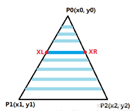
接下来需要计算我们的三角形覆盖了哪些屏幕像素,这里使用经典的扫描线算法。其思想很简单,从三角形最上面的点开始往下逐步画横线,两个交点之间的区域就是覆盖的区域。
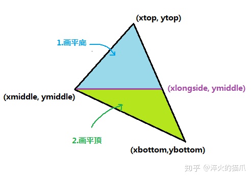
朝向下侧的三角形原理也是一样的,只不过是对称过来了。有了这两种三角形,不难发现任意三角形都能最多分为一个平顶和一个平底三角形,于是我们得到一般三角形的光栅化方法:
- 根据三个顶点的y坐标判定是否有两个相等,有则判断是平底还是平顶三角形,直接画
- 找到y值在中间的点,划分出上下两个三角形,画两个
        //扫描线填充算法
	//对任意三角形,分为上下两个平底三角形填充
	void ScanLineTriangle(const V2F &v1,const V2F &v2,const V2F &v3) {
		std::vector<V2F> arr = { v1,v2,v3 };
		if (arr[0].windowPos.y > arr[1].windowPos.y) {
			V2F tmp = arr[0];
			arr[0] = arr[1];
			arr[1] = tmp;
		}
		if (arr[1].windowPos.y > arr[2].windowPos.y) {
			V2F tmp = arr[1];
			arr[1] = arr[2];
			arr[2] = tmp;
		}
		if (arr[0].windowPos.y > arr[1].windowPos.y) {
			V2F tmp = arr[0];
			arr[0] = arr[1];
			arr[1] = tmp;
		}
		//arr[0] 在最下面  arr[2]在最上面
		//中间跟上面的相等,是底三角形
		if (equal(arr[1].windowPos.y, arr[2].windowPos.y)) {
			DownTriangle(arr[1], arr[2], arr[0]);
		}//顶三角形
		else if (equal(arr[1].windowPos.y, arr[0].windowPos.y)) {
			UpTriangle(arr[1], arr[0], arr[2]);
		}
		else {
                 //插值求出中间点对面的那个点,划分为两个新的三角形
			float weight = (arr[2].windowPos.y - arr[1].windowPos.y) / (arr[2].windowPos.y - arr[0].windowPos.y);
			V2F newEdge = V2F::lerp(arr[2],arr[0], weight);
			UpTriangle(arr[1],newEdge,arr[2]);
			DownTriangle(arr[1], newEdge, arr[0]);
		}
	}
	void UpTriangle(const V2F &v1, const V2F &v2, const V2F &v3) {
		V2F left, right, top;
		left = v1.windowPos.x > v2.windowPos.x ? v2 : v1 ;
		right = v1.windowPos.x > v2.windowPos.x ? v1 : v2;
		top = v3;
		left.windowPos.x = int(left.windowPos.x);
		int dy = top.windowPos.y - left.windowPos.y;
		int nowY = top.windowPos.y;
		//从上往下插值
		for (int i = dy ; i >= 0; i--) {
			float weight = 0;
			if (dy != 0) {
				weight = (float)i / dy;
			}
			V2F newLeft = V2F::lerp(left,top, weight);
			V2F newRight = V2F::lerp(right,top, weight);
			newLeft.windowPos.x = int(newLeft.windowPos.x);
			newRight.windowPos.x = int(newRight.windowPos.x+0.5);
			newLeft.windowPos.y = newRight.windowPos.y = nowY;
			ScanLine(newLeft, newRight);
			nowY--;
		}
	}
	void DownTriangle(const V2F &v1, const V2F &v2, const V2F &v3) {
		V2F left, right, bottom;
		left = v1.windowPos.x > v2.windowPos.x ? v2 : v1;
		right = v1.windowPos.x > v2.windowPos.x ? v1 : v2;
		bottom = v3;
		int dy =  left.windowPos.y - bottom.windowPos.y;
		int nowY = left.windowPos.y;
		//从上往下插值
		for (int i = 0; i < dy; i++) {
			float weight = 0;
			if (dy != 0) {
				weight = (float)i / dy;
			}
			V2F newLeft = V2F::lerp(left,bottom, weight);
			V2F newRight = V2F::lerp(right,bottom, weight);
			newLeft.windowPos.x = int(newLeft.windowPos.x);
			newRight.windowPos.x = int(newRight.windowPos.x+0.5);
			newLeft.windowPos.y = newRight.windowPos.y = nowY;
			ScanLine(newLeft, newRight);
			nowY--;
		}
	}
	void ScanLine(const V2F &left,const V2F &right) {
		int length = right.windowPos.x - left.windowPos.x;
		for (int i = 0; i < length; i++) {
			V2F v = V2F::lerp(left,right, (float)i / length);
			v.windowPos.x = left.windowPos.x + i;
			v.windowPos.y = left.windowPos.y;
			FrontBuffer.WritePoint(v.windowPos.x, v.windowPos.y, shader.FragmentShader(v));
		}
	}
显示图像
如果你还记得我们是在LearnOpenGL的空白窗口程序上进行的后续开发,那么整个程序现在应该是这个样子
Shader shader;
FrameBuffer FrontBuffer;
int main(){

     ......

    glm::mat4 ViewPortMatrix = GetViewPortMatrix(0,0,SCR_WIDTH,SCR_HEIGHT);
    FrontBuffer.Resize(SCR_WIDTH,SCR_HEIGHT);


    Vertex V1(glm::vec3(-0.5,-0.5,0),glm::vec4(255,0,0,0));
    Vertex V2(glm::vec3(0.5,-0.5,0),glm::vec4(0,255,0,0));
    Vertex V3(glm::vec3(0,0.5,0),glm::vec4(0,0,255,0));

    V2F o1 = shader.VertexShader(V1);
    V2F o2 = shader.VertexShader(V2);
    V2F o3 = shader.VertexShader(V3);

    o1.windowsPos = ViewPortMatrix * o1.windowsPos;
    o2.windowsPos = ViewPortMatrix * o2.windowsPos;
    o3.windowsPos = ViewPortMatrix * o3.windowsPos;


	while (!glfwWindowShouldClose(window))
	{
		processInput(window);

                FrameBuffer.ClearColorBuffer(glm::vec4(0,0,0,0));
                ScanLineTriangle(o1,o2,o3);
                glDrawPixels(SCR_WIDTH, SCR_HEIGHT, GL_RGBA, GL_UNSIGNED_BYTE, FrontBuffer.colorBuffer.data())

              ......
         }
}
运行一下,应该是这个样子,显示出了一个三角形
渲染流程封装
我们成功渲染出了二维图形,不过目前我们的渲染流程对外还是暴露太多了,需要一定的封装。定义一个类来做这个事吧。
class Draw {

private:
	int Width;
	int Height;
	FrameBuffer *FrontBuffer;
	Shader *shader;
	glm::mat4 ViewPortMatrix;
public:
	Draw(const int &w, const int &h) :
		Width(w),Height(h),FrontBuffer(nullptr),shader(nullptr){}
	~Draw(){
		if(FrontBuffer)
			delete FrontBuffer;
		if(shader)
			delete shader;
		FrontBuffer = nullptr;
		shader = nullptr;
	}
	void setModelMatrix(const glm::mat4 &model) {
		shader->setModelMatrix(model);
	}
	void setViewMatrix(const glm::mat4 &view) {
		shader->setViewMatrix(view);
	}
	void setProjectMatrix(const glm::mat4 &project) {
		shader->setProjectMatrix(project);
	}
	void Init() {
		if (FrontBuffer)
			delete FrontBuffer;
		if (shader)
			delete shader;
		ViewPortMatrix = GetViewPortMatrix(0,0,Width,Height);
		FrontBuffer = new FrameBuffer(Width, Height);
		shader = new Shader();
	}
	void Resize(const int& w,const int &h) {
		Width = w;
		Height = h;
		FrontBuffer->Resize(w, h);
		ViewPortMatrix = GetViewPortMatrix(0, 0, w, h);
	}
	void ClearBuffer(const glm::vec4 &color) {
		FrontBuffer->ClearColorBuffer(color);
	}
        void Show() {
		glDrawPixels(Width, Height, GL_RGBA, GL_UNSIGNED_BYTE, FrontBuffer->colorBuffer.data());
	}
        void DrawTriangle(const Vertex &v1,const Vertex &v2,const Vertex &v3){
                V2F o1 = shader.VertexShader(V1);
                V2F o2 = shader.VertexShader(V2);
                V2F o3 = shader.VertexShader(V3);

                o1.windowsPos = ViewPortMatrix * o1.windowsPos;
                o2.windowsPos = ViewPortMatrix * o2.windowsPos;
                o3.windowsPos = ViewPortMatrix * o3.windowsPos;
                ScanLineTriangle(o1,o2,o3);
        }

        //光栅化的函数也放在这里,把里面对FrameBuffer的操作修改一下
        ......

};
这样,我们在主函数里面只需要操纵Draw类便可以了
Draw * dw;
int main(){

     ......

    dw = new Draw(SCR_WIDTH, SCR_HEIGHT);
    dw->Init();

    Vertex V1(glm::vec3(-0.5,-0.5,0),glm::vec4(255,0,0,0));
    Vertex V2(glm::vec3(0.5,-0.5,0),glm::vec4(0,255,0,0));
    Vertex V3(glm::vec3(0,0.5,0),glm::vec4(0,0,255,0));

	while (!glfwWindowShouldClose(window))
	{
		processInput(window);
		glClearColor(0.0f, 0.0f, 0.0f,0.0f);
                dw->ClearBuffer(glm::vec4(0,0,0,0));
                dw->DrawTriangle(V1,V2,V3);
                dw->Show();
              ......
         }
}
总结
费了好一番功夫,终于是完成了图形学的一个HelloWorld程序,难怪学图形学的人这么少呢。不过一路踩下来,还是收获不小的,包括C++的一些新特性、代码的风格等方面都学到了不少,在数学原理方面也终于理解通顺了。下一阶段要开始做3D图形的渲染了,虽然更加复杂,不过框架已经搭好,就可以更专注学习原理和算法方面了。希望这篇文章能够帮到你,如果觉得有帮助请点个赞吧


 104万+
104万+

 被折叠的 条评论
为什么被折叠?
被折叠的 条评论
为什么被折叠?
 到【灌水乐园】发言


