


PT2262是一款很古老的编码芯片,其兼容型号有:SC2262,AD2262,SC2260(需改变匹配电阻)等。
依据其datasheet,PT2262射频模式工作原理:
CODE BITS
A Code Bit is the basic component of the encoded waveform, and can be classified as either an AD (Address/Data) Bit or a SYNC (Synchronous) Bit.
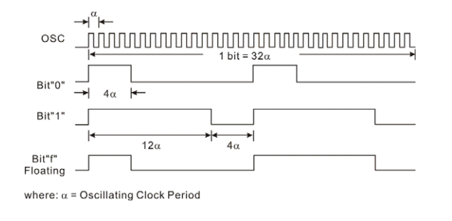
ADDRESS/DATA (AD) BIT WAVEFORM
An AD Bit can be designated as Bit “0”, “1” or “f” if it is in low, high or floating state respectively. One bit waveform consists of 2 pulse cycles. Each pulse cycle has 16 oscillating time periods. For further details, please refer to the diagram below:
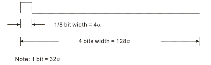
SYNCHRONOUS (SYNC.) BIT WAVEFORM
The Synchronous Bit Waveform is 4 bits long with 1/8 bit width pulse. Please refer to the diagram below:
CODE WORD
A group of Code Bits is called a Code Word. A Code Word consists of 12 AD bits followed by one Sync Bit. The 12 AD bits are determined by the corresponding states of A0 ~ A5 and A6/D5 ~ A11/D0 pins at the time of transmission. When Data Type of PT2262 is used, the address bits will decrease accordingly. For example: In the 3 Data Type where the address has nine (9) bits, the transmitting format is:

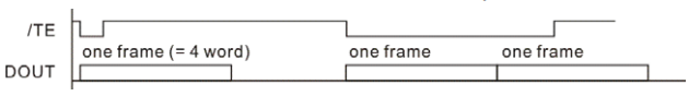
CODE FRAME
A Code Frame consists of four (4) continuous Code Words. When PT2262 detects “0” on the /TE (meaning, the /TE is active “low”), it outputs a Code Frame at DOUT. If /TE is still active at the time the Code Frame transmission ends, T2262 outputs another Code Frame. It should be noted that the Code Frame is synthesized at the time of transmission.
PT2262-IR红外模式工作原理
IR OPERATION
In the IR Type of Operation, the functions are similar to the above descriptions except for the output waveform that has a carrier frequency of 38KHz. Details are as follows(此图0编码错误):
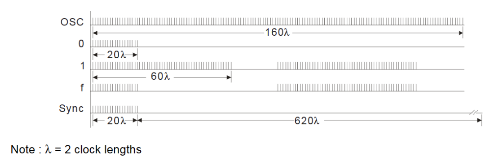
以上需要注意的是,对于后缀为IR的芯片,其输出是没有载波的,例如,输出bit 1,仅仅是60λ高+20λ低+60λ高+20λ低,高电平期间并没有调制波。
CODE BITS
The Code Bits are further modulated with a 38KHz carrier frequency and can be “0”, “1” or “f” bit.
CODE FRAME
Likewise, a Code Frame is made up of Code Words and the format is the same as that of RF Type of Operation,即有4个连续的CODE WORD。
OSCILLATOR
The Oscillator Frequency for the IR Type of Operation is twice the carrier frequency. Thus, the oscillator frequency should be kept at 76 KHz. A 430K ~ 560KΩ oscillator resistor between OSC 1 and OSC 2 pins is recommended. It should be noted that the carrier is a 50% duty cycle frequency.
实际发射:A0-A7地址位+D0-D3数据位+同步信号
对于红外38KHz,测得结果20λ约为320us。计算:λ=16us,clock脉宽为8us,周期16us,即频率62.5KHz(与38KHz的两倍,即76KHz有一定误差)。为了更精确还原38KHz(实际值小于此),建议取值:周期13.15us,则λ取13.15us,20λ取263us.
综上:振荡频率应该是76KHz,振荡电阻是430~560K之间。如果振荡频率是76KHz,根据datasheet说明,其接收频率应该是2.5~8倍该频率,即190~608KHz,对应的电阻小于200K。但对于红外接收来说,由于没有载波,接收频率取76K。
选型:
PT2262-IR,后缀务必带IR,但目前市场上有假货,即用普通PT2262打磨后,重新激光打印成2262-IR。
解码芯片:PT2272-L4,经测试,后缀带M4与PT2262-IR无法很好匹配。
实用匹配电阻选择:
发射:约150-560K,故可用100K固定电阻+500K电位器
接收:约300-450K,可用500K电位器
红外接收选择,宜选择2脚的红外接收管,便宜好用;部分3脚的红外接收管波长不匹配,无法工作,特别是一体的(例如部分HS0038),个别由于本身会产生波形而带来干扰。
3脚(小鼻梁):接收窗口对自己,左右依次:OUT,GND,VCC。
3脚(带平面):接收窗口对自己,左右依次:OUT,VCC,GND。
2脚接收管:上拉10K电阻(缺口相连)后送入NPN三极管,该三极管集电极接5K电阻,另一脚接地(长脚,即反接)。
红外发射管:金属比较多处为阴极(负),1N4148二极管/发光二极管,长脚为正。
若不采用带后缀IR的,(射频),根据官方datasheet,其匹配电阻:
1.2M/200K 发射电阻1.2M时,发射频率约40K,接收若也为40K,则接收电阻可取510K-1M之间
1.5M/270K 发射电阻1.5M时,发射频率约30K,接收若也为30K,则接收电阻可取1M
2.2M/390K 发射电阻2.2M时,发射频率约20K,接收若也为20K,则接收电阻可取1.5M
4.7M/820K 发射电阻4.7M时,发射频率约8KHz,接收若也为800Hz,则接收电阻可取2M
利用Arduino对ESP8266编程,实现对海尔空调的遥控,代码如下:
#include <Arduino.h>
#include <IRremoteESP8266.h>
#include <IRsend.h>
const uint16_t kIrLed = 4;
IRsend irsend(kIrLed);
uint16_t rawData[149] = {3228, 2772,  3246, 4252,  746, 1454,  756, 344,  760, 1438,
  764, 334,  756, 342,  748, 1450,  746, 352,  746, 1454,  760, 340,  764, 1436,  756, 342,
  748, 350,  746, 352,  746, 354,  744, 354,  752, 346,  760, 340,  764, 336,  764, 1434,  748, 350,
  748, 352,  746, 354,  744, 354,  752, 346,  760, 340,  764, 336,  764, 334,  758, 342,  750, 350,
  746, 352,  746, 354,  744, 354,  752, 348,  758, 340,  764, 336,  764, 334,  758, 1440,  748, 1452,
  744, 354,  750, 348,  758, 340,  762, 336,  764, 334,  758, 340,  750, 348,  746, 352,  746, 354,  744, 354,
  770, 328,  778, 322,  780, 1418,  778, 320,  750, 348,  746, 352,  746, 354,  744, 354,  750, 350,  758, 342,
  762, 338,  764, 336,  760, 338,  752, 348,  746, 352,  746, 354,  744, 354,  748, 350,  756, 1442,  762, 1436,
  752, 348,  746, 352,  746, 352,  744, 1454,  756};
void setup() {
  irsend.begin();
}
void loop() {
  irsend.sendNEC(0x11A00AB9);
  delay(1000);
  irsend.sendRaw(rawData, 149, 38);
  delay(1000);
}
需要注意的是,需要增加IRremoteESP8266库:

对于算能MilkV Duo,通过Arduino,模拟实现PT2262-IR功能:
#define GP16 21
#define longt 600
#define shortt 190
#define synct 11935
#define pulse(x) digitalWrite(GP16, HIGH),delayMicroseconds(x)
#define upulse(y) digitalWrite(GP16, LOW),delayMicroseconds(y)
#define bit0 pulse(shortt),upulse(longt),pulse(shortt),upulse(longt)
#define bit1 pulse(longt),upulse(shortt),pulse(longt),upulse(shortt)
#define bitf pulse(shortt),upulse(longt),pulse(longt),upulse(shortt)
#define Sync pulse(shortt),upulse(synct)
#define IRsend(x) for(int j=0;j<4;j++){\
                    for(int i=0;i<12;i++){\
                    switch(x[i]){\
                      case '0':bit0;break;\
                      case '1':bit1;break;\
                      case 'f':bitf;break;\
                      }\
                    }\
                    Sync;\
                  }
//ffffffff0100
uint8_t IR0[13]={'f','f','f','f','f','f','f','f','0','1','0','0'};
void setup() {
  pinMode(GP16, OUTPUT);
}
void loop() {
    IRsend(IR0)
    delay(1000);、
}以上数据通过示波器实测取得,其中4α(20λ)约为190us,12α(60λ)约为600us,sync高电平(20λ)约为190us


 1324
1324

 被折叠的 条评论
为什么被折叠?
被折叠的 条评论
为什么被折叠?
 到【灌水乐园】发言


