大家好,今天给大家带来茶杯托架钣金建模教程,温馨提示:说明文字在上面,图片在下面,接下来开始教程咯。
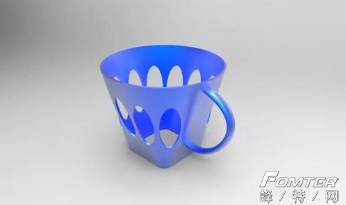
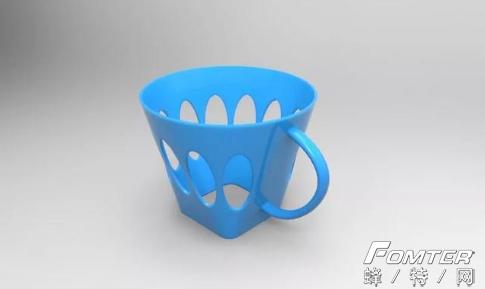
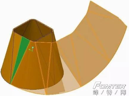
1、按照惯例,首先上传两张渲染效果图,如图所示。
![27dfa827059fec4c038f0f05066496df.png](https://img-blog.csdnimg.cn/img_convert/27dfa827059fec4c038f0f05066496df.png)
![6b07a956117c1304fd96290f99a5ff2b.png](https://img-blog.csdnimg.cn/img_convert/6b07a956117c1304fd96290f99a5ff2b.png)
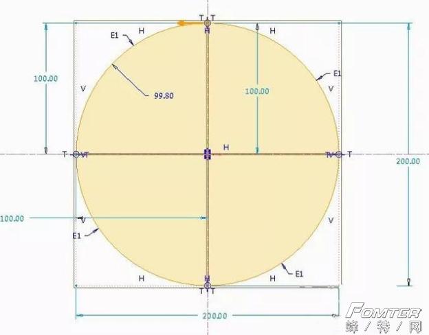
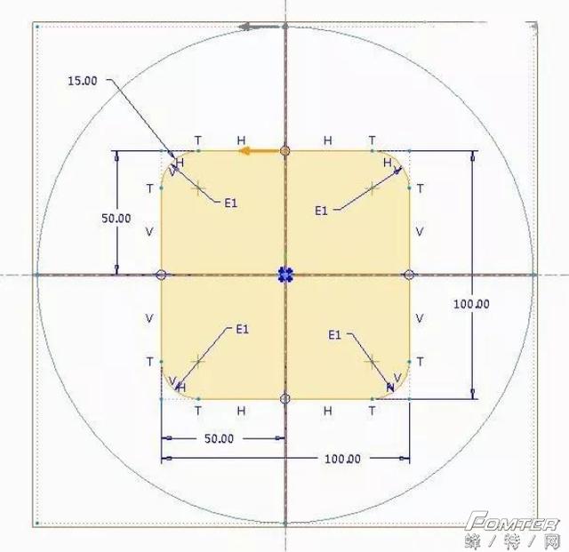
2、打开creo软件,以名称“cha-bei-tuo-jia”新建一个钣金零件,点击“形状--混合”命令,绘制第一个截面,如图所示,注意该截面为矩形倒圆角之后的草图哦。
![67f7ce13c77cdee34891eab387f000ed.png](https://img-blog.csdnimg.cn/img_convert/67f7ce13c77cdee34891eab387f000ed.png)
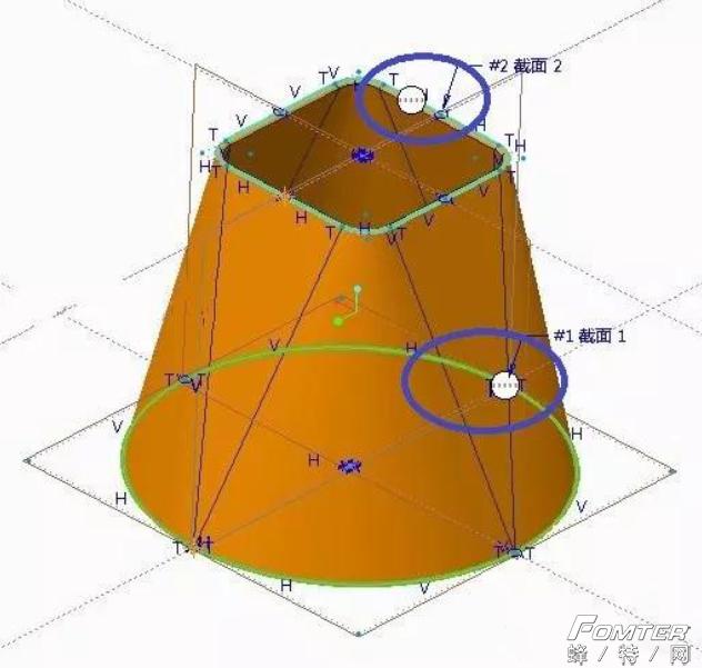
3、完成草图1后,接着以偏移截面1距离160mm绘制如图所示的截面2,同理截面2也为矩形倒圆角之后的草图。
![b1627903bac4d7b6fe80dbc0a0cb0415.png](https://img-blog.csdnimg.cn/img_convert/b1627903bac4d7b6fe80dbc0a0cb0415.png)
![57ac53c6e65c1f63f0ed7f0ca8e26bea.png](https://img-blog.csdnimg.cn/img_convert/57ac53c6e65c1f63f0ed7f0ca8e26bea.png)
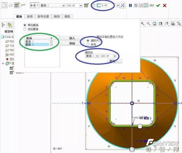
4、完成上述两个截面草绘之后,退出草图,设置钣金壁厚为3mm,完成如图所示的混合建模,注意钣金混合的起点位置。
![7779eb00a29962b7bdfecd0674eeec7e.png](https://img-blog.csdnimg.cn/img_convert/7779eb00a29962b7bdfecd0674eeec7e.png)
5、为方便钣金侧面椭圆孔的创建,需要将该模型进行展平操作,点击“扯裂--草绘扯裂”,绘制如图所示的草图。
![572ce8f1d42dd088809b5b226009ae45.png](https://img-blog.csdnimg.cn/img_convert/572ce8f1d42dd088809b5b226009ae45.png)
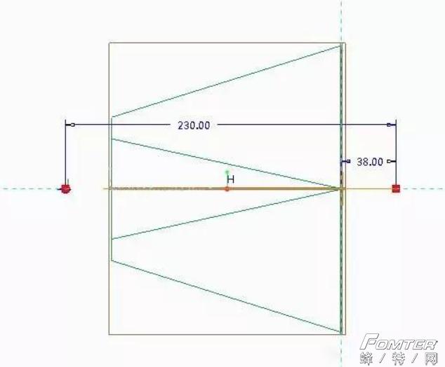
6、完成之后如图所示,为接下来展平作准备。
![e2e80711074501c906b99df105440900.png](https://img-blog.csdnimg.cn/img_convert/e2e80711074501c906b99df105440900.png)
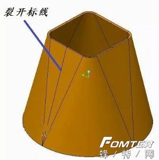
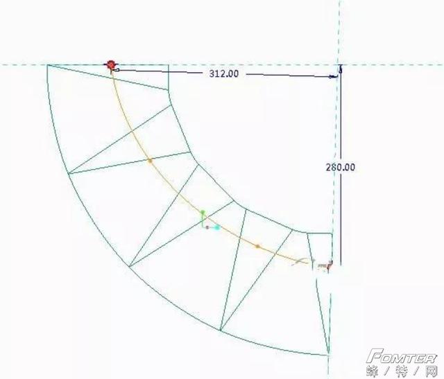
7、点击“展平”,选中步骤6创建的标线,展平该特征,如图所示。
![e40e2bfb27c48cd23a9dbfc7335c801b.png](https://img-blog.csdnimg.cn/img_convert/e40e2bfb27c48cd23a9dbfc7335c801b.png)
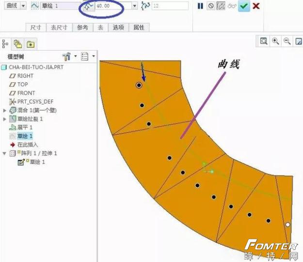
8、选中钣金上表面,点击“草绘”命令,绘制如图所示的样条曲线,为接下来的阵列作准备,尺寸可适当调整哈。
![3cbad2deddca7cfa92898eadd7092adc.png](https://img-blog.csdnimg.cn/img_convert/3cbad2deddca7cfa92898eadd7092adc.png)
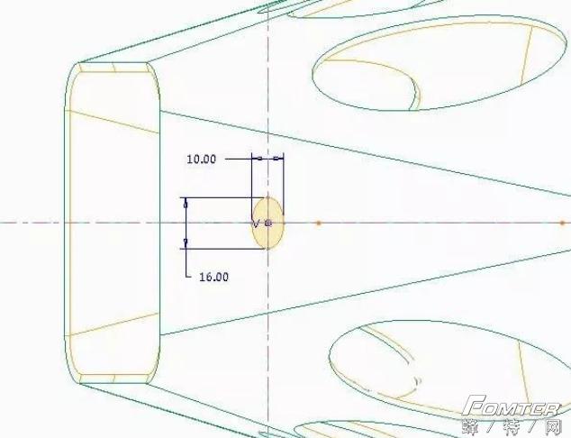
9、点击“拉伸”命令,选中钣金上表面,绘制如图所示的椭圆,注意参考的选择。
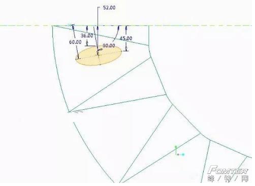
![05fe65b4e4da35ba320ee4f87099e678.png](https://img-blog.csdnimg.cn/img_convert/05fe65b4e4da35ba320ee4f87099e678.png)
10、完成之后,如图所示。
![5a903d7baf15354d4adf8f624e9489f4.png](https://img-blog.csdnimg.cn/img_convert/5a903d7baf15354d4adf8f624e9489f4.png)
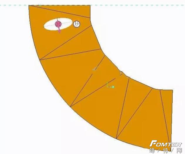
11、选中步骤10创建的拉伸特征,点击“阵列”命令,选择曲线阵列,选中步骤8创建的曲线,并设置阵列间距40mm,阵列个数12个,如图所示。
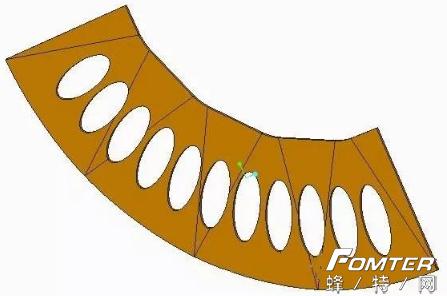
![b59167e94fa5b9aae2b4520938988165.png](https://img-blog.csdnimg.cn/img_convert/b59167e94fa5b9aae2b4520938988165.png)
12、完成阵列如图所示。
![3841e7e549b74188f38f620c5ae5fcb1.png](https://img-blog.csdnimg.cn/img_convert/3841e7e549b74188f38f620c5ae5fcb1.png)
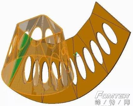
13、点击“折弯回去”命令,完成如图所示的折弯操作。
![68855fbff96bd88147f0f7fa73a6ddb7.png](https://img-blog.csdnimg.cn/img_convert/68855fbff96bd88147f0f7fa73a6ddb7.png)
![b618037c579458eb898cfcb2b5be2305.png](https://img-blog.csdnimg.cn/img_convert/b618037c579458eb898cfcb2b5be2305.png)
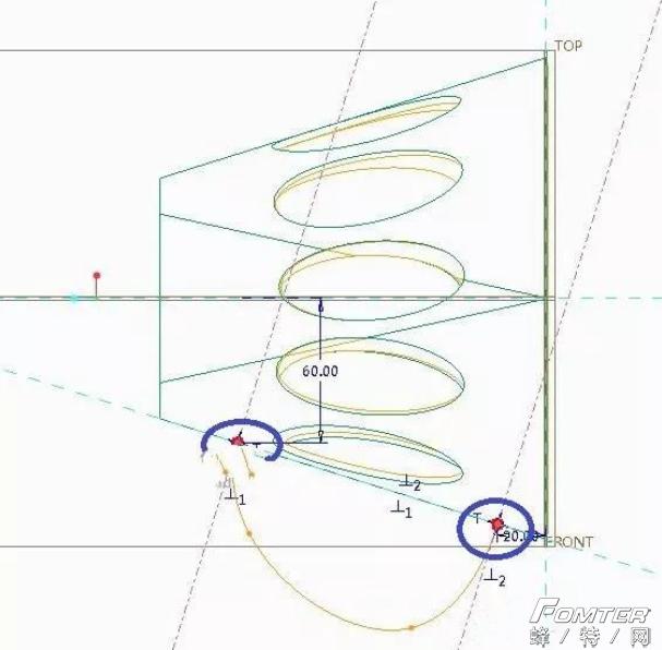
14、选择top平面,点击“草绘”命令,绘制如图所示的草图,注意两个端点与截面的垂直约束,如图所示。
![9773c1432aeff037707335fb49b2069d.png](https://img-blog.csdnimg.cn/img_convert/9773c1432aeff037707335fb49b2069d.png)
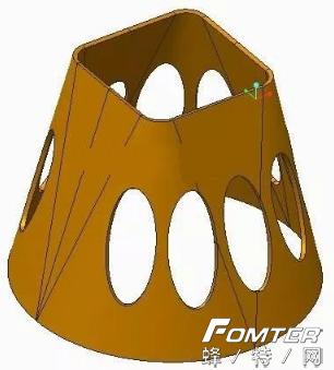
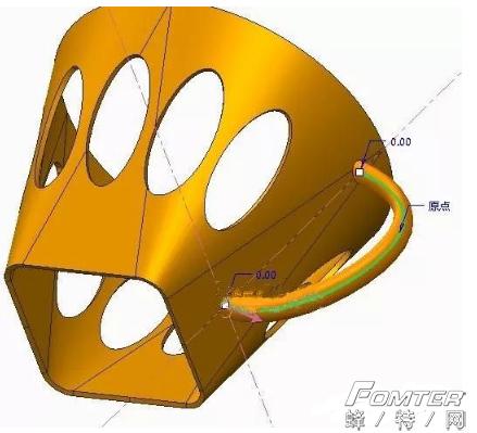
15、点击“形状--扫描”命令,进入草绘,绘制如图所示的椭圆,完成把手的建模,如图所示。
![4dd3be384fc3868429f53d9942ef03ed.png](https://img-blog.csdnimg.cn/img_convert/4dd3be384fc3868429f53d9942ef03ed.png)
![0a5738ecafc4ab058bd0e6af02ae07e3.png](https://img-blog.csdnimg.cn/img_convert/0a5738ecafc4ab058bd0e6af02ae07e3.png)
16、至此,茶杯托架的钣金建模教程完结。