


传感器接线
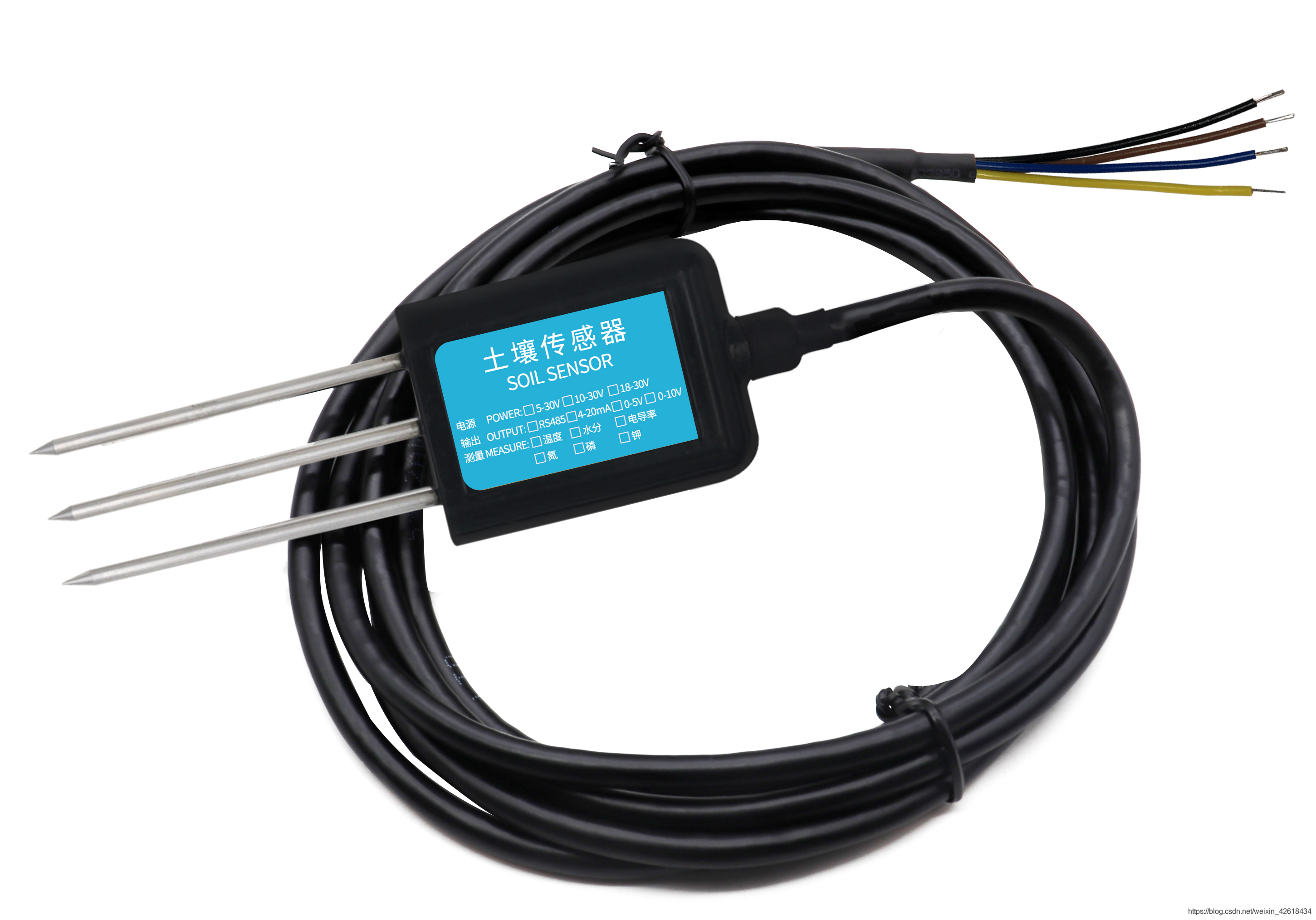
| 颜色 | 说明 | 备注 |
|---|---|---|
| 棕色 | 电源正 | 4.5~30VDC |
| 黑色 | 电源地 | GND |
| 黄色 | 485-A | 485-A |
| 蓝色 | 485-B | 485-B |
将传感器与485转TTL与esp32按照接线表格相连。
根据传感器的说明手册,查看传感器的通信协议,主要查看主机的问询帧结构(说白了就是,你的esp32板子要向传感器发送的数据字符串)和从机的应答帧结构(传感器向板子返回的数据)。这里给出一个示例:
问询帧:
| 地址码 | 功能码 | 起始地址 | 数据长度 | 校验码低字节 | 校验码高字节 |
|---|---|---|---|---|---|
| 0x01 | 0x03 | 0x00 0x00 | 0x00 0x03 | 0x05 | 0xCB |
这个就是需要向485传感器发送的数据,在代码中的展示如下:
// 问询帧
unsigned char item[8] = {0x01, 0x03, 0x00, 0x00, 0x00, 0x03, 0x05, 0xCB};
应答帧
| 地址码 | 功能码 | 返回有效字节数 | 水分值 | 温度值 | 电导率值 | 校验码低字节 | 校验码高字节 |
|---|---|---|---|---|---|---|---|
| 0x01 | 0x03 | 0x06 | 0x02 0x92 | 0xFF 0x9B | 0x03 0xE8 | 0xD8 | 0x0F |
这个数据就是传感器向板子返回的11位的字符串。
数据的意义就如同表格里面表示的,第5、6位表示水分值。
水分计算:
水分:292 H (十六进制)= 658 => 湿度 = 65.8%,即土壤体积含水率为 65.8%。
同样的,温度值的值:
温度:FF9B H(十六进制)= -101 => 温度 = -10.1℃
传感器部分的接线和通信协议已经完成,下面,就是代码部分。
程序实现
先理清需要做哪些工作
- 将esp32通过WIFI联网
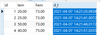
- 建立一个数据库保存温湿度数据(不多赘述)
- 连接数据库
- ESP32获取传感器的数据(向传感器发送数据和接受传感器的数据)
- 将返回的数据进行解析(十六进制转为十进制)
#include <WiFi.h>          // Use this for WiFi instead of Ethernet.h
#include <MySQL_Connection.h>
#include <MySQL_Cursor.h>
#include <stdio.h>

HardwareSerial mySerial1(1); //软串口,用来与传感器进行通信
unsigned char item[8] = {0x01, 0x03, 0x00, 0x00, 0x00, 0x03, 0x05, 0xCB};

IPAddress server_addr(***,***,**,**);  //mysql数据库的ip地址e
char user[] = "*****";              // 数据库的用户名
char password[] = "********";        // 数据库的登陆密码

// Sample query
char INSERT_SQL[] = "INSERT INTO grtrace.arduino_test( tem, hem) VALUES ('%s','%s')";
//grtrace.arduino_test( tem, hem)  建立的数据库名称.表名(值,值)

// WiFi card example
char ssid[] = "*****";         // ESP32连接的无线名称
char pass[] = "**********";     // ESP32连接的无线密码

WiFiClient client;            // Use this for WiFi instead EthernetClient
MySQL_Connection conn(&client);
MySQL_Cursor* cursor;
//下面定义了一个函数,用来与传感器通信和发送温湿度的值到数据库
double *readAndRecordData(){
 static double linshi_d[2];
 String tem="";
 String hem_t ="";
 char tem1[5];
 char hem[4];
 String data = "";
 char buff[128];// 定义存储传感器数据的数组
 String info[11];
 for (int i = 0 ; i < 8; i++) {  // 发送测温命令
   mySerial1.write(item[i]);   // write输出
  }
  delay(100);  // 等待测温数据返回
  data = "";
  while (mySerial1.available()) {//从串口中读取数据
    unsigned char in = (unsigned char)mySerial1.read();  // read读取
    Serial.print(in, HEX);
    Serial.print(',');
    data += in;
    data += ',';
  }
  if (data.length() > 0) { //先输出一下接收到的数据
    Serial.print(data.length());
    Serial.println();
    Serial.println(data);
    int commaPosition = -1;
    // 用字符串数组存储
    for (int i = 0; i < 11; i++) {
    commaPosition = data.indexOf(',');
    if (commaPosition != -1)
    {
      info[i] = data.substring(0, commaPosition);
      data = data.substring(commaPosition + 1, data.length());
    }
    else {
      if (data.length() > 0) {
        info[i] = data.substring(0, commaPosition);
      }
    }
  }
  }
 tem = dtostrf((info[3].toInt() * 256 + info[4].toInt())/10.0,2,1,tem1);
  Serial.print("tem:");
  Serial.println(tem);
 hem_t = dtostrf((info[5].toInt() * 256 + info[6].toInt())/10.0,2,1,hem);
  dtostrf((info[5].toInt() * 256 + info[6].toInt())/10.0,2,1,hem);
  Serial.print("hem:");
  Serial.println(hem);
  sprintf(buff,INSERT_SQL, tem ,hem);
  Serial.println(buff);
  MySQL_Cursor *cur_mem = new MySQL_Cursor(&conn); // 创建一个Mysql实例
 cur_mem->execute(buff);         // 将采集到的温湿度值插入数据库中
 Serial.println("读取传感器数据,并写入数据库");
 delete cur_mem;        // 删除mysql实例为下次采集作准备
 //这里我在项目的应用中,需要把温湿度的数据提取出来,在其他的地方使用,如果实现数据上传功能,下面三行程序可不需要。
 linshi_d[0] =(info[3].toInt() * 256 + info[4].toInt())/10.0 ;
 linshi_d[1] =(info[5].toInt() * 256 + info[6].toInt())/10.0;
 return linshi_d;
}

void setup()
{

  Serial.begin(4800);
  mySerial1.begin(4800,SERIAL_8N1,35,12);
  while (!Serial); // wait for serial port to connect. Needed for Leonardo only

  // Begin WiFi section
  Serial.printf("\nConnecting to %s", ssid);
  WiFi.begin(ssid, pass);
  while (WiFi.status() != WL_CONNECTED) {
    delay(500);
    Serial.print(".");
  }

  // print out info about the connection:
  Serial.println("\nConnected to network");
  Serial.print("My IP address is: ");
  Serial.println(WiFi.localIP());

  Serial.print("Connecting to SQL...  ");
  if (conn.connect(server_addr, 3366, user, password))
    Serial.println("OK.");
  else
    Serial.println("FAILED.");

  // create MySQL cursor object
  cursor = new MySQL_Cursor(&conn);
}

void loop()
{
  if (conn.connected()){

      double *linshi_tem;
      double *linshi_hem;
      double *linshi_temp;
     //调用readAndRecordData()即可
      linshi_temp = readAndRecordData();
      *linshi_tem = *(readAndRecordData()+1);
      Serial.println(*linshi_temp);
      Serial.println(*linshi_tem);
      delay(5000);
  }
}
欢迎各位小伙伴评论收藏!!!
参考文章
(https://blog.csdn.net/xiaoshihd/article/details/109398264)


 1401
1401


 被折叠的 条评论
为什么被折叠?
被折叠的 条评论
为什么被折叠?
 到【灌水乐园】发言


