


串口是单片机最重要的外设之一,在很多项目开发中都有应用,Lora模块的外部通讯方式就是串口。
本节简单的和大家解析一下串口通讯及驱动代码的编程。
STM8L101F3单片机支持一路串口通讯。我们先看一下Lora模块的硬件接口,如下图所示:

串口的硬件接口是PC2 和PC3两个脚位。
下面开始讲解软件部分,这块我们无际单片机编程也有这个项目全部视频教程,下面是文字版。
软件驱动
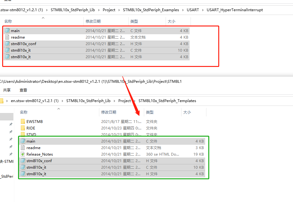
- STM8打开标准库文件夹,打开串口USART例程:

2.如上图所示,是标准库中串口通讯的的例程,并选择第一个例程。

3.我们按照之前的方式,把USART_HyperTerminalInterrupt文件复制到\Project\STM8L10x_StdPeriph_Templates 中,如下图。
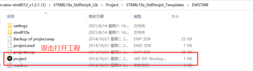
4.进入\Project\STM8L10x_StdPeriph_Templates\EWSTM8,打开工程

5.我们简单的看一下串口的初始化代码
static void USART_Config(void){/*High speed internal clock prescaler: 1*/CLK_MasterPrescalerConfig(CLK_MasterPrescaler_HSIDiv1);/*Set the USART RX and USART TX at high level*/GPIO_ExternalPullUpConfig(GPIOC,GPIO_Pin_3|GPIO_Pin_4, ENABLE);/* Enable USART clock */CLK_PeripheralClockConfig(CLK_Peripheral_USART, ENABLE);USART_DeInit();/* USART configuration ------------------------------------------------------*//* USART configured as follow:- BaudRate = 9600 baud- Word Length = 8 Bits- One Stop Bit- Odd parity- Receive and transmit enabled*/USART_Init((uint32_t)9600, USART_WordLength_8D, USART_StopBits_1,USART_Parity_Odd, (USART_Mode_TypeDef)(USART_Mode_Rx | USART_Mode_Tx));/* Enable the USART Transmit interrupt: this interrupt is generated when theUSART transmit data register is empty */USART_ITConfig(USART_IT_TXE, ENABLE);/* Enable the USART Receive interrupt: this interrupt is generated when theUSART receive data register is not empty */USART_ITConfig(USART_IT_RXNE, ENABLE);/* Enable general interrupts */enableInterrupts();}
①第一条代码: CLK_MasterPrescalerConfig(CLK_MasterPrescaler_HSIDiv1);
单片机工作系统时钟配置函数,内部系统时钟16M,
CLK_MasterPrescaler_HSIDiv1表示1分频 系统工作时钟16M
其他可配置参数如下图:
typedef enum {CLK_MasterPrescaler_HSIDiv1 = (uint8_t)0x00, /*!< High speed internal clock prescaler: 1 */CLK_MasterPrescaler_HSIDiv2 = (uint8_t)0x01, /*!< High speed internal clock prescaler: 2 */CLK_MasterPrescaler_HSIDiv4 = (uint8_t)0x02, /*!< High speed internal clock prescaler: 4 */CLK_MasterPrescaler_HSIDiv8 = (uint8_t)0x03 /*!< High speed internal clock prescaler: 8 */} CLK_MasterPrescaler_TypeDef;
②第二条代码: GPIO_ExternalPullUpConfig(GPIOC,GPIO_Pin_3|GPIO_Pin_4, ENABLE);
串口GPIO口配置。例程的端口是PC2 PC3.
STM8L101F3的串口端口是PC2 和PC3,这个地方需要修改
③第三条代码:CLK_PeripheralClockConfig(CLK_Peripheral_USART, ENABLE);
打开串口时钟函数,初始化串口的时候,首先要打开串口时钟。
④第四条代码:USART_DeInit();
串口复位函数,复位串口相关的寄存器。
⑤第五条代码:USART_Init((uint32_t)9600, USART_WordLength_8D, USART_StopBits_1,
USART_Parity_Odd, (USART_Mode_TypeDef)(USART_Mode_Rx | USART_Mode_Tx));
串口初始化函数。我们打开串口库函数“stm8l10x_usart.c”,查看本函数的原型。
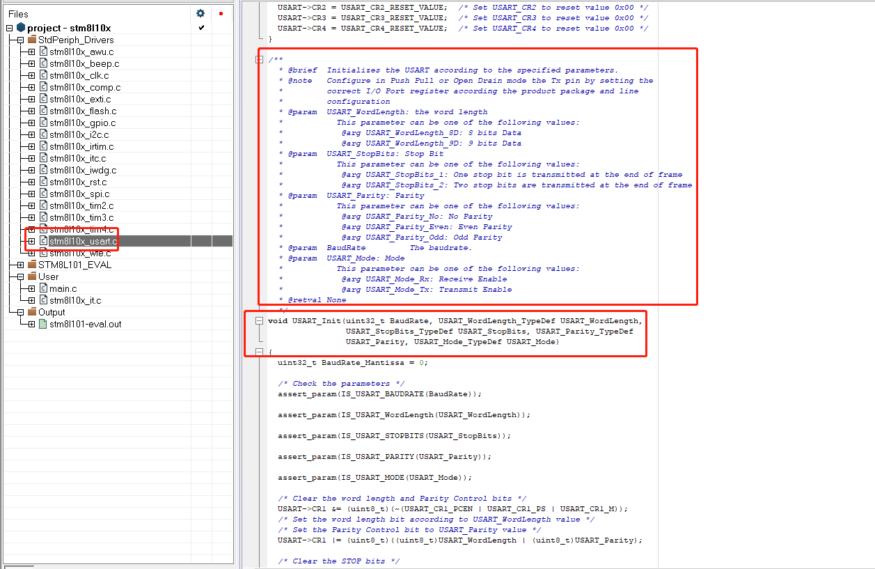
如上图所示,这个函数是串口的初始化函数,我们研究一下这个函数的相关参数。
参数1:uint32_t BaudRate, 配置串口通讯的波特率,可配置为9600,115200等
参数2:USART_WordLength_TypeDef USART_WordLength 配置通讯数据的位数。
可选参数项:
USART_WordLength_8D: 8 bits Data
USART_WordLength_9D: 9 bits Data
参数3: USART_StopBits_TypeDef USART_StopBits, 串口通讯的停止位
可选参数项:
USART_StopBits_1 :One stop bit is transmitted at the end of frame
USART_StopBits_2 :Two stop bits are transmitted at the end of frame
参数4: USART_Parity_TypeDef USART_Parity 奇偶校验位 配置
可配置的参数:
typedef enum
{
USART_Parity_No = (uint8_t)0x00, /*!< No Parity*/
USART_Parity_Even = (uint8_t)0x04, /*!< Even Parity*/
USART_Parity_Odd = (uint8_t)0x06 /*!< Odd Parity*/
} USART_Parity_TypeDef;
参数5:USART_Mode_TypeDef USART_Mode 配置串口的通讯使能。
typedef enum
{
USART_Mode_Rx = (uint8_t)0x04, /*!< 0x04 Receive Enable */
USART_Mode_Tx = (uint8_t)0x08 /*!< 0x08 Transmit Enable */
} USART_Mode_TypeDef;
⑥第六条代码:USART_ITConfig(USART_IT_TXE, ENABLE);
串口通讯数据发送中断使能函数: 用来配置是否打开串口通讯数据发送中断功能
⑦第七条代码:USART_ITConfig(USART_IT_RXNE, ENABLE);
串口通讯数据接收中断使能函数: 用来配置是否打开串口通讯数据接收中断功能
⑧第八条代码: enableInterrupts();
打开总中断功能。
6.我们简单的看一下串口的初始化代码
INTERRUPT_HANDLER(USART_TX_IRQHandler, 27) 串口发送中断函数
INTERRUPT_HANDLER(USART_RX_IRQHandler, 28) 串口接收中断函数
定时器实验测试:
1.我们先打开Lora模块的原理图如下:

2.官网的例程的初始化程序我们刚才已经已经分析过来,但我们需要对官网的例程简单的修改一下。如下:
static void USART_Config(void){CLK_MasterPrescalerConfig(CLK_MasterPrescaler_HSIDiv1);GPIO_ExternalPullUpConfig(GPIOC,GPIO_Pin_3|GPIO_Pin_2, ENABLE);CLK_PeripheralClockConfig(CLK_Peripheral_USART, ENABLE);USART_DeInit();/* USART configuration ------------------------------------------------------*//* USART configured as follow:- BaudRate = 9600 baud- Word Length = 8 Bits- One Stop Bit- Odd parity- Receive and transmit enabled*/USART_Init((uint32_t)9600, USART_WordLength_8D, USART_StopBits_1,USART_Parity_No, (USART_Mode_TypeDef)(USART_Mode_Rx | USART_Mode_Tx));USART_ITConfig(USART_IT_TXE, ENABLE);USART_ITConfig(USART_IT_RXNE, ENABLE);enableInterrupts();}
如上图,我修改了两个地方:
①修改了初始化的端口, 因STM8L101F3的这款单片机的串口是PC2和PC3. 所以讲PC4修改成PC3;
②通讯验证的方式,之前是奇校验,修改成无校验。
我们工作中最常用的通讯方式就是无校验。所以我们以无校验来做实验测试。
3.我们在看一下无线发射和接收的中断服务函数:
①串口接收中断服务函数:
串口接收中断服务函数原代码:
#define RxBufferSize 0x20uint8_t RxBuffer[RxBufferSize];uint16_t RxCounter = 0;uint8_t NbrOfDataToRead = RxBufferSize;INTERRUPT_HANDLER(USART_RX_IRQHandler, 28){STM_EVAL_LEDInit(LED3);/* Read one byte from the receive data register */RxBuffer[RxCounter++] = (uint8_t) (USART_ReceiveData8() & 0x7F);if (RxCounter == NbrOfDataToRead){STM_EVAL_LEDToggle(LED3);/* Disable the USART Receive interrupt */USART_ITConfig(USART_IT_RXNE, DISABLE);}}
因原代码是奇校验接收函数,我们简单的修改一下,修改后代码如下:
INTERRUPT_HANDLER(USART_RX_IRQHandler, 28){uint8_t temp;temp = (uint8_t) USART_ReceiveData8();// & 0x7F);USART_SendData8(temp);}
实现的功能,就是将无线接收的数据,通过串口返回。
USART_SendData8(temp); 串口无线发送函数,原型如下:/*** @brief Transmits 8 bit data through the USART peripheral.* @param Data The data to transmit.* @retval None*/void USART_SendData8(uint8_t Data){/* Transmit Data */USART->DR = Data;}
②串口发送中断服务函数:
串口数据发送终端服务原代码:
#define TxBufferSize (countof(TxBuffer) - 1)uint8_t TxBuffer[] = "\n\rHyperTerminal Interrupt: USART-Hyperterminal communication using Interrupt\n\r";uint8_t NbrOfDataToTransfer = TxBufferSize;uint8_t TxCounter = 0;INTERRUPT_HANDLER(USART_TX_IRQHandler, 27){STM_EVAL_LEDInit(LED2);/* Write one byte to the transmit data register */USART_SendData8(TxBuffer[TxCounter++]);if (TxCounter == NbrOfDataToTransfer){STM_EVAL_LEDToggle(LED2);/* Disable the USART Transmit interrupt */USART_ITConfig(USART_IT_TXE, DISABLE);}}
主要实现的功能:
1.设备上电后,串口会自动发送数据”\n\rHyperTerminal Interrupt: USART-Hyperterminal communication using Interrupt\n\r”;
2.数据发送完成之后,关闭串口发送中断功能。
USART_ITConfig(USART_IT_TXE, DISABLE); 函数表示关闭串口发送中断功能。
以上的代码我们制作一个简单的修改。修改uint8_t TxBuffer[]的值,修改如下:
uint8_t TxBuffer[] = “\n\rLora,STM8 Usart Tx Interrupt Test \n\r”;
③编译并下载代码到Lora模块,并Lora模块的串口连接到电脑。连接如下图所示:

④在电脑端打开串口助手,并配置串口参数,打开串口,测试数据如下:
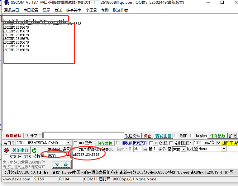
串口实验测试完成。


 6万+
6万+


 被折叠的 条评论
为什么被折叠?
被折叠的 条评论
为什么被折叠?
 到【灌水乐园】发言


