


【路径跟踪】后轮误差反馈跟踪算法个人总结|python|c++|Webots
参考资料
1. rear_wheel_feedback_control路径跟踪算法
最近在做项目需要仿真一个前轮转向、驱动的自走剪叉式升降平台底盘,其中需要对路径跟踪,正好借此机会将之前了解过的路径跟踪类的知识应用一下。后轮误差反馈跟踪是基于底盘后轴中心点相对于参考路径横向误差和底盘航向角误差的控制方法。
1.1 算法思想
-
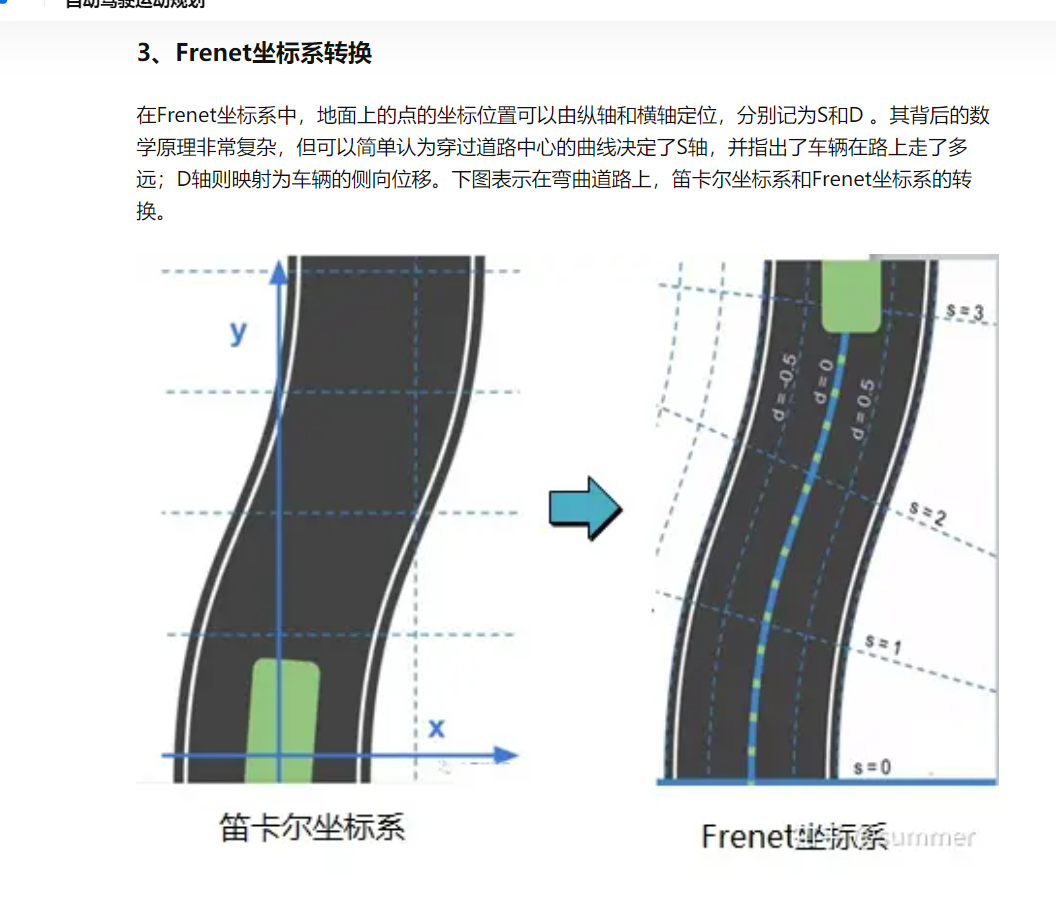
为了更好的描述车辆(车辆底盘模型参考)与道路的坐标关系,一般不用世界坐标系描述,而是用Frenet坐标系来描述车辆在路上与道路中心的相对横向误差与角度误差。Frenet坐标系的建立我参考的这篇博客


-
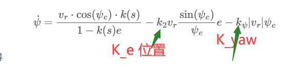
在Frenet坐标系中,车辆具有以上的三个状态微分方程,对车辆系统进行稳定性判定,根据李雅普诺夫第二判据,对状态方程进行稳定性判定,并得到可以使得车辆系统趋于稳定点(参考路径点)的控制律。李雅普诺夫函数建立与判定参考的李雅普诺夫(第二方法)稳定性分析+例题和这篇博客
1.2 公式
这里不在阐述,参考的网上的 【自动驾驶】后轮位置反馈实现轨迹跟踪 | python实现 | c++实现
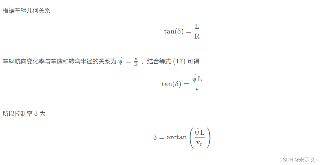
重点圈出:其中我们需要知道我们需要怎么计算前轮转角即可。
其中公式计算的是车辆转动角速度,然后通过车辆转动角速度与前轮转角的关系公式可以反解算出车辆前轮的转动角度。
1.3 算法流程
- 输入:当前车辆位置(后轮中心的位置)XY;航向角 θ \theta θyaw;速度v(注意这里用的是后轮的速度);参考路径点处的航向角,即切线角ref_yaw;参考路径点处的斜率ref_k
- 根据当前机器人速度v、和目标速度target_v,PID控制器单纯P控制器计算加速度
- 根据当前坐标寻找参考路径上的最近的参考路径点坐标ref_pos及其索引ref_index
- 根据Frenet坐标系中横向误差的计算方式(叉积)计算error,同时计算
yaw_error = ref_yaw - yaw控制律计算输出角速度,再计算前轮转角delta - 然后更新机器人状态
2. python代码
2.1 车辆模型
四轮阿克曼转向底盘一般简化为双轮单车模型

2.2 参考路径生成 | 斜率计算
部分代码示意:
class RefPath:
    def __init__(self):
        # 画参考路径
        map_R = 5.3 / 2
        map_L = 4

        self.ref_path = np.zeros((50, 2))
        self.ref_path[:, 0] = map_R * 6
        self.ref_path[:, 1] = np.linspace(0, 2 * map_L - 0.5, 50)

        theta = np.linspace(0, 1 * np.pi, 40).reshape(-1, 1)
        x = map_R * 5 + map_R * np.cos(theta)
        y = map_L * 2 + map_R * np.sin(theta)
        self.ref_path = np.vstack((self.ref_path, np.hstack((x, y))))

        self.dx = np.diff(self.ref_path[:, 0])
        self.dy = np.diff(self.ref_path[:, 1])
        self.dx = np.append(self.dx, self.dx[-1])
        self.dy = np.append(self.dy, self.dy[-1])
        self.ddx = np.diff(self.dx)
        self.ddy = np.diff(self.dy)
        self.ddx = np.append(self.ddx, self.ddx[-1])
        self.ddy = np.append(self.ddy, self.ddy[-1])

        self.ref_yaw = np.arctan2(self.dy, self.dx)  # yaw
        self.ref_yaw = np.mod((2 * np.pi + self.ref_yaw), 2 * np.pi)

        # 计算曲率:设曲线r(t) =(x(t),y(t)),则曲率k=(x'y" - x"y')/((x')^2 + (y')^2)^(3/2).
        self.ref_k = (self.ddy * self.dx - self.ddx * self.dy) / (
            (self.dx**2 + self.dy**2) ** (3 / 2)
        )  # 曲率k计算

2.3 初始参数设置
# initialization相关参数定义
K_theta = 1 # 航向角误差系数
K_e = 0.5 # 横向误差系数
dt = 0.05 # 控制时间间隔
L = 2.24 # 车前后轴距
x_0 = 17 #起始坐标
y_0 = 0
yaw_0 = np.pi / 2 * 2 # 起始航向角,给了一个起始误差
v_0 = 0
target_v = 1 # m/s 目标速度
2.4 速度跟随
这里只需简单计算,用一个P控制器即可
def PIDcontrol(target_v, current_v, Kp):
	# 计算加速度的函数
    return Kp * (target_v - current_v)
2.5 搜索最近参考路径点
遍历搜索距离当前车辆坐标点最近的路径点,输出最后的路径点索引值target_index
    def calc_track_error(self, x, y):
        """计算跟踪误差"""
        d_x = [x - self.ref_path[i, 0] for i in range(len(self.ref_path))]
        d_y = [y - self.ref_path[i, 1] for i in range(len(self.ref_path))]
        dist = [np.sqrt(d_x[i] ** 2 + d_y[i] ** 2) for i in range(len(d_x))]
        idx = np.argmin(dist) # 最近参考点索引值

        yaw = self.ref_yaw[idx]
        k = self.ref_k[idx] # 斜率
        error = np.cos(yaw) * d_y[idx] - np.sin(yaw) * d_x[idx] # 横向误差计算

        return error, k, yaw, idx
2.6 计算后轮误差反馈跟踪算法 | 前轮转角计算
def rear_wheel_feedback_control(state, e, k, ref_yaw):
    yaw, v = state.yaw, state.v
    yaw_e = yaw - ref_yaw

    if yaw_e == 0.0: # 注意除数为零异常
        omega = (
            v * k * np.cos(yaw_e) / (1.0 - k * e)
            - K_e * v * e
            - K_theta * abs(v) * yaw_e
        )
    else:
        # 计算 角速度
        omega = (
            v * k * np.cos(yaw_e) / (1.0 - k * e)
            - K_e * v * np.sin(yaw_e) * e / yaw_e
            - K_theta * abs(v) * yaw_e
        )

    if v == 0.0:# 注意除数为零异常
        return 0.0
    delta = np.arctan2(L * omega, v)
    return delta
2.7 更新车辆状态
    def update_state(self, a, delta_f):
        self.x = self.x + self.v * np.cos(self.yaw) * self.dt
        self.y = self.y + self.v * np.sin(self.yaw) * self.dt
        self.yaw = self.yaw + self.v / self.L * np.tan(delta_f) * self.dt
        self.v = a * self.dt + self.v
2.8 主函数
def main():
    path = RefPath()
    goal = path.ref_path[-1, :]
    robot = KinematicModel(x_0, y_0, yaw_0, v_0, L, dt)
    x_ = []
    y_ = []
    k_list = []

    time = 0
    fig = plt.figure(1)
    i = 0
    while 100 > time:
        i += 1
        ai = PIDcontrol(target_v, robot.v, 0.8)
        e, k, ref_yaw, idx = path.calc_track_error(robot.x, robot.y)

        delta = rear_wheel_feedback_control(robot, e, k, ref_yaw)

        x_.append(robot.x)
        y_.append(robot.y)

        robot.update_state(ai, delta)
        time += dt
        plt_flag = False
        if plt_flag:
            plt.cla()
            plt.plot(
                path.ref_path[:, 0],
                path.ref_path[:, 1],
                "-.b",
                linewidth=1.0,
                label="course",
            )
            plt.plot(x_, y_, "-r", label="trajectory")
            plt.plot(
                path.ref_path[idx, 0],
                path.ref_path[idx, 1],
                "go",
                label="target",
            )
            plt.grid(True)
            plt.pause(0.001)

        if abs(robot.x - goal[0]) < 0.2 and abs(robot.y - goal[1]) < 0.2:
            print("reach goal")
            break
2.9 运行效果
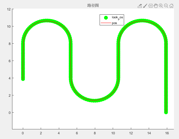
蓝色点划线为参考路径,红色为实际路径,从右下角开始,初始点是给了坐标偏差和角度偏差的,所以机器人会先进行一波小调整才回到直线上。总体跟踪效果还可以。但是注意我所跟踪的路径在直线段与圆相接的地方是曲率突变的,所以会导致在相接的地方前轮转角突变的其实。

2.10 完整python代码
需要常见的一些py库。
"""
LastEditors  : 未定义
Date         : 2023-09-07 10:27:07
LastEditTime : 2023-09-08 10:25:31
FilePath     : \python\copy_rear_wheel_control.py
"""
import numpy as np
import matplotlib.pyplot as plt
import math
import csv
import pandas as pd
from celluloid import Camera  # 保存动图时用,pip install celluloid

# initialization相关参数定义
K_theta = 1  # 航向角误差系数
K_e = 0.5  # 横向误差系数
dt = 0.1  # 控制时间间隔
L = 2.24  # 车前后轴距
x_0 = 17  # 起始坐标
y_0 = 0
yaw_0 = np.pi / 2 * 2  # 起始航向角,给了一个起始误差
v_0 = 0
target_v = 1  # m/s 目标速度


class KinematicModel:
    def __init__(self, x, y, yaw, v, L, dt):
        self.x = x
        self.y = y
        self.yaw = yaw
        self.v = v
        self.L = L
        self.dt = dt

    def update_state(self, a, delta_f):
        self.x = self.x + self.v * np.cos(self.yaw) * self.dt
        self.y = self.y + self.v * np.sin(self.yaw) * self.dt
        self.yaw = self.yaw + self.v / self.L * np.tan(delta_f) * self.dt
        self.v = a * self.dt + self.v

    def get_state(self):
        return self.x, self.y, self.yaw, self.v


class RefPath:
    def __init__(self):
        # 画参考路径
        map_R = 5.3 / 2
        map_L = 4

        self.ref_path = np.zeros((50, 2))
        self.ref_path[:, 0] = map_R * 6
        self.ref_path[:, 1] = np.linspace(0, 2 * map_L - 0.5, 50)

        theta = np.linspace(0, 1 * np.pi, 40).reshape(-1, 1)
        x = map_R * 5 + map_R * np.cos(theta)
        y = map_L * 2 + map_R * np.sin(theta)
        self.ref_path = np.vstack((self.ref_path, np.hstack((x, y))))

        x = np.linspace(map_R * 4, map_R * 4, 30).reshape(-1, 1)
        y = np.linspace(map_L * 2 - 0.5, map_L + 0.5, 30).reshape(-1, 1)
        self.ref_path = np.vstack((self.ref_path, np.hstack((x, y))))

        theta = np.linspace(0, -1 * np.pi, 40).reshape(-1, 1)
        x = map_R * 3 + map_R * np.cos(theta)
        y = map_L + map_R * np.sin(theta)
        self.ref_path = np.vstack((self.ref_path, np.hstack((x, y))))

        x = np.linspace(map_R * 2, map_R * 2, 30).reshape(-1, 1)
        y = np.linspace(map_L + 0.5, map_L * 2 - 0.5, 30).reshape(-1, 1)
        self.ref_path = np.vstack((self.ref_path, np.hstack((x, y))))

        theta = np.linspace(0, 1 * np.pi, 40).reshape(-1, 1)
        x = map_R + map_R * np.cos(theta)
        y = map_L * 2 + map_R * np.sin(theta)
        self.ref_path = np.vstack((self.ref_path, np.hstack((x, y))))

        x = np.linspace(map_R * 0, map_R * 0, 30).reshape(-1, 1)
        y = np.linspace(map_L * 2 - 0.5, 3, 30).reshape(-1, 1)
        self.ref_path = np.vstack((self.ref_path, np.hstack((x, y))))

        self.dx = np.diff(self.ref_path[:, 0])
        self.dy = np.diff(self.ref_path[:, 1])
        self.dx = np.append(self.dx, self.dx[-1])
        self.dy = np.append(self.dy, self.dy[-1])
        self.ddx = np.diff(self.dx)
        self.ddy = np.diff(self.dy)
        self.ddx = np.append(self.ddx, self.ddx[-1])
        self.ddy = np.append(self.ddy, self.ddy[-1])

        self.ref_yaw = np.arctan2(self.dy, self.dx)  # yaw
        self.ref_yaw = np.mod((2 * np.pi + self.ref_yaw), 2 * np.pi)

        # 计算曲率:设曲线r(t) =(x(t),y(t)),则曲率k=(x'y" - x"y')/((x')^2 + (y')^2)^(3/2).
        self.ref_k = (self.ddy * self.dx - self.ddx * self.dy) / (
            (self.dx**2 + self.dy**2) ** (3 / 2)
        )  # 曲率k计算

    def calc_track_error(self, x, y):
        """计算跟踪误差"""
        d_x = [x - self.ref_path[i, 0] for i in range(len(self.ref_path))]
        d_y = [y - self.ref_path[i, 1] for i in range(len(self.ref_path))]
        dist = [np.sqrt(d_x[i] ** 2 + d_y[i] ** 2) for i in range(len(d_x))]
        idx = np.argmin(dist)  # 最近参考点索引值

        yaw = self.ref_yaw[idx]
        k = self.ref_k[idx]  # 斜率
        error = np.cos(yaw) * d_y[idx] - np.sin(yaw) * d_x[idx]  # 横向误差计算

        return error, k, yaw, idx


def PIDcontrol(target_v, current_v, Kp):
    # 计算加速度的函数
    return Kp * (target_v - current_v)


def rear_wheel_feedback_control(state, e, k, ref_yaw):
    yaw, v = state.yaw, state.v
    yaw_e = yaw - ref_yaw

    if yaw_e == 0.0:  # 注意除数为零异常
        omega = (
            v * k * np.cos(yaw_e) / (1.0 - k * e)
            - K_e * v * e
            - K_theta * abs(v) * yaw_e
        )
    else:
        # 计算 角速度
        omega = (
            v * k * np.cos(yaw_e) / (1.0 - k * e)
            - K_e * v * np.sin(yaw_e) * e / yaw_e
            - K_theta * abs(v) * yaw_e
        )

    if v == 0.0:
        return 0.0

    delta = np.arctan2(L * omega, v)
    return delta


def main():
    path = RefPath()
    goal = path.ref_path[-1, :]
    robot = KinematicModel(x_0, y_0, yaw_0, v_0, L, dt)
    x_ = []
    y_ = []
    k_list = []
    fig = plt.figure(1)
    # 保存动图用
    # camera = Camera(fig)

    time = 0
    i = 0
    while 100 > time:
        i += 1
        ai = PIDcontrol(target_v, robot.v, 0.8)
        e, k, ref_yaw, idx = path.calc_track_error(robot.x, robot.y)

        delta = rear_wheel_feedback_control(robot, e, k, ref_yaw)

        x_.append(robot.x)
        y_.append(robot.y)

        robot.update_state(ai, delta)
        time += dt
        plt_flag = True
        if plt_flag:
            plt.cla()
            plt.plot(
                path.ref_path[:, 0],
                path.ref_path[:, 1],
                "-.b",
                linewidth=1.0,
                label="course",
            )
            plt.plot(x_, y_, "-r", label="trajectory")
            plt.plot(
                path.ref_path[idx, 0],
                path.ref_path[idx, 1],
                "go",
                label="target",
            )
            plt.grid(True)
            plt.pause(0.001)

        # camera.snap()
        if abs(robot.x - goal[0]) < 0.2 and abs(robot.y - goal[1]) < 0.2:
            print("reach goal")
            break

    # animation = camera.animate()
    # animation.save("trajectory.gif")

    plt.close()
    plt.subplots(1)
    plt.plot(x_, y_, "-r", label="trajectory")
    plt.grid(True)
    plt.plot(
        path.ref_path[:, 0],
        path.ref_path[:, 1],
        "-.b",
        linewidth=1.0,
        label="course",
    )
    plt.show()

    # column = ["data"]
    # k_list = np.round(path.ref_k, 3)
    # test = pd.DataFrame(columns=column, data=k_list)
    # np.round
    # test.to_csv("k_data.csv", header=False, index=False)


if __name__ == "__main__":
    main()
3 移植到Webots仿真 | c++
3.1 主要部分改成C++代码
从matlab移植到webots里仿真,以下是算法部分c++代码供参考。
#include <vector>
#include <cmath>
#include <algorithm>
#include <iostream>

vector<vector<float>> ref_pos = {{15.9000000000000, 0}, {15.9000000000000, 0.163265306122449};
vector<float> ref_yaw = {1.57079632679490, 1.57079632679490};
vector<float> ref_k = {0.0, 0.0}
float target_speed = 1; // m / s
float Kp = 0.8;

float K_e = 1.5;   //
float K_theta = 1; // %

float L = 2.24; // % 车辆轴距,单位:m
float path_latError;
float path_yaw;
vector<float> look_pos;
float out_ld;

float PID_vel_control(float target_v, float current_v, float kp)
{
    return kp * (target_v - current_v);
}

float delta_control(int idx, vector<float> pos, float yaw, float v, vector<vector<float>> ref_pos, vector<float> ref_yaw)
{
    int sizeOfRefPos = ref_pos.size();
    vector<float> Point_temp;

    if (idx < sizeOfRefPos)
        Point_temp = ref_pos[idx];
    else
    {
        Point_temp = ref_pos[sizeOfRefPos];
        idx = sizeOfRefPos;
    }

    float error = (cos(ref_yaw[idx]) * (pos[1] - Point_temp[1]) - sin(ref_yaw[idx]) * (pos[0] - Point_temp[0]));
    float yaw_e = yaw - ref_yaw[idx];

    path_latError = error;
    path_yaw = ref_yaw[idx];

    // % 前轮转角
    float k = ref_k[idx];
    float e = error;
    float omega;
    if (yaw_e == 0.0)
        omega = (v * k * cos(yaw_e) / (1.0 - k * e) - K_e * v * e - K_theta * abs(v) * yaw_e);
    else
        // # 计算 角速度
        omega = (v * k * cos(yaw_e) / (1.0 - k * e) - K_e * v * sin(yaw_e) * e / yaw_e - K_theta * abs(v) * yaw_e);

    if (v == 0.0)
        return 0.0;

    float delta = atan2(L * omega, v);

    printf("error: %4.2f, delta: %4.2f\n", error, Rad2Deg(delta));
    return delta;
}

int findLookaheadPoint(vector<float> pos, float v, vector<vector<float>> RefPos)
{
    //    % 找到距离当前位置最近的一个参考轨迹点的序号
    int sizeOfRefPos = RefPos.size();
    vector<float> dist;
    for (int i = 0; i < sizeOfRefPos; i++)
        dist.push_back(hypot(RefPos[i][0] - pos[0], RefPos[i][1] - pos[1]));

    int idx = min_element(dist.begin(), dist.end()) - dist.begin();
    return idx;
}

float run(float time, float &v, float yaw, vector<float> pos, int dt)
{
    float ai = PID_vel_control(target_speed, v, Kp);
    int target_index = findLookaheadPoint(pos, v, ref_pos); // % 输出距离车辆当前最近的点的位置
    float delta = delta_control(target_index, pos, yaw, v, ref_pos, ref_yaw);

    vector<vector<float>> path_look, path_pos;
    path_look.push_back(ref_pos[target_index]);
    path_pos.push_back(pos);

    v = v + ai * dt * 0.001;
    cout << "v:" << v << " ai: " << ai << endl;
    delta = Limit(delta, Deg2Rad(77.5), Deg2Rad(-77.5));
    look_pos = ref_pos[target_index];
    return delta;
}
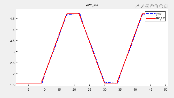
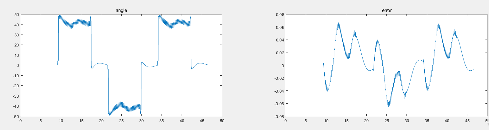
3.2 仿真结果
在webots仿真环境中实验后轮误差反馈控制路径跟踪,可以看见直线与圆相切处,曲率二阶不连续,导致前轮转角突变,如果速度快,就会翻车其实。

跟踪效果:良好的图:
数据分析:红色参考航向角,蓝色实际航向角,存在小误差
左侧是前轮转角,可以看到突变(因为曲率二阶不连续)。右边是横向误差,存在小误差,小振荡。效果还行。
4. 总结
后轮误差反馈跟踪是基于Frenet坐标系运动方程所建立的运动模型而计算出前轮转角控制律的,其控制律与航向角误差和横向误差有关,可以对底盘的航向角和横向误差进行反馈控制。
对该算法该博客有一个总结可以参考:

以上只是个人总结,如个人理解有误,见谅。


 被折叠的 条评论
为什么被折叠?
被折叠的 条评论
为什么被折叠?
 到【灌水乐园】发言


