


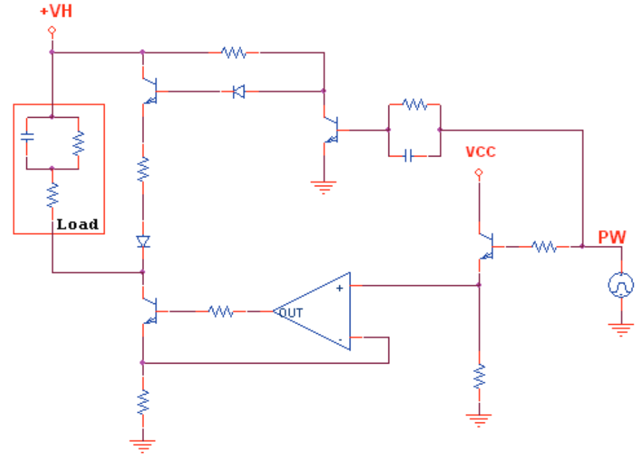
电路原理图
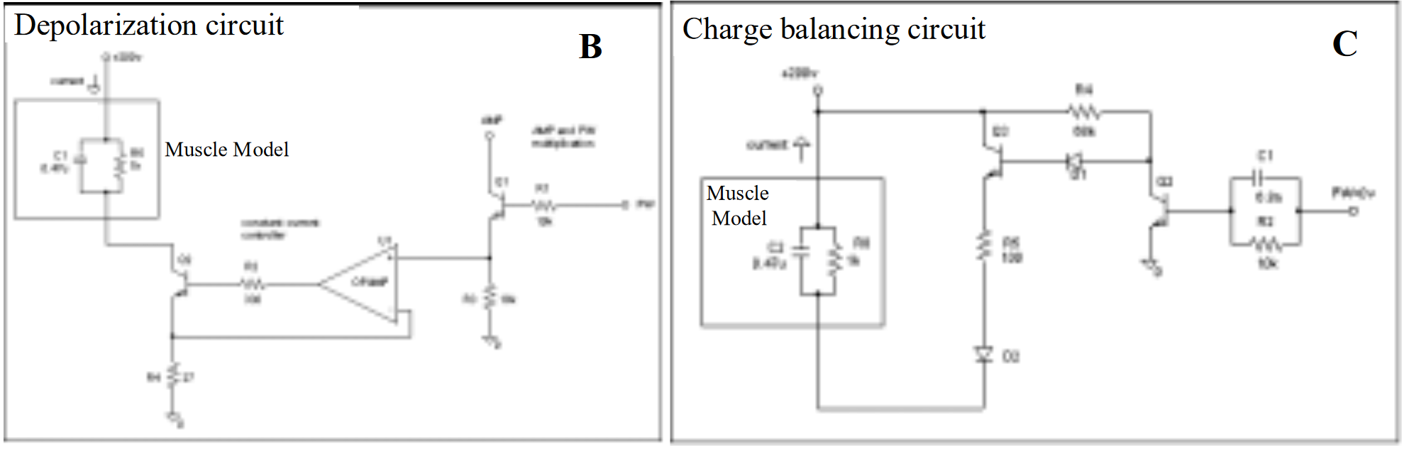
论文:T. Keller, “Surface functional electrical stimulation neuroprostheses for grasping,” Ph.D. dissertation, ETHZ, 2001.中设计的电荷平衡的双相电刺激器电路图
原文描述为:
The stimulation pulses for all four stimulation channels are generated from a single voltage regulated constant current controller. The controller has two inputs: one input controls the pulse amplitude and the other one controls the pulse width.
The transistor output is used as a reference for the closed loop voltage regulated current controller to regulate the depolarizing stimulation pulse (see scheme B in Figure 16). The charge balancing stimulation pulse is generated as follows: Immediately after the depolarization pulse a second open loop voltage to current converter allows an inverse current flow with an exponential curve shape that balances the charge in the stimulated muscles (see scheme C in Figure 16). The curve has its shape from a discharging capacitor that is charged during the depolarization pulse. As a result the entire stimulation current pulse form is composed of a depolarizing rectangular current pulse with constant amplitude followed by a hyperpolarizing exponentially decreasing current pulse that balances the charge (see Figure 15).
翻译:
所有四个刺激通道的刺激脉冲均由单个电压调节恒流控制器生成。该控制器有两个输入:一个输入控制脉冲幅度(VCC),另一个输入控制脉冲宽度(PW)。
晶体管输出用作闭环电压调节电流控制器的参考,以调节去极化刺激脉冲(见图 16 中的方案 B)。电荷平衡刺激脉冲的产生方式如下:在去极化脉冲之后,第二个开环电压到电流转换器立即允许具有指数曲线形状的反向电流流动,以平衡受刺激肌肉中的电荷(见图 16 中的方案 C)。曲线的形状来自在去极化脉冲期间充电的放电电容器。因此,整个刺激电流脉冲形式由幅度恒定的去极化矩形电流脉冲和随后的平衡电荷的超极化指数下降电流脉冲组成(见图 15)。
论文:Brunetti F, Garay A, Moreno J C, et al. Enhancing functional electrical stimulation for emerging rehabilitation robotics in the framework of hyper project[C]//2011 IEEE International Conference on Rehabilitation Robotics. IEEE, 2011: 1-6.
原文:In a previous section, the importance of balanced charge biphasic waveform was stated. To achieve this goal, Keller proposed a two staget circuit with two different working phases, [10]. During the first phase, the phase of active stimulation of the system, an operational amplifier controls the current across the load connected to a high voltage source. During the second phase, a passive discharge circuit, which appears in the upper part of figure 3, removes the electric charges from the electrodes-skin-muscle interfaces, previously inserted during the active phase. This is a very interesting solution but it struggles the chance of modifying actively the waveforms of the discharging periods.
翻译:在上一节中,我们阐述了平衡电荷双相波形的重要性。为了实现这一目标,Keller 提出了一种具有两个不同工作阶段的两级电路 [10]。在第一阶段,即系统主动刺激阶段,运算放大器控制连接到高压源的负载上的电流。在第二阶段,图 3 上部的被动放电电路会从先前在主动阶段插入的电极-皮肤-肌肉界面中移除电荷。这是一个非常有趣的解决方案,但它很难主动修改放电周期的波形。
电路分析
恒流源电路
https://blog.csdn.net/huxyc/article/details/126067167
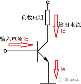
三极管
具体电路
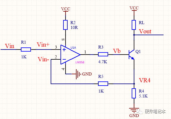
电阻R2起到对运放的保护作用,这个值不能太大,一般取值10R左右。(一点小经验吧,我们设计的产品中一般都有加);
电阻R3为三极管提供一个基极电流;
电阻R4位采样电阻,RL为负载电阻;
电阻R5起缓冲限流的作用,一般选取1K~100K之间(也有些电路没加这个电阻);
三极管Q1为NPN类型,需根据实际应用场合选择电压、电流的合适的三极管。
电路分析
假如我们要实现输出1mA的恒定电流,
设Vin=5V,R4=5.1K
根据虚断,Vin=Vin+;VR4 = Vin-
根据虚短,Vin+= Vin-=Vin
输出电流: IR4= VR4/R4 = 5V/5.1K = 1mA
可算出三极管基极电压为 VB = VR4+0.7V = 5.7V
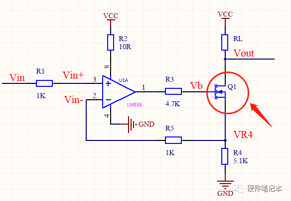
电路缺点
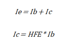
虽然,三极管发射极电流与集电极电流近似相等,但实际上,发射极的电流还包含了基极电流。
可以看出,运放输出级使用三极管时,输出电流会产生基极电流分量这一误差。如果此时还不满足电路精度要求,可将三极管改成MOS管。
MOS管属于压控器件,栅极需要的电流很小。IRL和IR4可以非常的接近,相比三极管而言,电流的精度提升了。
电路总结
简化电路,取出其中刺激部分,发现它是一个恒流源电路
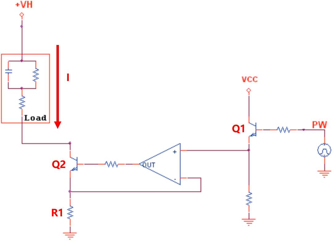
当PW输出高电平时,Q1导通,放大器正极电压近似为VCC,根据虚短,放大器负极电压和正极电压相等,由因为放大器负极接在电阻R1一段,故R1电压近似为VCC,已知R1电阻,故负载电流 I 确定为VCC/R1。
当PW输出低电平,Q1关断,放大器正极电压接地为零,故负载电流I为0,而电荷平衡电路在这时起到作用,消除电荷。
电荷平衡电路
通常对负载输出反向脉冲消除电荷,保证电荷平衡,减少人体肌肉组织损伤。
简化电路
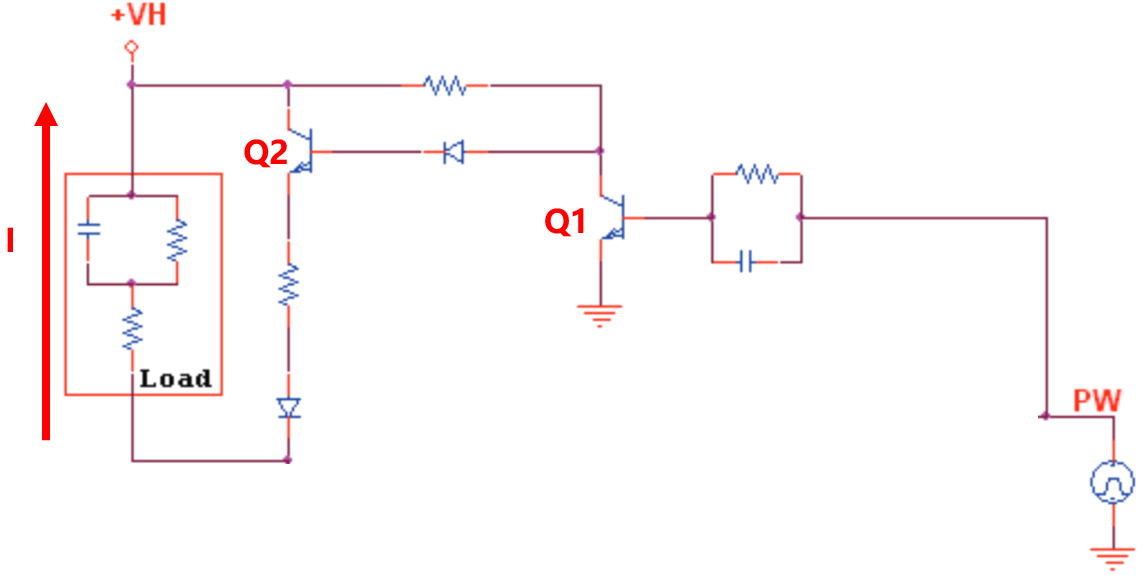
分析
当PW输出高电平的时候,三极管Q1导通,因三极管Q2基极与Q1集电极相连,故Q2集电极为低电平,故Q2断开,此时恒流源部分输出电流,在负载上产生正相脉冲
当PW输出低电平时,三极管Q1断开,Q2基极连接+VH电源,故Q2导通,又因电路中存在二极管,具有单向导电性,故电流的流向如图所示,与电刺激脉冲相反,这时消除人体负载(存在电容)中的电荷,起到平衡电荷的作用。
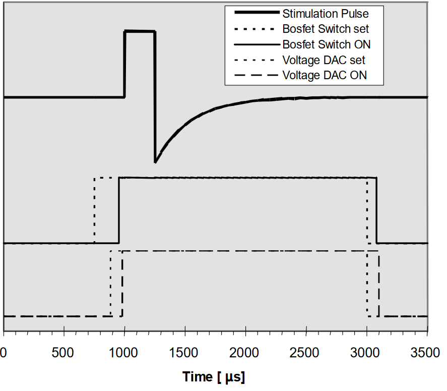
刺激效果如图:


 211
211

 被折叠的 条评论
为什么被折叠?
被折叠的 条评论
为什么被折叠?
 到【灌水乐园】发言


