


引脚信息:
| stm32f407 | OV2640 |
|---|---|
| 3.3V | VCC |
| PG15 | RST |
| PG9 | PWDN |
| PA4 | HREF |
| PD7 | SCCB_SDA (开漏输出,上拉,开漏输出的时候(=1), 也可以读取外部信号的高低电平) |
| PD6 | SCCB_SCL (推挽输出) |
| PC6 | D0(DCMI) |
| PC7 | D1(DCMI) |
| PC8 | D2(DCMI) |
| PC9 | D3(DCMI) |
| PC11 | D4(DCMI) |
| PB6 | D5(DCMI) |
| PE5 | D6(DCMI) |
| PE6 | D7(DCMI) |
| PA6 | CLK |
| PG9 | PWDN |
| PB7 | VSYNC |
| PA8 | XCLK(NC) |
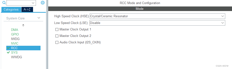
一、STM32CUBEMX的配置
使能RCC、SYS常规配置
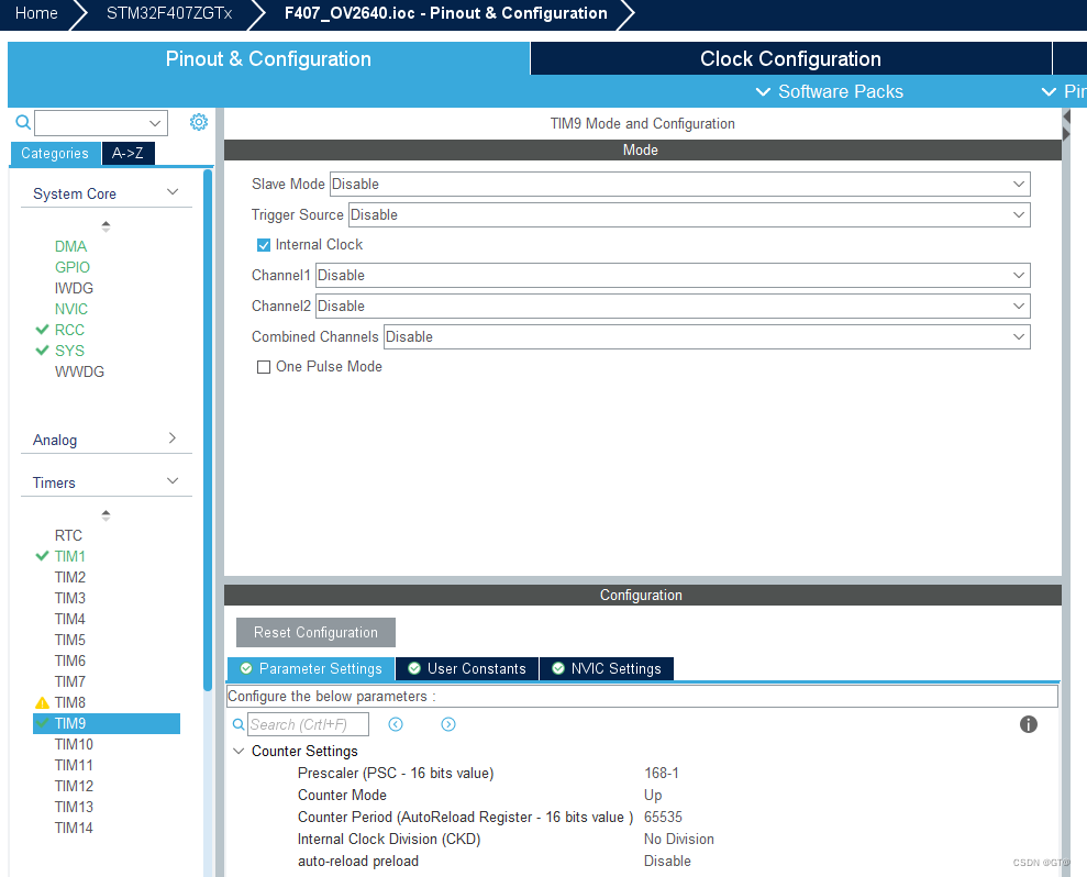
TIM9用做微秒延时定时器
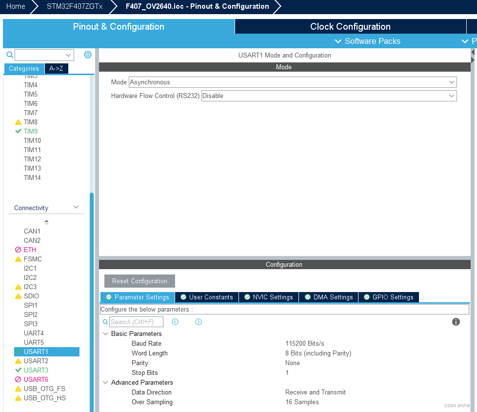
串口1用做打印输出
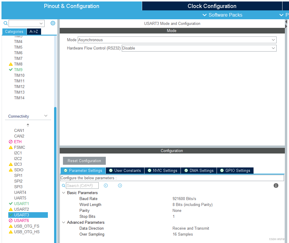
串口3用做DCMI数据传输到上位机
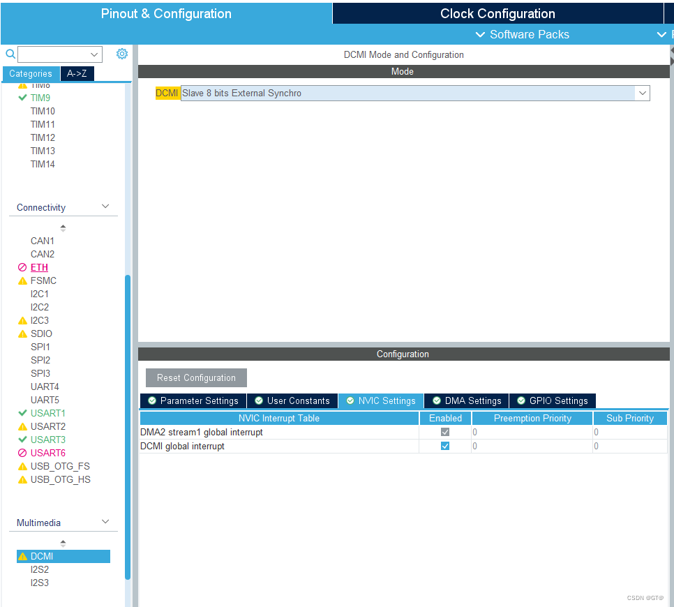
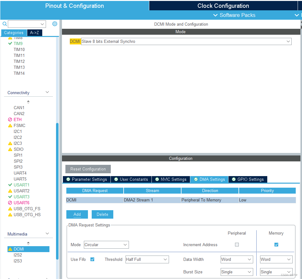
DCMI的配置
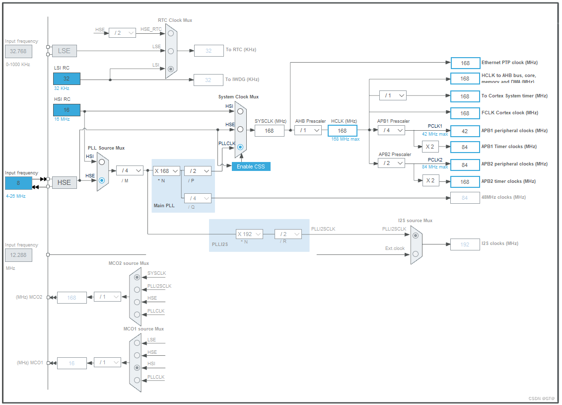
时钟树:

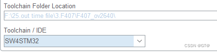
选择SW4STM32用CLION打开
二、使用步骤
1.移植OV2640驱动
驱动代码几乎来自正点原子例程:
ov2640.c:
#include "main.h"
#include "sccb.h"
#include "ov2640.h"
#include "ov2640cfg.h"
#include "usart.h"
#include "tim.h"
/**
* @brief OV2640 读寄存器
* @param reg : 寄存器地址
* @retval 读到的寄存器值
*/
uint8_t ov2640_read_reg(uint16_t reg) {
uint8_t data = 0;
sccb_start(); /* 启动SCCB传输 */
sccb_send_byte(OV2640_ADDR); /* 写器件ADDR */
delay_us(100);
sccb_send_byte(reg); /* 写寄存器地址 */
delay_us(100);
sccb_stop();
delay_us(100);
/* 设置寄存器地址后,才是读 */
sccb_start();
sccb_send_byte(OV2640_ADDR | 0x01); /* 发送读命令 */
delay_us(100);
data = sccb_read_byte(); /* 读取数据 */
sccb_nack();
sccb_stop();
return data;
}
/**
* @brief OV2640 写寄存器
* @param reg : 寄存器地址
* @param data: 要写入寄存器的值
* @retval 0, 成功; 1, 失败;
*/
uint8_t ov2640_write_reg(uint16_t reg, uint8_t data) {
uint8_t res = 0;
sccb_start(); /* 启动SCCB传输 */
delay_us(100);
if (sccb_send_byte(OV2640_ADDR))res = 1;/* 写器件ID */
delay_us(100);
if (sccb_send_byte(reg))res = 1; /* 写寄存器地址 */
delay_us(100);
if (sccb_send_byte(data))res = 1; /* 写数据 */
delay_us(100);
sccb_stop();
return res;
}
/**
* @brief 初始化 OV2640
* @param 无
* @retval 0, 成功; 1, 失败;
*/
uint8_t ov2640_init(void) {
uint16_t i = 0;
uint16_t reg;
OV2640_PWDN(0);
HAL_Delay(10);
OV2640_RST(0);
/* 必须先拉低OV2640的RST脚,再上电 */
HAL_Delay(20);
OV2640_RST(1); /* 结束复位 */
HAL_Delay(20);
sccb_init(); /* 初始化SCCB 的IO口 */
HAL_Delay(5);
ov2640_write_reg(OV2640_DSP_RA_DLMT, 0x01); /* 操作sensor寄存器 */
ov2640_write_reg(OV2640_SENSOR_COM7, 0x80); /* 软复位OV2640 */
HAL_Delay(50);
reg = ov2640_read_reg(OV2640_SENSOR_MIDH); /* 读取厂家ID 高八位 */
reg <<= 8;
reg |= ov2640_read_reg(OV2640_SENSOR_MIDL); /* 读取厂家ID 低八位 */
if (reg != OV2640_MID) /* ID 是否正常 */
{
printf("MID:%d\r\n", reg);
return 1; /* 失败 */
}
reg = ov2640_read_reg(OV2640_SENSOR_PIDH); /* 读取厂家ID 高八位 */
reg <<= 8;
reg |= ov2640_read_reg(OV2640_SENSOR_PIDL); /* 读取厂家ID 低八位 */
if (reg != OV2640_PID) /* ID是否正常 */
{
printf("HID:%d\r\n", reg);
return 1; /* 失败 */
}
/* 初始化 OV2640 */
for (i = 0; i < sizeof(ov2640_uxga_init_reg_tbl) / 2; i++) {
ov2640_write_reg(ov2640_uxga_init_reg_tbl[i][0], ov2640_uxga_init_reg_tbl[i][1]);
}
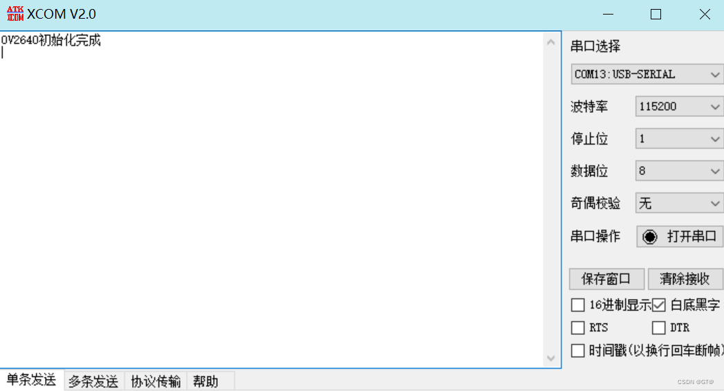
printf("OV2640初始化完成\r\n");
return 0; /* OV2640初始化完成 */
}
/**
* @brief OV2640 切换为JPEG模式
* @param 无
* @retval 无
*/
void ov2640_jpeg_mode(void) {
uint16_t i = 0;
/* 设置:YUV422格式 */
for (i = 0; i < (sizeof(ov2640_yuv422_reg_tbl) / 2); i++) {
ov2640_write_reg(ov2640_yuv422_reg_tbl[i][0], ov2640_yuv422_reg_tbl[i][1]); /* 发送配置数组 */
}
/* 设置:输出JPEG数据 */
for (i = 0; i < (sizeof(ov2640_jpeg_reg_tbl) / 2); i++) {
ov2640_write_reg(ov2640_jpeg_reg_tbl[i][0], ov2640_jpeg_reg_tbl[i][1]); /* 发送配置数组 */
}
}
/**
* @brief OV2640 切换为RGB565模式
* @param 无
* @retval 无
*/
void ov2640_rgb565_mode(void) {
uint16_t i = 0;
/* 设置:RGB565输出 */
for (i = 0; i < (sizeof(ov2640_rgb565_reg_tbl) / 4); i++) {
ov2640_write_reg(ov2640_rgb565_reg_tbl[i][0], ov2640_rgb565_reg_tbl[i][1]); /* 发送配置数组 */
}
}
/* 自动曝光设置参数表,支持5个等级 */
const static uint8_t OV2640_AUTOEXPOSURE_LEVEL[5][8] =
{
{
0xFF, 0x01,
0x24, 0x20,
0x25, 0x18,
0x26, 0x60,
},
{
0xFF, 0x01,
0x24, 0x34,
0x25, 0x1c,
0x26, 0x00,
},
{
0xFF, 0x01,
0x24, 0x3e,
0x25, 0x38,
0x26, 0x81,
},
{
0xFF, 0x01,
0x24, 0x48,
0x25, 0x40,
0x26, 0x81,
},
{
0xFF, 0x01,
0x24, 0x58,
0x25, 0x50,
0x26, 0x92,
},
};
/**
* @brief OV2640 EV曝光补偿
* @param level : 0~4
* @retval 无
*/
void ov2640_auto_exposure(uint8_t level) {
uint8_t i;
uint8_t *p = (uint8_t *) OV2640_AUTOEXPOSURE_LEVEL[level];
for (i = 0; i < 4; i++) {
ov2640_write_reg(p[i * 2], p[i * 2 + 1]);
}
}
/**
* @brief OV2640 白平衡设置
* @param mode : 0~4, 白平衡模式
* @arg 0: 自动 auto
* @arg 1: 日光 sunny
* @arg 2: 办公室 office
* @arg 3: 阴天 cloudy
* @arg 4: 家里 home
* @retval 无
*/
void ov2640_light_mode(uint8_t mode) {
uint8_t regccval = 0x5E;/* Sunny */
uint8_t regcdval = 0x41;
uint8_t regceval = 0x54;
switch (mode) {
case 0: /* auto */
ov2640_write_reg(0xFF, 0x00);
ov2640_write_reg(0xC7, 0x00); /* AWB ON */
return;
case 2: /* cloudy */
regccval = 0x65;
regcdval = 0x41;
regceval = 0x4F;
break;
case 3: /* office */
regccval = 0x52;
regcdval = 0x41;
regceval = 0x66;
break;
case 4: /* home */
regccval = 0x42;
regcdval = 0x3F;
regceval = 0x71;
break;
default :
break;
}
ov2640_write_reg(0xFF, 0x00);
ov2640_write_reg(0xC7, 0x40); /* AWB OFF */
ov2640_write_reg(0xCC, regccval);
ov2640_write_reg(0xCD, regcdval);
ov2640_write_reg(0xCE, regceval);
}
/**
* @brief OV2640 色彩饱和度设置
* @param set : 0~4, 代表色彩饱和度 -2 ~ 2.
* @retval 无
*/
void ov2640_color_saturation(uint8_t sat) {
uint8_t reg7dval = ((sat + 2) << 4) | 0x08;
ov2640_write_reg(0xFF, 0x00);
ov2640_write_reg(0x7C, 0x00);
ov2640_write_reg(0x7D, 0x02);
ov2640_write_reg(0x7C, 0x03);
ov2640_write_reg(0x7D, reg7dval);
ov2640_write_reg(0x7D, reg7dval);
}
/**
* @brief OV2640 亮度设置
* @param bright : 0~5, 代表亮度 -2 ~ 2.
* @retval 无
*/
void ov2640_brightness(uint8_t bright) {
ov2640_write_reg(0xff, 0x00);
ov2640_write_reg(0x7c, 0x00);
ov2640_write_reg(0x7d, 0x04);
ov2640_write_reg(0x7c, 0x09);
ov2640_write_reg(0x7d, bright << 4);
ov2640_write_reg(0x7d, 0x00);
}
/**
* @brief OV2640 对比度设置
* @param contrast : 0~4, 代表对比度 -2 ~ 2.
* @retval 无
*/
void ov2640_contrast(uint8_t contrast) {
uint8_t reg7d0val = 0x20; /* 默认为普通模式 */
uint8_t reg7d1val = 0x20;
switch (contrast) {
case 0:
reg7d0val = 0x18; /* -2 */
reg7d1val = 0x34;
break;
case 1:
reg7d0val = 0x1C; /* -1 */
reg7d1val = 0x2A;
break;
case 3:
reg7d0val = 0x24; /* 1 */
reg7d1val = 0x16;
break;
case 4:
reg7d0val = 0x28; /* 2 */
reg7d1val = 0x0C;
break;
default :
break;
}
ov2640_write_reg(0xff, 0x00);
ov2640_write_reg(0x7c, 0x00);
ov2640_write_reg(0x7d, 0x04);
ov2640_write_reg(0x7c, 0x07);
ov2640_write_reg(0x7d, 0x20);
ov2640_write_reg(0x7d, reg7d0val);
ov2640_write_reg(0x7d, reg7d1val);
ov2640_write_reg(0x7d, 0x06);
}
/**
* @brief OV2640 特效设置
* @param eft : 0~6, 特效效果
* @arg 0: 正常
* @arg 1: 负片
* @arg 2: 黑白
* @arg 3: 偏红色
* @arg 4: 偏绿色
* @arg 5: 偏蓝色
* @arg 6: 复古
* @retval 无
*/
void ov2640_special_effects(uint8_t eft) {
uint8_t reg7d0val = 0x00; /* 默认为普通模式 */
uint8_t reg7d1val = 0x80;
uint8_t reg7d2val = 0x80;
switch (eft) {
case 1: /* 负片 */
reg7d0val = 0x40;
break;
case 2: /* 黑白 */
reg7d0val = 0x18;
break;
case 3: /* 偏红色 */
reg7d0val = 0x18;
reg7d1val = 0x40;
reg7d2val = 0xC0;
break;
case 4: /* 偏绿色 */
reg7d0val = 0x18;
reg7d1val = 0x40;
reg7d2val = 0x40;
break;
case 5: /* 偏蓝色 */
reg7d0val = 0x18;
reg7d1val = 0xA0;
reg7d2val = 0x40;
break;
case 6: /* 复古 */
reg7d0val = 0x18;
reg7d1val = 0x40;
reg7d2val = 0xA6;
break;
}
ov2640_write_reg(0xff, 0x00);
ov2640_write_reg(0x7c, 0x00);
ov2640_write_reg(0x7d, reg7d0val);
ov2640_write_reg(0x7c, 0x05);
ov2640_write_reg(0x7d, reg7d1val);
ov2640_write_reg(0x7d, reg7d2val);
}
/**
* @brief OV2640 彩条测试
* @param mode : 0~2
* @arg 0: 关闭
* @arg 1: 彩条
* @retval 无
*/
void ov2640_color_bar(uint8_t mode) {
uint8_t reg;
ov2640_write_reg(0xFF, 0x01);
reg = ov2640_read_reg(0x12);
reg &= ~(1 << 1);
if (mode)reg |= 1 << 1;
ov2640_write_reg(0x12, reg);
}
/**
* @bref 设置传感器输出窗口
* @param sx : 起始地址x
* @param sy : 起始地址y
* @param width : 宽度(对应:horizontal)
* @param hight : 高度(对应:vertical)
* @retval 无
*/
void ov2640_window_set(uint16_t sx, uint16_t sy, uint16_t width, uint16_t height) {
uint16_t endx;
uint16_t endy;
uint8_t temp;
endx = sx + width / 2;
endy = sy + height / 2;
ov2640_write_reg(0xFF, 0x01);
temp = ov2640_read_reg(0x03); /* 读取Vref之前的值 */
temp &= 0xF0;
temp |= ((endy & 0x03) << 2) | (sy & 0x03);
ov2640_write_reg(0x03, temp); /* 设置Vref的start和end的最低2位 */
ov2640_write_reg(0x19, sy >> 2); /* 设置Vref的start高8位 */
ov2640_write_reg(0x1A, endy >> 2); /* 设置Vref的end的高8位 */
temp = ov2640_read_reg(0x32); /* 读取Href之前的值 */
temp &= 0xC0;
temp |= ((endx & 0x07) << 3) | (sx & 0x07);
ov2640_write_reg(0x32, temp); /* 设置Href的start和end的最低3位 */
ov2640_write_reg(0x17, sx >> 3); /* 设置Href的start高8位 */
ov2640_write_reg(0x18, endx >> 3); /* 设置Href的end的高8位 */
}
/**
* @bref 设置图像输出大小
* @@param width : 宽度(对应:horizontal)
* @param height: 高度(对应:vertical)
* @note OV2640输出图像的大小(分辨率),完全由该函数确定
* width和height必须是4的倍数
* @retval 0 : 设置成功
* 其他 : 设置失败
*/
uint8_t ov2640_outsize_set(uint16_t width, uint16_t height) {
uint16_t outh;
uint16_t outw;
uint8_t temp;
if (width % 4) return 1;
if (height % 4) return 2;
outw = width / 4;
outh = height / 4;
ov2640_write_reg(0xFF, 0x00);
ov2640_write_reg(0xE0, 0x04);
ov2640_write_reg(0x5A, outw & 0xFF); /* 设置OUTW的低八位 */
ov2640_write_reg(0x5B, outh & 0xFF); /* 设置OUTH的低八位 */
temp = (outw >> 8) & 0x03;
temp |= (outh >> 6) & 0x04;
ov2640_write_reg(0x5C, temp); /* 设置OUTH/OUTW的高位 */
ov2640_write_reg(0xE0, 0x00);
return 0;
}
/**
* @brief 设置图像开窗大小
* @note OV2640输出图像的大小(分辨率),完全由该函数确定
* 由于开启了scale功能,用于输出的图像窗口为: xsize - 2 * offx, ysize - 2 * offy
* 实际输出(width,height), 是在: xsize - 2 * offx, ysize - 2 * offy的基础上进行缩放处理.
* 一般设置offx和offy的值为16和4,更小也是可以,不过默认是16和4
* @param offx,offy : 输出图像在ov2640_image_window_set设定窗口(假设长宽为xsize和ysize)上的偏移
* @param width,height : 实际输出图像的宽度和高度,必须是4的倍数
* @retval 0, 成功; 其他, 失败;
*/
uint8_t ov2640_image_win_set(uint16_t offx, uint16_t offy, uint16_t width, uint16_t height) {
uint16_t hsize;
uint16_t vsize;
uint8_t temp;
if (width % 4) return 1;
if (height % 4) return 2;
hsize = width / 4;
vsize = height / 4;
ov2640_write_reg(0xFF, 0x00);
ov2640_write_reg(0xE0, 0x04);
ov2640_write_reg(0x51, hsize & 0xFF); /* 设置H_SIZE的低八位 */
ov2640_write_reg(0x52, vsize & 0xFF); /* 设置V_SIZE的低八位 */
ov2640_write_reg(0x53, offx & 0xFF); /* 设置offx的低八位 */
ov2640_write_reg(0x54, offy & 0xFF); /* 设置offy的低八位 */
temp = (vsize >> 1) & 0x80;
temp |= (offy >> 4) & 0x70;
temp |= (hsize >> 5) & 0x08;
temp |= (offx >> 8) & 0x07;
ov2640_write_reg(0x55, temp); /* 设置H_SIZE/V_SIZE/OFFX,OFFY的高位 */
ov2640_write_reg(0x57, (hsize >> 2) & 0x80); /* 设置H_SIZE/V_SIZE/OFFX,OFFY的高位 */
ov2640_write_reg(0xE0, 0x00);
return 0;
}
/**
* @bref 该函数设置图像尺寸大小,也就是所选格式的输出分辨率
* @note UXGA:1600*1200,SVGA:800*600,CIF:352*288
* @param width : 图像宽度
* @param height : 图像高度
*
* @retval 0 : 设置成功
* 其他 : 设置失败
*/
uint8_t ov2640_imagesize_set(uint16_t width, uint16_t height) {
uint8_t temp;
ov2640_write_reg(0xFF, 0x00);
ov2640_write_reg(0xE0, 0x04);
ov2640_write_reg(0xC0, (width) >> 3 & 0xFF); /* 设置HSIZE的10:3位 */
ov2640_write_reg(0xC1, (height) >> 3 & 0xFF); /* 设置VSIZE的10:3位 */
temp = (width & 0x07) << 3;
temp |= height & 0x07;
temp |= (width >> 4) & 0x80;
ov2640_write_reg(0x8C, temp);
ov2640_write_reg(0xE0, 0x00);
return 0;
}
/**
* @bref 闪光灯外部信号控制
* @param sw : 0,关闭
* 1,打开
* @retval 无
*/
void ov2640_flash_extctrl(uint8_t sw) {
if (sw) OV2640_FLASH(1);
else
OV2640_FLASH(0);
}
/**
* @bref 闪光灯内部信号控制
* @note 控制信号从OV2640的STROBE引脚自动输出
* @retval 无
*/
void ov2640_flash_intctrl(void) {
ov2640_write_reg(0xFF, 0x01);
ov2640_write_reg(0x4B, 0x81);
ov2640_write_reg(0x4B, 0x01);
}
ov2640.h:
#ifndef _OV2640_H
#define _OV2640_H

#include "main.h"


/******************************************************************************************/
/* PWDN 引脚定义 */
#define OV_PWDN_GPIO_PORT               GPIOG
#define OV_PWDN_GPIO_PIN                GPIO_PIN_9
#define OV_PWDN_GPIO_CLK_ENABLE()       do{ __HAL_RCC_GPIOG_CLK_ENABLE(); }while(0)   /* PG口时钟使能 */

/* RESET 引脚定义 */
#define OV_RESET_GPIO_PORT              GPIOG
#define OV_RESET_GPIO_PIN               GPIO_PIN_15
#define OV_RESET_GPIO_CLK_ENABLE()      do{ __HAL_RCC_GPIOG_CLK_ENABLE(); }while(0)   /* PG口时钟使能 */

/* FLASH 引脚定义 */
#define OV_FLASH_GPIO_PORT              GPIOA
#define OV_FLASH_GPIO_PIN               GPIO_PIN_8
#define OV_FLASH_GPIO_CLK_ENABLE()      do{ __HAL_RCC_GPIOA_CLK_ENABLE(); }while(0)   /* PA口时钟使能 */

/******************************************************************************************/

/* IO控制函数 */
#define OV2640_PWDN(x)      do{ x ? \
                                HAL_GPIO_WritePin(OV_PWDN_GPIO_PORT, OV_PWDN_GPIO_PIN, GPIO_PIN_SET) : \
                                HAL_GPIO_WritePin(OV_PWDN_GPIO_PORT, OV_PWDN_GPIO_PIN, GPIO_PIN_RESET); \
                            }while(0)       /* POWER DOWN控制信号 */

#define OV2640_RST(x)       do{ x ? \
                                HAL_GPIO_WritePin(OV_RESET_GPIO_PORT, OV_RESET_GPIO_PIN, GPIO_PIN_SET) : \
                                HAL_GPIO_WritePin(OV_RESET_GPIO_PORT, OV_RESET_GPIO_PIN, GPIO_PIN_RESET); \
                            }while(0)       /* 复位控制信号 */

#define OV2640_FLASH(x)     do{ x ? \
                                HAL_GPIO_WritePin(OV_FLASH_GPIO_PORT, OV_FLASH_GPIO_PIN, GPIO_PIN_SET) : \
                                HAL_GPIO_WritePin(OV_FLASH_GPIO_PORT, OV_FLASH_GPIO_PIN, GPIO_PIN_RESET); \
                            }while(0)       /* 闪光灯控制信号 */

#define Image_FlipVer       1               /* 图像垂直翻转使能 1;使能 0:失能(使用ATK-OV2640模组版本必须使能) */

/* OV2640的ID和访问地址 */
#define OV2640_MID          0x7FA2
#define OV2640_PID          0x2642
#define OV2640_ADDR         0x60            /* OV2640的IIC地址 */


/* 当选择DSP地址(0xFF=0x00)时,OV2640的DSP寄存器地址映射表 */
#define OV2640_DSP_R_BYPASS     0x05
#define OV2640_DSP_Qs           0x44
#define OV2640_DSP_CTRL         0x50
#define OV2640_DSP_HSIZE1       0x51
#define OV2640_DSP_VSIZE1       0x52
#define OV2640_DSP_XOFFL        0x53
#define OV2640_DSP_YOFFL        0x54
#define OV2640_DSP_VHYX         0x55
#define OV2640_DSP_DPRP         0x56
#define OV2640_DSP_TEST         0x57
#define OV2640_DSP_ZMOW         0x5A
#define OV2640_DSP_ZMOH         0x5B
#define OV2640_DSP_ZMHH         0x5C
#define OV2640_DSP_BPADDR       0x7C
#define OV2640_DSP_BPDATA       0x7D
#define OV2640_DSP_CTRL2        0x86
#define OV2640_DSP_CTRL3        0x87
#define OV2640_DSP_SIZEL        0x8C
#define OV2640_DSP_HSIZE2       0xC0
#define OV2640_DSP_VSIZE2       0xC1
#define OV2640_DSP_CTRL0        0xC2
#define OV2640_DSP_CTRL1        0xC3
#define OV2640_DSP_R_DVP_SP     0xD3
#define OV2640_DSP_IMAGE_MODE   0xDA
#define OV2640_DSP_RESET        0xE0
#define OV2640_DSP_MS_SP        0xF0
#define OV2640_DSP_SS_ID        0x7F
#define OV2640_DSP_SS_CTRL      0xF8
#define OV2640_DSP_MC_BIST      0xF9
#define OV2640_DSP_MC_AL        0xFA
#define OV2640_DSP_MC_AH        0xFB
#define OV2640_DSP_MC_D         0xFC
#define OV2640_DSP_P_STATUS     0xFE
#define OV2640_DSP_RA_DLMT      0xFF

/* 当选择传感器地址(0xFF=0x01)时,OV2640的DSP寄存器地址映射表 */
#define OV2640_SENSOR_GAIN       0x00
#define OV2640_SENSOR_COM1       0x03
#define OV2640_SENSOR_REG04      0x04
#define OV2640_SENSOR_REG08      0x08
#define OV2640_SENSOR_COM2       0x09
#define OV2640_SENSOR_PIDH       0x0A
#define OV2640_SENSOR_PIDL       0x0B
#define OV2640_SENSOR_COM3       0x0C
#define OV2640_SENSOR_COM4       0x0D
#define OV2640_SENSOR_AEC        0x10
#define OV2640_SENSOR_CLKRC      0x11
#define OV2640_SENSOR_COM7       0x12
#define OV2640_SENSOR_COM8       0x13
#define OV2640_SENSOR_COM9       0x14
#define OV2640_SENSOR_COM10      0x15
#define OV2640_SENSOR_HREFST     0x17
#define OV2640_SENSOR_HREFEND    0x18
#define OV2640_SENSOR_VSTART     0x19
#define OV2640_SENSOR_VEND       0x1A
#define OV2640_SENSOR_MIDH       0x1C
#define OV2640_SENSOR_MIDL       0x1D
#define OV2640_SENSOR_AEW        0x24
#define OV2640_SENSOR_AEB        0x25
#define OV2640_SENSOR_W          0x26
#define OV2640_SENSOR_REG2A      0x2A
#define OV2640_SENSOR_FRARL      0x2B
#define OV2640_SENSOR_ADDVSL     0x2D
#define OV2640_SENSOR_ADDVHS     0x2E
#define OV2640_SENSOR_YAVG       0x2F
#define OV2640_SENSOR_REG32      0x32
#define OV2640_SENSOR_ARCOM2     0x34
#define OV2640_SENSOR_REG45      0x45
#define OV2640_SENSOR_FLL        0x46
#define OV2640_SENSOR_FLH        0x47
#define OV2640_SENSOR_COM19      0x48
#define OV2640_SENSOR_ZOOMS      0x49
#define OV2640_SENSOR_COM22      0x4B
#define OV2640_SENSOR_COM25      0x4E
#define OV2640_SENSOR_BD50       0x4F
#define OV2640_SENSOR_BD60       0x50
#define OV2640_SENSOR_REG5D      0x5D
#define OV2640_SENSOR_REG5E      0x5E
#define OV2640_SENSOR_REG5F      0x5F
#define OV2640_SENSOR_REG60      0x60
#define OV2640_SENSOR_HISTO_LOW  0x61
#define OV2640_SENSOR_HISTO_HIGH 0x62


/* 对外接口函数 */
uint8_t ov2640_read_reg(uint16_t reg);

uint8_t ov2640_write_reg(uint16_t reg, uint8_t data);

uint8_t ov2640_init(void);

void ov2640_jpeg_mode(void);

void ov2640_rgb565_mode(void);

void ov2640_auto_exposure(uint8_t level);

void ov2640_light_mode(uint8_t mode);

void ov2640_color_saturation(uint8_t sat);

void ov2640_brightness(uint8_t bright);

void ov2640_contrast(uint8_t contrast);

void ov2640_special_effects(uint8_t eft);

void ov2640_window_set(uint16_t sx, uint16_t sy, uint16_t width, uint16_t height);

uint8_t ov2640_outsize_set(uint16_t width, uint16_t height);

uint8_t ov2640_image_win_set(uint16_t offx, uint16_t offy, uint16_t width, uint16_t height);

uint8_t ov2640_image_window_set(uint16_t offx, uint16_t offy, uint16_t width, uint16_t height);

uint8_t ov2640_imagesize_set(uint16_t width, uint16_t height);

void ov2640_flash_extctrl(uint8_t sw);

void ov2640_flash_intctrl(void);

#endif
sccb.c
#include "sccb.h"
#include "tim.h"


/**
 * @brief       初始化SCCB
 * @param        SCCB_SCL-PD6(推挽输出)
 * @retval       SCCB_SDA-PD7(SDA引脚模式设置,开漏输出,上拉, 这样就不用再设置IO方向了, 开漏输出的时候(=1), 也可以读取外部信号的高低电平)
 */
void sccb_init(void) {

    sccb_stop();    /* 停止总线上所有设备 */
}

/**
 * @brief       SCCB延时函数,用于控制IIC读写速度
 * @param       无
 * @retval      无
 */
static void sccb_delay(void) {
    delay_us(50);
}

/**
 * @brief       产生SCCB起始信号
 * @param       无
 * @retval      无
 */
void sccb_start(void) {
    SCCB_SDA(1);
    SCCB_SCL(1);
    sccb_delay();
    SCCB_SDA(0);    /* START信号: 当SCL为高时, SDA从高变成低, 表示起始信号 */
    sccb_delay();
    SCCB_SCL(0);    /* 钳住SCCB总线,准备发送或接收数据 */
}

/**
 * @brief       产生SCCB停止信号
 * @param       无
 * @retval      无
 */
void sccb_stop(void) {
    SCCB_SDA(0);    /* STOP信号: 当SCL为高时, SDA从低变成高, 表示停止信号 */
    sccb_delay();
    SCCB_SCL(1);
    sccb_delay();
    SCCB_SDA(1);    /* 发送SCCB总线结束信号 */
    sccb_delay();
}

/**
 * @brief       不产生ACK应答
 * @param       无
 * @retval      无
 */
void sccb_nack(void) {
    sccb_delay();
    SCCB_SDA(1);    /* SCL 0 -> 1  时 SDA = 1, 表示不应答 */
    SCCB_SCL(1);
    sccb_delay();
    SCCB_SCL(0);    /* 产生一个时钟 */
    sccb_delay();
    SCCB_SDA(0);
    sccb_delay();
}

/**
 * @brief       SCCB  发送一个字节
 * @param       data: 要发送的数据
 * @retval      res
 */
uint8_t sccb_send_byte(uint8_t data) {
    uint8_t t, res;

    for (t = 0; t < 8; t++) {
        SCCB_SDA((data & 0x80) >> 7);   /* 高位先发送 */
        sccb_delay();
        SCCB_SCL(1);
        sccb_delay();
        SCCB_SCL(0);
        data <<= 1;     /* 左移1位,用于下一次发送 */
    }
#if OV_SCCB_TYPE_NOD
    SCCB_SDA_IN();      /* 设置SDA为输入 */
    sccb_delay();
#endif
    SCCB_SDA(1);        /* 发送完成, 主机释放SDA线 */
    sccb_delay();
    SCCB_SCL(1);        /* 接收第九位,以判断是否发送成功 */
    sccb_delay();

    if (SCCB_READ_SDA) {
        res = 1;        /* SDA=1发送失败,返回1 */
    } else {
        res = 0;        /* SDA=0发送成功,返回0 */
    }

    SCCB_SCL(0);
#if OV_SCCB_TYPE_NOD
    SCCB_SDA_OUT();      /* 设置SDA为输出 */
    delay_us(50);
#endif
    return res;
}

/**
 * @brief       SCCB 读取一个字节
 * @param       无
 * @retval      读取到的数据
 */
uint8_t sccb_read_byte(void) {
    uint8_t i, receive = 0;
#if OV_SCCB_TYPE_NOD
    SCCB_SDA_IN();          /* 设置SDA为输入 */
    delay_us(50);
#endif
    for (i = 0; i < 8; i++) /* 接收1个字节数据 */
    {
        sccb_delay();
        receive <<= 1;      /* 高位先输出,所以先收到的数据位要左移 */
        SCCB_SCL(1);

        if (SCCB_READ_SDA) {
            receive++;
        }
        sccb_delay();
        SCCB_SCL(0);
    }
#if OV_SCCB_TYPE_NOD
    SCCB_SDA_OUT();         /* 设置SDA为输出 */
    delay_us(50);
#endif
    return receive;
}
sccb.h
#ifndef __SCCB_H
#define __SCCB_H

#include "main.h"


/******************************************************************************************/
/* 引脚 定义 */

#define SCCB_SCL_GPIO_PORT               GPIOD
#define SCCB_SCL_GPIO_PIN                GPIO_PIN_6
#define SCCB_SCL_GPIO_CLK_ENABLE()       do{ __HAL_RCC_GPIOD_CLK_ENABLE(); }while(0)        /* PD口时钟使能 */

#define SCCB_SDA_GPIO_PORT               GPIOD
#define SCCB_SDA_GPIO_PIN                GPIO_PIN_7
#define SCCB_SDA_GPIO_CLK_ENABLE()       do{ __HAL_RCC_GPIOG_CLK_ENABLE(); }while(0)        /* PG口时钟使能 */


#define OV_SCCB_TYPE_NOD     0          /* 如果不用开漏模式或SCCB上无上拉电阻,我们需要推挽和输入切换的方式 */
#if OV_SCCB_TYPE_NOD
#define SCCB_SDA_IN()  { GPIOD->MODER &= ~(3 << (7 * 2)); GPIOD->MODER |= 0 << (7 * 2); }   /* PD7 输入 */
#define SCCB_SDA_OUT() { GPIOD->MODER &= ~(3 << (7 * 2)); GPIOD->MODER |= 1 << (7 * 2); }   /* PD7 输出 */
#endif

/******************************************************************************************/

/* IO操作函数 */
#define SCCB_SCL(x)   do{ x ? \
                          HAL_GPIO_WritePin(SCCB_SCL_GPIO_PORT, SCCB_SCL_GPIO_PIN, GPIO_PIN_SET) : \
                          HAL_GPIO_WritePin(SCCB_SCL_GPIO_PORT, SCCB_SCL_GPIO_PIN, GPIO_PIN_RESET); \
                      }while(0)  /* SCL */

#define SCCB_SDA(x)   do{ x ? \
                          HAL_GPIO_WritePin(SCCB_SDA_GPIO_PORT, SCCB_SDA_GPIO_PIN, GPIO_PIN_SET) : \
                          HAL_GPIO_WritePin(SCCB_SDA_GPIO_PORT, SCCB_SDA_GPIO_PIN, GPIO_PIN_RESET); \
                      }while(0)  /* SDA */


#define SCCB_READ_SDA       HAL_GPIO_ReadPin(SCCB_SDA_GPIO_PORT, SCCB_SDA_GPIO_PIN)         /* 读取SDA */


/* 对外接口函数 */
void sccb_init(void);

void sccb_stop(void);

void sccb_start(void);

void sccb_nack(void);

uint8_t sccb_read_byte(void);

uint8_t sccb_send_byte(uint8_t data);

#endif
tim.c
/**
******************************************************************************
* @file tim.c
* @brief This file provides code for the configuration
* of the TIM instances.
******************************************************************************
* @attention
*
* <h2><center>© Copyright (c) 2023 STMicroelectronics.
* All rights reserved.</center></h2>
*
* This software component is licensed by ST under BSD 3-Clause license,
* the "License"; You may not use this file except in compliance with the
* License. You may obtain a copy of the License at:
* opensource.org/licenses/BSD-3-Clause
*
******************************************************************************
*/
/* Includes ------------------------------------------------------------------*/
#include "tim.h"
/* USER CODE BEGIN 0 */
/* USER CODE END 0 */
TIM_HandleTypeDef htim1;
TIM_HandleTypeDef htim9;
/* TIM1 init function */
void MX_TIM1_Init(void)
{
TIM_ClockConfigTypeDef sClockSourceConfig = {0};
TIM_MasterConfigTypeDef sMasterConfig = {0};
TIM_OC_InitTypeDef sConfigOC = {0};
TIM_BreakDeadTimeConfigTypeDef sBreakDeadTimeConfig = {0};
htim1.Instance = TIM1;
htim1.Init.Prescaler = 6720-1;
htim1.Init.CounterMode = TIM_COUNTERMODE_UP;
htim1.Init.Period = 250-1;
htim1.Init.ClockDivision = TIM_CLOCKDIVISION_DIV1;
htim1.Init.RepetitionCounter = 0;
htim1.Init.AutoReloadPreload = TIM_AUTORELOAD_PRELOAD_DISABLE;
if (HAL_TIM_Base_Init(&htim1) != HAL_OK)
{
Error_Handler();
}
sClockSourceConfig.ClockSource = TIM_CLOCKSOURCE_INTERNAL;
if (HAL_TIM_ConfigClockSource(&htim1, &sClockSourceConfig) != HAL_OK)
{
Error_Handler();
}
if (HAL_TIM_PWM_Init(&htim1) != HAL_OK)
{
Error_Handler();
}
sMasterConfig.MasterOutputTrigger = TIM_TRGO_RESET;
sMasterConfig.MasterSlaveMode = TIM_MASTERSLAVEMODE_DISABLE;
if (HAL_TIMEx_MasterConfigSynchronization(&htim1, &sMasterConfig) != HAL_OK)
{
Error_Handler();
}
sConfigOC.OCMode = TIM_OCMODE_PWM1;
sConfigOC.Pulse = 0;
sConfigOC.OCPolarity = TIM_OCPOLARITY_LOW;
sConfigOC.OCNPolarity = TIM_OCNPOLARITY_HIGH;
sConfigOC.OCFastMode = TIM_OCFAST_DISABLE;
sConfigOC.OCIdleState = TIM_OCIDLESTATE_RESET;
sConfigOC.OCNIdleState = TIM_OCNIDLESTATE_RESET;
if (HAL_TIM_PWM_ConfigChannel(&htim1, &sConfigOC, TIM_CHANNEL_1) != HAL_OK)
{
Error_Handler();
}
__HAL_TIM_DISABLE_OCxPRELOAD(&htim1, TIM_CHANNEL_1);
if (HAL_TIM_PWM_ConfigChannel(&htim1, &sConfigOC, TIM_CHANNEL_2) != HAL_OK)
{
Error_Handler();
}
if (HAL_TIM_PWM_ConfigChannel(&htim1, &sConfigOC, TIM_CHANNEL_3) != HAL_OK)
{
Error_Handler();
}
sBreakDeadTimeConfig.OffStateRunMode = TIM_OSSR_DISABLE;
sBreakDeadTimeConfig.OffStateIDLEMode = TIM_OSSI_DISABLE;
sBreakDeadTimeConfig.LockLevel = TIM_LOCKLEVEL_OFF;
sBreakDeadTimeConfig.DeadTime = 0;
sBreakDeadTimeConfig.BreakState = TIM_BREAK_DISABLE;
sBreakDeadTimeConfig.BreakPolarity = TIM_BREAKPOLARITY_HIGH;
sBreakDeadTimeConfig.AutomaticOutput = TIM_AUTOMATICOUTPUT_DISABLE;
if (HAL_TIMEx_ConfigBreakDeadTime(&htim1, &sBreakDeadTimeConfig) != HAL_OK)
{
Error_Handler();
}
HAL_TIM_MspPostInit(&htim1);
}
/* TIM9 init function */
void MX_TIM9_Init(void)
{
TIM_ClockConfigTypeDef sClockSourceConfig = {0};
htim9.Instance = TIM9;
htim9.Init.Prescaler = 168-1;
htim9.Init.CounterMode = TIM_COUNTERMODE_UP;
htim9.Init.Period = 65535;
htim9.Init.ClockDivision = TIM_CLOCKDIVISION_DIV1;
htim9.Init.AutoReloadPreload = TIM_AUTORELOAD_PRELOAD_DISABLE;
if (HAL_TIM_Base_Init(&htim9) != HAL_OK)
{
Error_Handler();
}
sClockSourceConfig.ClockSource = TIM_CLOCKSOURCE_INTERNAL;
if (HAL_TIM_ConfigClockSource(&htim9, &sClockSourceConfig) != HAL_OK)
{
Error_Handler();
}
}
void HAL_TIM_Base_MspInit(TIM_HandleTypeDef* tim_baseHandle)
{
if(tim_baseHandle->Instance==TIM1)
{
/* USER CODE BEGIN TIM1_MspInit 0 */
/* USER CODE END TIM1_MspInit 0 */
/* TIM1 clock enable */
__HAL_RCC_TIM1_CLK_ENABLE();
/* USER CODE BEGIN TIM1_MspInit 1 */
/* USER CODE END TIM1_MspInit 1 */
}
else if(tim_baseHandle->Instance==TIM9)
{
/* USER CODE BEGIN TIM9_MspInit 0 */
/* USER CODE END TIM9_MspInit 0 */
/* TIM9 clock enable */
__HAL_RCC_TIM9_CLK_ENABLE();
/* USER CODE BEGIN TIM9_MspInit 1 */
/* USER CODE END TIM9_MspInit 1 */
}
}
void HAL_TIM_MspPostInit(TIM_HandleTypeDef* timHandle)
{
GPIO_InitTypeDef GPIO_InitStruct = {0};
if(timHandle->Instance==TIM1)
{
/* USER CODE BEGIN TIM1_MspPostInit 0 */
/* USER CODE END TIM1_MspPostInit 0 */
__HAL_RCC_GPIOE_CLK_ENABLE();
/**TIM1 GPIO Configuration
PE9 ------> TIM1_CH1
PE11 ------> TIM1_CH2
PE13 ------> TIM1_CH3
*/
GPIO_InitStruct.Pin = GPIO_PIN_9|GPIO_PIN_11|GPIO_PIN_13;
GPIO_InitStruct.Mode = GPIO_MODE_AF_PP;
GPIO_InitStruct.Pull = GPIO_NOPULL;
GPIO_InitStruct.Speed = GPIO_SPEED_FREQ_LOW;
GPIO_InitStruct.Alternate = GPIO_AF1_TIM1;
HAL_GPIO_Init(GPIOE, &GPIO_InitStruct);
/* USER CODE BEGIN TIM1_MspPostInit 1 */
/* USER CODE END TIM1_MspPostInit 1 */
}
}
void HAL_TIM_Base_MspDeInit(TIM_HandleTypeDef* tim_baseHandle)
{
if(tim_baseHandle->Instance==TIM1)
{
/* USER CODE BEGIN TIM1_MspDeInit 0 */
/* USER CODE END TIM1_MspDeInit 0 */
/* Peripheral clock disable */
__HAL_RCC_TIM1_CLK_DISABLE();
/* USER CODE BEGIN TIM1_MspDeInit 1 */
/* USER CODE END TIM1_MspDeInit 1 */
}
else if(tim_baseHandle->Instance==TIM9)
{
/* USER CODE BEGIN TIM9_MspDeInit 0 */
/* USER CODE END TIM9_MspDeInit 0 */
/* Peripheral clock disable */
__HAL_RCC_TIM9_CLK_DISABLE();
/* USER CODE BEGIN TIM9_MspDeInit 1 */
/* USER CODE END TIM9_MspDeInit 1 */
}
}
/* USER CODE BEGIN 1 */
void delay_us(uint16_t us) {
uint16_t differ = 0xffff - us - 5;
//设定TIM9计数器起始值
__HAL_TIM_SET_COUNTER(&htim9, differ);
//启动定时器
HAL_TIM_Base_Start(&htim9);
while (differ < 0xffff - 5) {
//查询计数器的计数值
differ = __HAL_TIM_GET_COUNTER(&htim9);
}
HAL_TIM_Base_Stop(&htim9);
}
/* USER CODE END 1 */
/************************ (C) COPYRIGHT STMicroelectronics *****END OF FILE****/
tim.h
/**
******************************************************************************
* @file tim.h
* @brief This file contains all the function prototypes for
* the tim.c file
******************************************************************************
* @attention
*
* <h2><center>© Copyright (c) 2023 STMicroelectronics.
* All rights reserved.</center></h2>
*
* This software component is licensed by ST under BSD 3-Clause license,
* the "License"; You may not use this file except in compliance with the
* License. You may obtain a copy of the License at:
* opensource.org/licenses/BSD-3-Clause
*
******************************************************************************
*/
/* Define to prevent recursive inclusion -------------------------------------*/
#ifndef __TIM_H__
#define __TIM_H__
#ifdef __cplusplus
extern "C" {
#endif
/* Includes ------------------------------------------------------------------*/
#include "main.h"
/* USER CODE BEGIN Includes */
/* USER CODE END Includes */
extern TIM_HandleTypeDef htim1;
extern TIM_HandleTypeDef htim9;
/* USER CODE BEGIN Private defines */
/* USER CODE END Private defines */
void MX_TIM1_Init(void);
void MX_TIM9_Init(void);
void HAL_TIM_MspPostInit(TIM_HandleTypeDef *htim);
/* USER CODE BEGIN Prototypes */
void delay_us(uint16_t us);
/* USER CODE END Prototypes */
#ifdef __cplusplus
}
#endif
#endif /* __TIM_H__ */
/************************ (C) COPYRIGHT STMicroelectronics *****END OF FILE****/
dcmi.c
/* USER CODE BEGIN 1 */
void dcmi_start(void) {
    __HAL_DMA_ENABLE(&hdma_dcmi);   /* 使能DMA */
    DCMI->CR |= DCMI_CR_CAPTURE;            /* DCMI捕获使能 */
}

void dcmi_stop(void) {
    DCMI->CR &= ~(DCMI_CR_CAPTURE);         /* DCMI捕获关闭 */
    while (DCMI->CR & 0X01);                /* 等待传输结束 */
    __HAL_DMA_DISABLE(&hdma_dcmi);  /* 关闭DMA */
}
/* USER CODE END 1 */
stm32f4_it.c
#include <stdio.h>
#include <example.h>
void DCMI_IRQHandler(void)
{
  /* USER CODE BEGIN DCMI_IRQn 0 */
    __HAL_DCMI_CLEAR_FLAG(&hdcmi, DCMI_FLAG_FRAMERI);//清除帧中断
    jpeg_data_process();//jpeg数据处理
  /* USER CODE END DCMI_IRQn 0 */
  HAL_DCMI_IRQHandler(&hdcmi);
  /* USER CODE BEGIN DCMI_IRQn 1 */

  /* USER CODE END DCMI_IRQn 1 */
}
example.c
#include "example.h"
#include "ov2640.h"
#include "dcmi.h"


uint8_t ov2640_mode = 1;        //工作模式:0,RGB565模式;1,JPEG模式
#define jpeg_buf_size 30*1024            //定义JPEG数据缓存jpeg_buf的大小(*4字节)
__ALIGNED(4) uint32_t jpeg_buf[jpeg_buf_size];    //JPEG数据缓存buf
volatile uint32_t jpeg_data_len = 0;            //buf中的JPEG有效数据长度
volatile uint8_t jpeg_data_ok = 0;                //JPEG数据采集完成标志
const char *EFFECTS_TBL[7] = {"Normal", "Negative", "B&W", "Redish", "Greenish", "Bluish", "Antique"};     /* 7种特效 */
const char *JPEG_SIZE_TBL[13] = {"QQVGA", "QCIF", "QVGA", "WGVGA", "CIF", "VGA", "SVGA", "XGA", "WXGA", "SVGA", "WXGA+",
                                 "SXGA", "UXGA"}; /* JPEG图片 13种尺寸 */

const uint16_t jpeg_img_size_tbl[][2] =
        {
                160, 120,       /* QQVGA */
                176, 144,       /* QCIF */
                320, 240,       /* QVGA */
                400, 240,        /* WGVGA */
                352, 288,        /* CIF */
                640, 480,       /* VGA */
                800, 600,       /* SVGA */
                1024, 768,      /* XGA */
                1280, 800,      /* WXGA */
                1280, 960,      /* XVGA */
                1440, 900,      /* WXGA+ */
                1280, 1024,     /* SXGA */
                1600, 1200,     /* UXGA */
        };

void jpeg_data_process(void) {
    if (ov2640_mode)//只有在JPEG格式下,才需要做处理.
    {
        if (jpeg_data_ok == 0)    //jpeg数据还未采集完?
        {
            __HAL_DMA_DISABLE(&hdma_dcmi);//关闭DMA
            while (DMA2_Stream1->CR & 0X01);    //等待DMA2_Stream1可配置
            jpeg_data_len = jpeg_buf_size - __HAL_DMA_GET_COUNTER(&hdma_dcmi);//得到剩余数据长度
            jpeg_data_ok = 1;                //标记JPEG数据采集完按成,等待其他函数处理
        }
        if (jpeg_data_ok == 2)    //上一次的jpeg数据已经被处理了
        {
            __HAL_DMA_SET_COUNTER(&hdma_dcmi, jpeg_buf_size);//传输长度为jpeg_buf_size*4字节
            __HAL_DMA_ENABLE(&hdma_dcmi); //打开DMA
            jpeg_data_ok = 0;                        //标记数据未采集
        }
    }

}

extern void dcmi_start(void);


void jpeg_test(void) {
    uint32_t i;
    uint8_t *p;
    uint8_t effect = 0, saturation = 2, contrast = 2;
    uint8_t size = 2;        //默认是QVGA 320*240尺寸
    uint8_t msgbuf[15];    //消息缓存区
//    delay_init(168);
    while (ov2640_init());       /* 初始化OV2640 */

    ov2640_jpeg_mode(); /* JPEG模式 */
    ov2640_contrast(contrast);//对比度
    ov2640_color_saturation(saturation);//饱和度
    ov2640_special_effects(effect);//设置特效
    ov2640_outsize_set(jpeg_img_size_tbl[size][0], jpeg_img_size_tbl[size][1]);//设置输出尺寸
    HAL_DMA_Start(&hdma_dcmi, (uint32_t) &DCMI->DR, (uint32_t) &jpeg_buf, jpeg_buf_size);
    dcmi_start();


    while (1) {
        if (jpeg_data_ok == 1)    //已经采集完一帧图像了
        {
            p = (uint8_t *) jpeg_buf;

            for (i = 0; i < jpeg_data_len * 4; i++)        //dma传输1次等于4字节,所以乘以4.
            {
                while ((USART3->SR & 0X40) == 0);    //循环发送,直到发送完毕
                USART3->DR = p[i];
            }
            jpeg_data_ok = 2;    //标记jpeg数据处理完了,可以让DMA去采集下一帧了.
        }

    }
}
example.h
#ifndef F407_OV2640_EXAMPLE_H
#define F407_OV2640_EXAMPLE_H
void jpeg_data_process(void);

void jpeg_test(void);

#endif
usart.c
/* USER CODE BEGIN 1 */
#ifdef __GNUC__
#define PUTCHAR_PROTOTYPE int __io_putchar(int ch)
#else
#define PUTCHAR_PROTOTYPE int fputc(int ch, FILE *f)
#endif

PUTCHAR_PROTOTYPE {
    HAL_UART_Transmit(&huart1, (uint8_t *) &ch, 1, 0xFFFF);
    return ch;
}

/* USER CODE END 1 */
usart.h
#include "stdio.h"
main.c
/* USER CODE BEGIN Header */
/* USER CODE END Header */
/* Includes ------------------------------------------------------------------*/
#include "main.h"
#include "dcmi.h"
#include "dma.h"
#include "tim.h"
#include "usart.h"
#include "gpio.h"

/* Private includes ----------------------------------------------------------*/
/* USER CODE BEGIN Includes */
#include "example.h"
#include "ov2640.h"
/* USER CODE END Includes */

/* Private typedef -----------------------------------------------------------*/
/* USER CODE BEGIN PTD */
/* USER CODE END PTD */

/* Private define ------------------------------------------------------------*/
/* USER CODE BEGIN PD */
/* USER CODE END PD */

/* Private macro -------------------------------------------------------------*/
/* USER CODE BEGIN PM */
/* USER CODE END PM */

/* Private variables ---------------------------------------------------------*/

/* USER CODE BEGIN PV */

/* USER CODE END PV */

/* Private function prototypes -----------------------------------------------*/
void SystemClock_Config(void);
/* USER CODE BEGIN PFP */
/* USER CODE END PFP */

/* Private user code ---------------------------------------------------------*/
/* USER CODE BEGIN 0 */
/* USER CODE END 0 */

/**
  * @brief  The application entry point.
  * @retval int
  */
int main(void)
{
  /* USER CODE BEGIN 1 */
  /* USER CODE END 1 */

  /* MCU Configuration--------------------------------------------------------*/

  /* Reset of all peripherals, Initializes the Flash interface and the Systick. */
  HAL_Init();

  /* USER CODE BEGIN Init */
  /* USER CODE END Init */

  /* Configure the system clock */
  SystemClock_Config();

  /* USER CODE BEGIN SysInit */
  /* USER CODE END SysInit */

  /* Initialize all configured peripherals */
  MX_GPIO_Init();
  MX_DMA_Init();
  MX_TIM1_Init();
  MX_USART1_UART_Init();
  MX_DCMI_Init();
  MX_USART3_UART_Init();
  MX_TIM9_Init();
  /* USER CODE BEGIN 2 */
    DCMI->IER = 0x0;//函数HAL_DCMI_Init()会默认打开很多中断,不处理会有各种问题,因此关闭所有,只打开需要的
    __HAL_DCMI_ENABLE_IT(&hdcmi, DCMI_IT_FRAME);        //开启帧中断
    __HAL_DCMI_ENABLE(&hdcmi);

    jpeg_test();
  /* USER CODE END 2 */

  /* Infinite loop */
  /* USER CODE BEGIN WHILE */
    /* USER CODE END WHILE */

    /* USER CODE BEGIN 3 */
  /* USER CODE END 3 */
}

/**
  * @brief System Clock Configuration
  * @retval None
  */
void SystemClock_Config(void)
{
  RCC_OscInitTypeDef RCC_OscInitStruct = {0};
  RCC_ClkInitTypeDef RCC_ClkInitStruct = {0};

  /** Configure the main internal regulator output voltage
  */
  __HAL_RCC_PWR_CLK_ENABLE();
  __HAL_PWR_VOLTAGESCALING_CONFIG(PWR_REGULATOR_VOLTAGE_SCALE1);
  /** Initializes the RCC Oscillators according to the specified parameters
  * in the RCC_OscInitTypeDef structure.
  */
  RCC_OscInitStruct.OscillatorType = RCC_OSCILLATORTYPE_HSE;
  RCC_OscInitStruct.HSEState = RCC_HSE_ON;
  RCC_OscInitStruct.PLL.PLLState = RCC_PLL_ON;
  RCC_OscInitStruct.PLL.PLLSource = RCC_PLLSOURCE_HSE;
  RCC_OscInitStruct.PLL.PLLM = 4;
  RCC_OscInitStruct.PLL.PLLN = 168;
  RCC_OscInitStruct.PLL.PLLP = RCC_PLLP_DIV2;
  RCC_OscInitStruct.PLL.PLLQ = 4;
  if (HAL_RCC_OscConfig(&RCC_OscInitStruct) != HAL_OK)
  {
    Error_Handler();
  }
  /** Initializes the CPU, AHB and APB buses clocks
  */
  RCC_ClkInitStruct.ClockType = RCC_CLOCKTYPE_HCLK|RCC_CLOCKTYPE_SYSCLK
                              |RCC_CLOCKTYPE_PCLK1|RCC_CLOCKTYPE_PCLK2;
  RCC_ClkInitStruct.SYSCLKSource = RCC_SYSCLKSOURCE_PLLCLK;
  RCC_ClkInitStruct.AHBCLKDivider = RCC_SYSCLK_DIV1;
  RCC_ClkInitStruct.APB1CLKDivider = RCC_HCLK_DIV4;
  RCC_ClkInitStruct.APB2CLKDivider = RCC_HCLK_DIV2;

  if (HAL_RCC_ClockConfig(&RCC_ClkInitStruct, FLASH_LATENCY_5) != HAL_OK)
  {
    Error_Handler();
  }
}

/* USER CODE BEGIN 4 */
/* USER CODE END 4 */

/**
  * @brief  This function is executed in case of error occurrence.
  * @retval None
  */
void Error_Handler(void)
{
  /* USER CODE BEGIN Error_Handler_Debug */
  /* USER CODE END Error_Handler_Debug */
}

#ifdef  USE_FULL_ASSERT
/**
  * @brief  Reports the name of the source file and the source line number
  *         where the assert_param error has occurred.
  * @param  file: pointer to the source file name
  * @param  line: assert_param error line source number
  * @retval None
  */
void assert_failed(uint8_t *file, uint32_t line)
{
  /* USER CODE BEGIN 6 */
  /* USER CODE END 6 */
}
#endif /* USE_FULL_ASSERT */

/************************ (C) COPYRIGHT STMicroelectronics *****END OF FILE****/
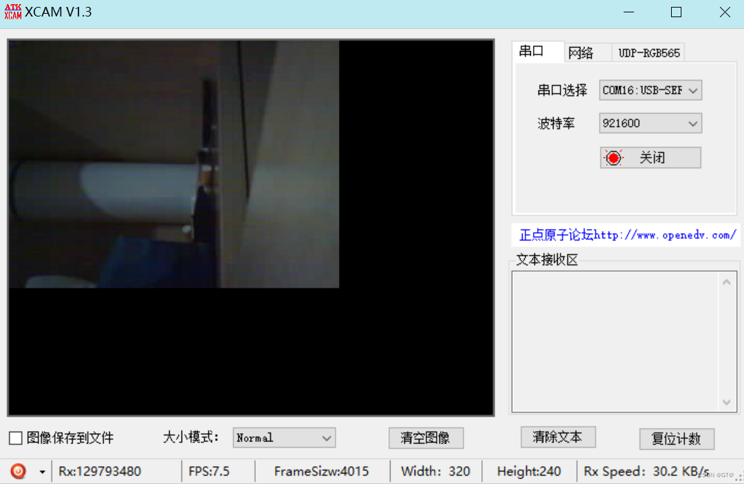
三、效果
对应串口1:
串口3


 1640
1640


 被折叠的 条评论
为什么被折叠?
被折叠的 条评论
为什么被折叠?
 到【灌水乐园】发言


