


 本文详细介绍了如何使用g2o库解决SLAM中的关键问题,包括PnP问题、ICP问题和直接法BA问题。通过定义顶点(如相机位姿和路标点)和边(表示观测误差),构建图优化模型并进行迭代优化,以求得最佳估计。具体涉及顶点和边的类定义,以及误差计算和雅克比矩阵的线性化过程。
图优化g2o的使用思路:
确定顶点,顶点就是要优化的值,需要设置更新量进行迭代
确定边,边的含义就是误差值构建,雅克比矩阵构建,设置边要连接的顶点
创建图模型、设置求解器类型
往图模型里面添加顶点和边,要设置每个顶点的ID、初始值。边需要设置连接的顶点、传入测量值、添加协方差矩阵
PnP问题
顶点是相机位姿李代数,六维。更新量为左乘李代数
边的误差值是重投影误差,即像素所在位置误差,误差维度二维
测量值就是匹配点在第二个图像的坐标位置
计算值是路标点在第二个相机下的投影
顶点vertex类
virtual void setToOriginImpl() override 设置顶点初始值
virtual void oplusImpl(const double *update) override 对顶点值进行更新
virtual bool read(istream &in) override {}
virtual bool write(ostream &out) const override {}
read 和write这两个函数通常不需要重写
class VertexPose : public g2o::BaseVertex<6, Sophus::SE3d>
{
public:
    EIGEN_MAKE_ALIGNED_OPERATOR_NEW;
    //设定被优化变量的初始值
    //override可以避免派生类中忘记重写虚函数的错误
    virtual void setToOriginImpl() override
    {
        _estimate = Sophus::SE3d();
    }

    // left multiplication on SE3
    //oplusImpl()的功能是更新,根据增量方程计算出增量之后,通过该函数对估计值进行调整,这里是左乘李代数
    //_update是李代数,H(x) * _update = b,
    virtual void oplusImpl(const double *update) override
    {
        Eigen::Matrix<double, 6, 1> update_egien;
        update_egien << update[0], update[1], update[2], update[3], update[4], update[5];
        _estimate = Sophus::SE3d::exp(update_egien) * _estimate;
    }
    //其中read(),write()函数是读盘和存盘功能,可以不进行覆写,仅仅声明一下就可以。
    virtual bool read(istream &in) override {}

    virtual bool write(ostream &out) const override {}
};
边edge类
这里是一元边,设置构造函数()构造边需要传入的参数
class EdgeProjection : public g2o::BaseUnaryEdge<2, Eigen::Vector2d, VertexPose>
2代表误差维度,这里是重投影误差,vertexpose代表需要连接的顶点类型
virtual void computeError() override 设置误差,测量值与计算值的误差
virtual void linearizeOplus() override 设置雅克比矩阵
class EdgeProjection : public g2o::BaseUnaryEdge<2, Eigen::Vector2d, VertexPose>
{
public:
    EIGEN_MAKE_ALIGNED_OPERATOR_NEW;
    EdgeProjection(const Eigen::Vector3d &pos, const Eigen::Matrix3d &K) : _pos3d(pos), _K(K) {}
    //computeError()函数是使用当前顶点的值计算的测量值与真实的测量值之间的误差
    virtual void computeError() override
    {
        const VertexPose *v = static_cast<VertexPose *> (_vertices[0]); //static_cast类型转换,将_vertices[0]类型转化为VertexPose *
        Sophus::SE3d T = v->estimate();
        Eigen::Vector3d pos_pixel = _K * (T * _pos3d);
        pos_pixel = pos_pixel / pos_pixel[2]; //转为像素坐标,消除深度
        _error = _measurement - pos_pixel.head<2>();
    }
    //linearizeOplus()函数是在当前顶点的值下,该误差对优化变量的偏导数,即计算雅可比矩阵
    virtual void linearizeOplus() override
    {
        const VertexPose *v = static_cast<VertexPose *> (_vertices[0]);
        Sophus::SE3d T = v->estimate();
        Eigen::Vector3d pos_cam = T * _pos3d; //相机坐标
        double fx = _K(0, 0);
        double fy = _K(1, 1);
        double cx = _K(0, 2);
        double cy = _K(1, 2);
        double X = pos_cam[0];
        double Y = pos_cam[1];
        double Z = pos_cam[2];
        double Z2 = pos_cam[2] * pos_cam[2];
        _jacobianOplusXi << -fx / Z, 0, fx * X / Z2, fx * X * Y / Z2, -fx - fx * X * X / Z2, fx * Y / Z,
                            0, -fy / Z, fy * Y / (Z * Z), fy + fy * Y * Y / Z2, -fy * X * Y / Z2, -fy * X / Z;
    }

    virtual bool read(istream &in) override {}
    virtual bool write(ostream &out) const override {}
private:
    Eigen::Vector3d _pos3d;
    Eigen::Matrix3d _K;
};
设置图模型
往图模型添加顶点和边。需要初始化每个顶点和边
顶点需要设置ID,设置初始值estimate,放入图优化
边需要设置ID,设置连接的顶点,设置测量值measurement,协方差矩阵(通常是单位阵),添加进图模型。
optimizer.initializeOptimization();//初始化优化器
optimizer.optimize(10); //设置迭代次数
void bundleAdjustmentG2O(const VecVector3d &points_3d, VecVector2d &points_2d, const Mat &K, Sophus::SE3d &pose)
{
    // 构建图优化,先设定g2o
    typedef g2o::BlockSolver<g2o::BlockSolverTraits<6, 3>> BlockSolverType; // BlockSolver_6_3 :表示pose 是6维,观测点是3维,用于3D SLAM中的BA。
    typedef g2o::LinearSolverDense<BlockSolverType::PoseMatrixType> LinearSolverType; //线性求解器类型
    // 梯度下降方法,可以从GN, LM, DogLeg 中选
    auto solver = new g2o::OptimizationAlgorithmGaussNewton(
        g2o::make_unique<BlockSolverType>(g2o::make_unique<LinearSolverType>()));
    g2o::SparseOptimizer optimizer; // 图模型
    optimizer.setAlgorithm(solver); // 设置求解器
    optimizer.setVerbose(true);// 打开调试输出

    // vertex
    VertexPose *vertex_pose = new VertexPose();
    vertex_pose->setId(0);
    vertex_pose->setEstimate(Sophus::SE3d());//初始化
    optimizer.addVertex(vertex_pose); //添加进图模型

    //K
    Eigen::Matrix3d K_eigen;
    K_eigen << K.at<double>(0, 0), K.at<double>(0, 1), K.at<double>(0, 2),
                K.at<double>(1, 0), K.at<double>(1, 1), K.at<double>(1, 2),
                K.at<double>(2, 0), K.at<double>(2, 1), K.at<double>(2, 2);
    //edges
    for (int i = 0; i < points_3d.size(); i++)
    {
        Eigen::Vector3d p3d = points_3d[i];
        Eigen::Vector2d p2d = points_2d[i];
        EdgeProjection *edge = new EdgeProjection(p3d,K_eigen);
        edge->setId(i);
        edge->setVertex(0,vertex_pose);//连接的点
        edge->setMeasurement(p2d);//测量值
        edge->setInformation(Eigen::Matrix2d::Identity());//初始化 协方差矩阵的逆运算
        optimizer.addEdge(edge);//把边放入优化器
    }

    chrono::steady_clock::time_point t1 = chrono::steady_clock::now();
    optimizer.initializeOptimization();//初始化优化器
    optimizer.optimize(10);//在给定图的当前配置的情况下,开始一个优化运行。和存储在类实例中的当前设置。它只能在initializeOptimization之后被调用。
ICP问题
顶点是相机位姿李代数,六维。更新量为左乘李代数
误差值是路标点三维位置误差,误差维度二维。
测量值就是深度相机的观测,像素坐标进行内参K和深度恢复的值,下面是公式,Z已知求X、Y
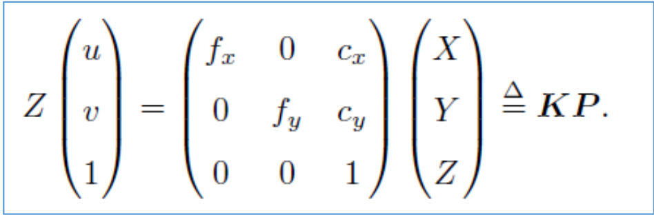
计算值是P2 = T21*P1
顶点vertex类
virtual void setToOriginImpl() override 设置顶点初始值
virtual void oplusImpl(const double *update) override 对顶点值进行更新,左乘李代数
virtual bool read(istream &in) override {}
virtual bool write(ostream &out) const override {}
read 和write这两个函数通常不需要重写
class VertexPose : public g2o::BaseVertex<6, Sophus::SE3d>
{
public:
    EIGEN_MAKE_ALIGNED_OPERATOR_NEW;
    //设定被优化变量的初始值
    //override可以避免派生类中忘记重写虚函数的错误
    virtual void setToOriginImpl() override
    {
        _estimate = Sophus::SE3d();
    }

    // left multiplication on SE3
    //oplusImpl()的功能是更新,根据增量方程计算出增量之后,通过该函数对估计值进行调整,这里是左乘李代数
    //_update是李代数,H(x) * _update = b,
    virtual void oplusImpl(const double *update) override
    {
        Eigen::Matrix<double, 6, 1> update_egien;
        update_egien << update[0], update[1], update[2], update[3], update[4], update[5];
        _estimate = Sophus::SE3d::exp(update_egien) * _estimate;
    }
    //其中read(),write()函数是读盘和存盘功能,可以不进行覆写,仅仅声明一下就可以。
    virtual bool read(istream &in) override {}

    virtual bool write(ostream &out) const override {}
};
边edge类
这里是一元边,设置构造函数()构造边需要传入的参数
class EdgeProjection : public g2o::BaseUnaryEdge<3, Eigen::Vector3d, VertexPose>
3代表误差维度,这里是三维点的误差,vertexpose代表需要连接的顶点类型
virtual void computeError() override 设置误差,测量值与计算值的误差
virtual void linearizeOplus() override 设置雅克比矩阵
class EdgeProjectionXYZ : public g2o::BaseUnaryEdge<3, Eigen::Vector3d, VertexPose>
{
public:
    EIGEN_MAKE_ALIGNED_OPERATOR_NEW;
    EdgeProjectionXYZ(const Eigen::Vector3d &pos) : _pos3d(pos) {}
    //computeError()函数是使用当前顶点的值计算的测量值与真实的测量值之间的误差
    virtual void computeError() override
    {
        const VertexPose *v = static_cast<VertexPose *> (_vertices[0]); //static_cast类型转换,将_vertices[0]类型转化为VertexPose *
        Eigen::Vector3d _pos3dcaltulate = v->estimate() * _pos3d;
        _error = _measurement - _pos3dcaltulate;
    }
    //linearizeOplus()函数是在当前顶点的值下,该误差对优化变量的偏导数,即计算雅可比矩阵
    virtual void linearizeOplus() override
    {
        const VertexPose *v = static_cast<VertexPose *> (_vertices[0]);
        Eigen::Vector3d _pos3dcaltulate = v->estimate() * _pos3d;
        _jacobianOplusXi.block<3, 3>(0, 0) = -Eigen::Matrix3d::Identity();
        _jacobianOplusXi.block<3, 3>(0, 3) = Sophus::SO3d::hat(_pos3dcaltulate);
    }

    virtual bool read(istream &in) override {}
    virtual bool write(ostream &out) const override {}
private:
    Eigen::Vector3d _pos3d;
};
设置图模型
往图模型添加顶点和边。需要初始化每个顶点和边
顶点需要设置ID,设置初始值estimate,放入图优化
边需要设置ID,设置连接的顶点,设置测量值measurement,协方差矩阵(通常是单位阵),添加进图模型。
typedef g2o::BlockSolver<g2o::BlockSolverTraits<6, 3>> BlockSolverType 6代表位姿,3代表路标点。三维slam通常这样设置
optimizer.initializeOptimization();//初始化优化器
optimizer.optimize(10); //设置迭代次数
void bundleAdjustmentG2O(const VecVector3d &points_3d1, VecVector3d &points_3d2, Sophus::SE3d &pose)
{
    // 构建图优化,先设定g2o
    typedef g2o::BlockSolver<g2o::BlockSolverTraits<6, 3>> BlockSolverType; // BlockSolver_6_3 :表示pose 是6维,观测点是3维,用于3D SLAM中的BA。
    typedef g2o::LinearSolverDense<BlockSolverType::PoseMatrixType> LinearSolverType; //线性求解器类型
    // 梯度下降方法,可以从GN, LM, DogLeg 中选
    auto solver = new g2o::OptimizationAlgorithmGaussNewton(
        g2o::make_unique<BlockSolverType>(g2o::make_unique<LinearSolverType>()));
    g2o::SparseOptimizer optimizer; // 图模型
    optimizer.setAlgorithm(solver); // 设置求解器
    optimizer.setVerbose(true);// 打开调试输出

    // vertex
    VertexPose *vertex_pose = new VertexPose();
    vertex_pose->setId(0);
    vertex_pose->setEstimate(Sophus::SE3d());//初始化
    optimizer.addVertex(vertex_pose); //添加进图模型

    //edges
    for (int i = 0; i < points_3d1.size(); i++)
    {
        Eigen::Vector3d p3d1 = points_3d1[i];
        Eigen::Vector3d p3d2 = points_3d2[i];
        EdgeProjectionXYZ *edge = new EdgeProjectionXYZ(p3d1);
        edge->setId(i);
        edge->setVertex(0,vertex_pose);//连接的点
        edge->setMeasurement(p3d2);//测量值
        edge->setInformation(Eigen::Matrix3d::Identity());//初始化 协方差矩阵的逆运算
        optimizer.addEdge(edge);//把边放入优化器
    }

    chrono::steady_clock::time_point t1 = chrono::steady_clock::now();
    optimizer.initializeOptimization();//初始化优化器
    optimizer.optimize(10);//在给定图的当前配置的情况下,开始一个优化运行。和存储在类实例中的当前设置。它只能在initializeOptimization之后被调用。
    // chrono::steady_clock::time_point t2 = chrono::steady_clock::now();
    // chrono::duration<double> time_used = chrono::duration_cast<chrono::duration<double>>(t2 - t1);
    // cout << "g2o use time:" << time_used.count() << "seconds" << endl;
    cout << "pose estimate by g2o:\n" << vertex_pose->estimate().matrix() << endl;
    pose = vertex_pose->estimate();
}
直接法BA问题
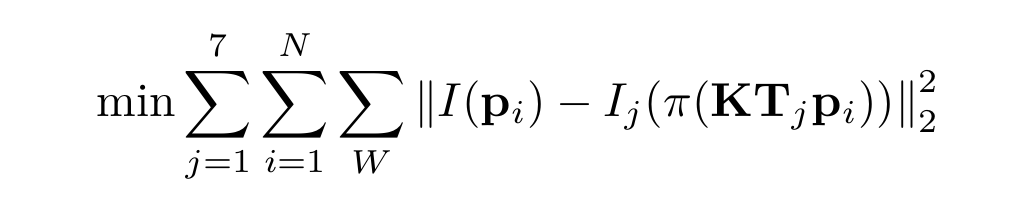
BA有两个顶点,一个是相机位姿,另一个是路标点位置。BA问题就是同时对相机位姿和路标点进行优化,每个相机位姿对一个路标点的观测就构成边。直接法的error就是像素误差,测量值是给定的,估计值(计算值)对应下式Ij的计算
相机位姿顶点是相机位姿李代数,六维。更新量为左乘李代数
路标点位姿是3维,使用G2o顶点类型g2o::VertexSBAPointXYZ
边的误差值是像素点在整个patch范围内取误差,即以当前点为中心遍历patch范围内像素误差,误差维度16维,此时patch = 4
测量值就是当前点在patch范围的像素值(真实颜色),已经给出
计算值是三维点在重投影后在当前图片的像素值
顶点VertexSophus类
对应相机位姿
virtual void setToOriginImpl() override 设置顶点初始值
virtual void oplusImpl(const double *update) override 对顶点值进行更新
virtual bool read(istream &in) override {}
virtual bool write(ostream &out) const override {}
read 和write这两个函数通常不需要重写
class VertexSophus : public g2o::BaseVertex<6, Sophus::SE3d>
{
public:
    EIGEN_MAKE_ALIGNED_OPERATOR_NEW

    VertexSophus() {}

    ~VertexSophus() {}

    bool read(std::istream &is) {}

    bool write(std::ostream &os) const {}

    virtual void setToOriginImpl()
    {
        _estimate = Sophus::SE3d(); //设置初始值
    }

    virtual void oplusImpl(const double *update_) //设置更新
    {
        Eigen::Map<const Eigen::Matrix<double, 6, 1>> update(update_);
        // setEstimate(Sophus::SE3d::exp(update) * estimate());
        _estimate = Sophus::SE3d::exp(update) * _estimate;
    }
};
边edge类
这里是二元边,设置构造函数()构造边需要传入的参数,
class EdgeDirectProjection : public g2o::BaseBinaryEdge<16, Vector16d, g2o::VertexSBAPointXYZ, VertexSophus>
16代表误差维度,patch = 4共16个误差值,g2o::VertexSBAPointXYZ, VertexSophus代表需要连接的顶点类型。g2o::VertexSBAPointXYZ是g2o内置的三维点类型,对应路标点。VertexSophus对应相机姿态李代数
virtual void computeError() override 设置误差,测量值与计算值的误差
virtual void linearizeOplus() override 设置雅克比矩阵
class EdgeDirectProjection : public g2o::BaseBinaryEdge<16, Vector16d, g2o::VertexSBAPointXYZ, VertexSophus>
{
public:
    EIGEN_MAKE_ALIGNED_OPERATOR_NEW;

    EdgeDirectProjection(float *color, cv::Mat &target)
    {
        this->origColor = color; //16个浮点数,这一点的颜色
        this->targetImg = target;
    }

    ~EdgeDirectProjection() {}

    virtual void computeError() override
    {
        // TODO START YOUR CODE HERE
        // compute projection error ...
        // 创建边要连接的顶点
        const g2o::VertexSBAPointXYZ *v_point = static_cast<g2o::VertexSBAPointXYZ *> (_vertices[0]);
        const VertexSophus *v_pose = static_cast<VertexSophus *>(_vertices[1]);
        //error
        Eigen::Vector3d point_camera = v_pose->estimate() * v_point->estimate(); //世界坐标系转相机坐标系
        Eigen::Vector3d point_camera_nor = point_camera / point_camera[2]; //归一化坐标
        Eigen::Vector2d point_piex(fx * point_camera_nor[0] + cx, fy * point_camera_nor[1] + cy); //像素坐标
        double u = point_piex[0];
        double v = point_piex[1];
        Vector16d proj;
        int patch_size = 4;
        int index = 0;
        //判断是否越界
        if (u < patch_size || u > targetImg.cols - patch_size ||
            v < patch_size || v > targetImg.rows - patch_size )
        {
            this->setLevel(1); //设置level为1,标记为outlier,下次不再对该边进行优化
            _error.setZero();
            return;
        }
        //设置误差
        for(int i = 0; i < 4; i++)
        {
            for(int j = 0; j < 4; j++)
            {
                double _px = u - 2 + i;
                double _py = v - 2 + j;
                _error[i*4+j] = origColor[i*4+j] - GetPixelValue(targetImg, _px, _py);
            }
        }
        // END YOUR CODE HERE
    }

    // Let g2o compute jacobian for you
    virtual void linearizeOplus() override
    {
        const g2o::VertexSBAPointXYZ *v_point = static_cast<g2o::VertexSBAPointXYZ *> (_vertices[0]);
        const VertexSophus *v_pose = static_cast<VertexSophus *>(_vertices[1]);
        Eigen::Vector3d point_camera = v_pose->estimate() * v_point->estimate(); //世界坐标系转相机坐标系
        Eigen::Vector3d point_camera_nor = point_camera / point_camera[2]; //归一化坐标
        Eigen::Vector2d point_piex(fx * point_camera_nor[0] + cx, fy * point_camera_nor[1] + cy); //像素坐标
        double u = point_piex[0];
        double v = point_piex[1];
        if (level() == 1)
        {
            _jacobianOplusXi = Eigen::Matrix<double, 16, 3>::Zero(); //像素误差对观测点的雅克比矩阵
            _jacobianOplusXj = Eigen::Matrix<double, 16, 6>::Zero(); //像素误差对相机位姿李代数的雅可比矩阵
            return;
        }

        Eigen::Matrix<double, 1, 2> jac_Pixel_gradient; //像素梯度
        Eigen::Matrix<double, 2, 3> jac_u_p_point; //像素坐标对camera坐标系点的求导
        Eigen::Matrix<double, 2, 6> jac_u_pose; //像素坐标对李代数的求导
        double X = point_camera[0];
        double Y = point_camera[1];
        double inv_z = 1 / point_camera[2];
        double inv_z2 = inv_z * inv_z;
        jac_u_p_point << fx*inv_z, 0, -fx*X*inv_z2,
                            0, fy*inv_z, -fy*Y*inv_z2;
        jac_u_pose << fx*inv_z, 0, -fx*X*inv_z2, -fx*X*Y*inv_z2, fx+fx*X*X*inv_z2, -fx*Y*inv_z,
                        0, fy*inv_z, -fy*Y*inv_z2, -fy-fy*Y*Y*inv_z2, fy*X*Y*inv_z2, fy*X*inv_z;

        for (int i = -2; i < 2; i++)
        {
            for (int j = -2; j < 2; j++)
            {
                int num = 4 * (i + 2) + (j + 2); //每个patch中遍历的像素点对应雅克比矩阵维度是1*3,共16个点每个patch雅克比维度16 * 3,雅克比矩阵一行对应一个像素点
                jac_Pixel_gradient << (GetPixelValue(targetImg, u+i+1, v+j) - GetPixelValue(targetImg, u+i-1, v+j)) / 2,
                                        (GetPixelValue(targetImg, u+i, v+j+1) - GetPixelValue(targetImg, u+i, v+j-1)) / 2;
                _jacobianOplusXi.block<1, 3>(num, 0) = - jac_Pixel_gradient *  jac_u_p_point * v_pose->estimate().rotationMatrix();
                _jacobianOplusXj.block<1, 6>(num, 0) = - jac_Pixel_gradient * jac_u_pose;
            }

        }
    }

    virtual bool read(istream &in) {}

    virtual bool write(ostream &out) const {}

private:
    cv::Mat targetImg;  // the target image
    float *origColor = nullptr;   // 16 floats, the color of this point
};
设置图模型
图模型设置说明同上,这里就不赘述,细节看代码注释。
添加顶点需要注意序号问题,因为要添加两种类型的顶点,先添加相机,后添加路标点。那么第一个路标点的序号就要从最后一个相机顶点序号开始。
需要注意的是,添加边时,设置边要连接的顶点序号要与边类设置的一致,否则图优化会报错。
例如:
在边类中的函数写了这两句
const g2o::VertexSBAPointXYZ *v_point = static_cast<g2o::VertexSBAPointXYZ *> (_vertices[0]);
const VertexSophus *v_pose = static_cast<VertexSophus *>(_vertices[1]);
这里0序号对应路标点顶点,1序号对应相机位姿顶点。
添加边就要注意序号!!!
edge->setVertex(1, poses_vertex[i]); //对应edge的设置
edge->setVertex(0, points_vertex[j]);
int main(int argc, char **argv)
{

    // read poses and points
    VecSE3 poses;
    VecVec3d points;
    ifstream fin(pose_file);

    while (!fin.eof())
    {
        double timestamp = 0;
        fin >> timestamp;
        if (timestamp == 0) break;
        double data[7];
        for (auto &d: data) fin >> d;
        poses.push_back(Sophus::SE3d(
                Eigen::Quaterniond(data[6], data[3], data[4], data[5]),
                Eigen::Vector3d(data[0], data[1], data[2])
        ));
        if (!fin.good()) break;
    }
    fin.close();


    vector<float *> color;
    fin.open(points_file);
    while (!fin.eof())
    {
        double xyz[3] = {0};
        for (int i = 0; i < 3; i++) fin >> xyz[i];
        if (xyz[0] == 0) break;
        points.push_back(Eigen::Vector3d(xyz[0], xyz[1], xyz[2]));
        float *c = new float[16];
        for (int i = 0; i < 16; i++) fin >> c[i];
        color.push_back(c);

        if (fin.good() == false) break;
    }
    fin.close();

    cout << "poses: " << poses.size() << ", points: " << points.size() << endl;
    for (int i = 0; i < poses.size(); i++)
    {
        cout << "before BA:\n" << "T" << i+1 << i << ":\n" << poses[i].matrix() << endl;
    }
    // read images
    vector<cv::Mat> images;
    boost::format fmt("/home/liu/slam_homework/ch7/src/%d.png");
    for (int i = 0; i < 7; i++)
    {
        images.push_back(cv::imread((fmt % i).str(), 0));
    }

    // build optimization problem
    typedef g2o::BlockSolver<g2o::BlockSolverTraits<6, 3>> DirectBlock; // BlockSolver_6_3 :表示pose 是6维,观测点是3维,用于3D SLAM中的BA。
    typedef g2o::LinearSolverDense<DirectBlock::PoseMatrixType> LinearSloverType;  //线性求解器类型
    // DirectBlock::LinearSolverType *linearSolver = new g2o::LinearSolverDense<DirectBlock::PoseMatrixType>();
    // DirectBlock *solver_ptr = new DirectBlock(linearSolver);
    // g2o::OptimizationAlgorithmLevenberg *solver = new g2o::OptimizationAlgorithmLevenberg(solver_ptr); // L-M
    auto solver = new g2o::OptimizationAlgorithmLevenberg(g2o::make_unique<DirectBlock>(g2o::make_unique<LinearSloverType>()));
    g2o::SparseOptimizer optimizer;
    optimizer.setAlgorithm(solver);
    optimizer.setVerbose(true);

    // TODO add vertices, edges into the graph optimizer
    // START YOUR CODE HERE
    vector<VertexSophus*> poses_vertex;
    vector<g2o::VertexSBAPointXYZ*> points_vertex;

    //添加相机点
    for (int i = 0; i < poses.size(); i++)
    {
        VertexSophus *v_pose = new VertexSophus();
        v_pose->setId(i);
        v_pose->setEstimate(poses[i]);
        optimizer.addVertex(v_pose);
        poses_vertex.push_back(v_pose);
    }

    //添加观测点
    for (int i = 0; i < points.size(); i++)
    {
        g2o::VertexSBAPointXYZ *v_point = new g2o::VertexSBAPointXYZ;
        v_point->setId(i + poses.size());
        v_point->setEstimate(points[i]);
        v_point->setMarginalized(true);
        optimizer.addVertex(v_point); //记得添加点
        points_vertex.push_back(v_point);
    }

    Eigen::Matrix<double,16,16> Information;
    Information.setIdentity();
    //添加边,每条边对应每个相机看到每个路标点的过程
    for (int i = 0; i < poses.size(); i++)
    {
        for (int j = 0; j < points.size(); j++)
        {
            EdgeDirectProjection *edge = new EdgeDirectProjection(color[j],images[i]);
            edge->setVertex(1, poses_vertex[i]); //对应edge的设置
            edge->setVertex(0, points_vertex[j]);
            edge->setInformation(Information); //协方差矩阵
            edge->setRobustKernel(new g2o::RobustKernelHuber()); //鲁棒核函数
            optimizer.addEdge(edge); //记得添加边
        }
    }

    // END YOUR CODE HERE

    // perform optimization
    optimizer.initializeOptimization();
    optimizer.optimize(200);

    // TODO fetch data from the optimizer
    // 从优化器中获取数据
    // START YOUR CODE HERE
    points.clear();
    poses.clear();
    for (int i = 0; i < points_vertex.size(); i++)
    {
        points.push_back(points_vertex[i]->estimate());
    }
    for (int i = 0; i < poses_vertex.size(); i++)
    {
        poses.push_back(poses_vertex[i]->estimate());
    }
    for (int i = 0; i < poses.size(); i++)
    {
        cout << "T" << i+1 << i << ":\n" << poses[i].matrix() << endl;
    }

    // END YOUR CODE HERE

    // plot the optimized points and poses
    Draw(poses, points);

    // delete color data
    for (auto &c: color) delete[] c;
    return 0;
}


 1354
1354

 被折叠的 条评论
为什么被折叠?
被折叠的 条评论
为什么被折叠?
 到【灌水乐园】发言


