


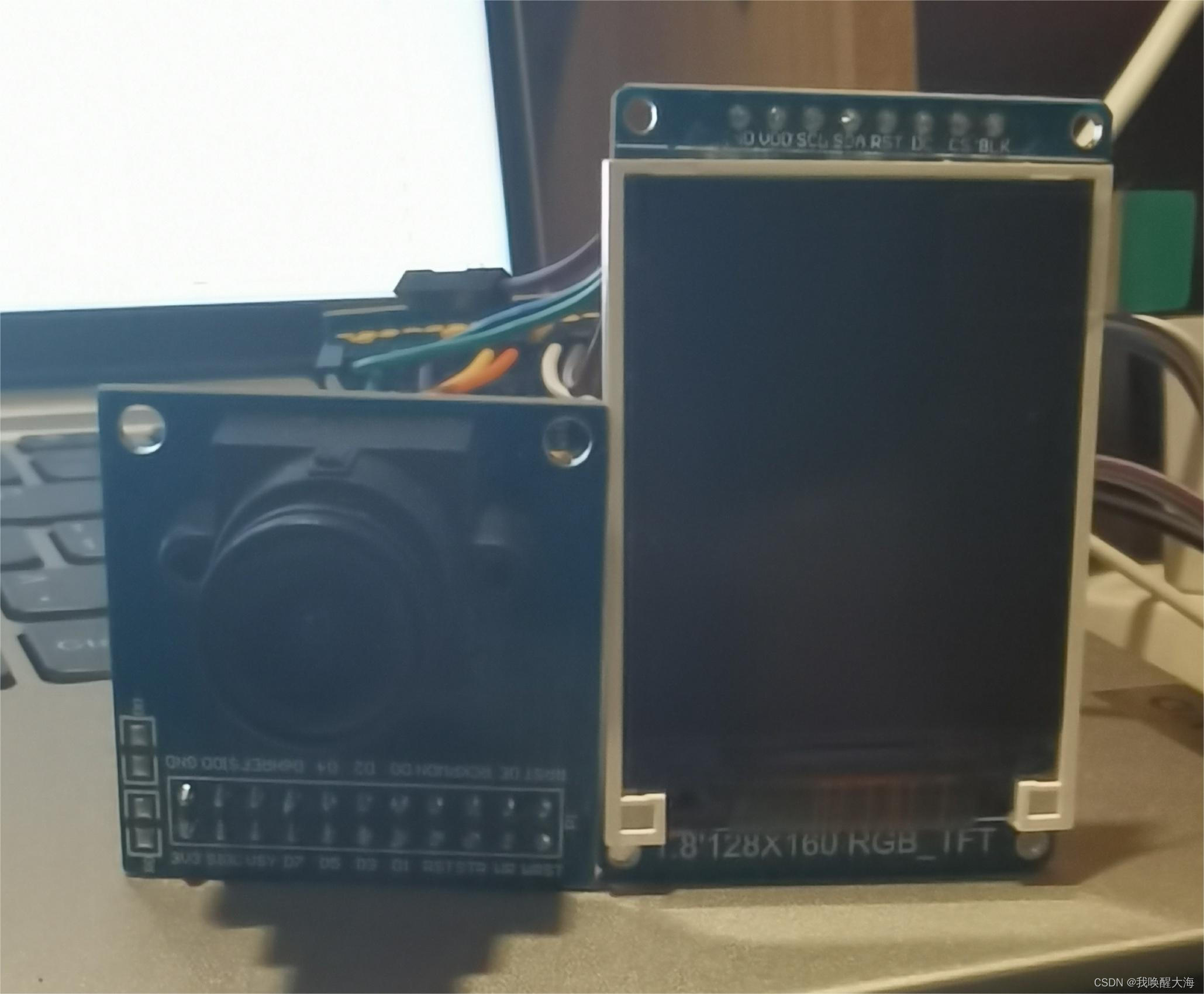
OV7670的引脚速率比STM32F103C8T6的引脚速率快很多,所以无法直接通信,需要选择带有FIFO的OV7670模块,我购买的是华强北的带FIFO OV7670模块,连同TFT屏幕连接到单片机上,如图
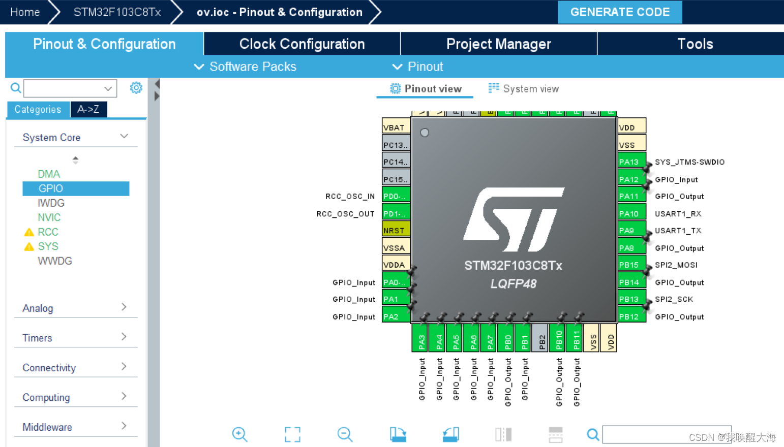
一、在cube上配置单片机引脚
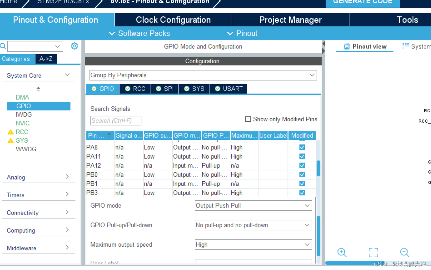
单片机连接摄像头使用了十八个引脚,所以需要配置十六个引脚。单片机和摄像头通过SCCB接口相连接,这里我使用了软件模拟SCCB的方式,十六个引脚可在单片机上自由选择,不过单片机读取摄像头的像素时需要八个相邻的引脚,我选择的是PA0-PA7,接在OV7670的D0-D7上,然后,OV7670的SCL,SDA,WRST和OE引脚,分别接在单片机的PB10,PB11,PB12和PB14引脚,OV7670的WR,RRST,RCLK和VS引脚,接在单片机的PA8,PB0,PA11和PA12引脚,如图
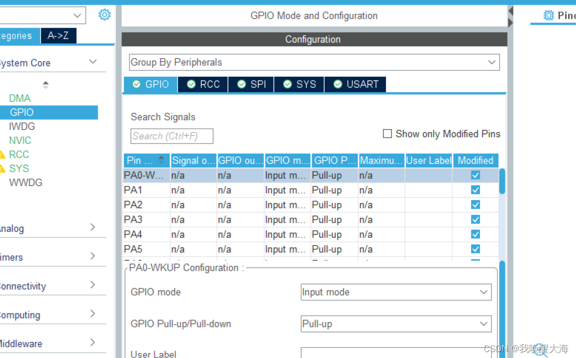
其中,PA0-PA7配置为上拉输入模式,如图
PB10,PB11,PB12和PB14引脚配置为输出模式,引脚速率一定设置为高速,如图
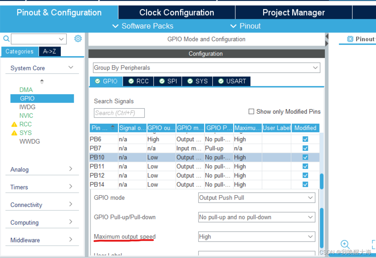
PA8,PB0和PA11引脚配置为输出模式,速率为高速,PA12引脚配置为上拉输入模式,如图
至此引脚就配置好了,生成keil工程。
二、在keil中编写程序
1.模拟SCCB接口
单片机和OV7670的通信通过SCCB接口,也就是PB10和PB11所连接的SCL、SDA引脚,设计到数据的收和发,所以PB11引脚的模式需要在使用过程中变换,分别是上拉输入和输出模式,代码如下
void SCCB_SDA_IN(void)//配置PB11引脚的工作模式
{

        GPIO_InitTypeDef GPIO_InitStruct = {0};
		GPIO_InitStruct.Pin = GPIO_PIN_11;
        GPIO_InitStruct.Mode = GPIO_MODE_INPUT;
		GPIO_InitStruct.Speed = GPIO_SPEED_FREQ_HIGH;
		GPIO_InitStruct.Pull = GPIO_PULLUP;
        HAL_GPIO_Init(GPIOB, &GPIO_InitStruct);
}
void SCCB_SDA_OUT(void)
{

        GPIO_InitTypeDef GPIO_InitStruct = {0};
		GPIO_InitStruct.Pin = GPIO_PIN_11;
		GPIO_InitStruct.Mode = GPIO_MODE_OUTPUT_PP;
		GPIO_InitStruct.Pull = GPIO_NOPULL;
		GPIO_InitStruct.Speed = GPIO_SPEED_FREQ_HIGH;
		HAL_GPIO_Init(GPIOB, &GPIO_InitStruct);
        HAL_GPIO_WritePin(GPIOB,GPIO_PIN_11,1);
}
下面是SCCB接口在软件模拟时用到的基础函数,需要注意的是微秒级的延时,写成毫秒是会出错的。
void SCCB_Start(void)
{

		SCCB_SDA_OUT();
        SCCB_W_SDA(1);
        SCCB_W_SCL(1);
        Delay_us(50);
        SCCB_W_SDA(0);
        Delay_us(50);
        SCCB_W_SCL(0);
		Delay_us(50);
}

void SCCB_Stop(void)
{
		SCCB_SDA_OUT();
		SCCB_W_SDA(0);
		Delay_us(50);
		SCCB_W_SCL(1);
		Delay_us(50);
		SCCB_W_SDA(1);
		Delay_us(50);
}


uint8_t SCCB_SendByte(uint8_t Byte)
{
    uint8_t i,res = 0;

     SCCB_SDA_OUT();
    for (i = 0; i < 8; i ++)
    {
			if((Byte << i) & 0x80)
			{
				SCCB_W_SDA(1);
			}
			else
			{
				SCCB_W_SDA(0);
			}
        Delay_us(50);

        SCCB_W_SCL(1);
        Delay_us(50);
        SCCB_W_SCL(0);

    }
		SCCB_SDA_IN();
		Delay_us(50);
		SCCB_W_SCL(1);
		Delay_us(50);
		if(SCCB_R_SDA())res = 1;
		else res = 0;
		SCCB_W_SCL(0);
		return res;

}

uint8_t SCCB_ReceiveByte(void)
{

    uint8_t i, Byte = 0x00;
    SCCB_SDA_IN();

    for (i = 0; i < 8; i ++)
    {
		Delay_us(50);
        SCCB_W_SCL(1);

		Byte = Byte << 1;
        if (SCCB_R_SDA()){Byte ++;}
		Delay_us(50);
        SCCB_W_SCL(0);

    }
    return Byte;
}

void SCCB_SendNA()
{
		SCCB_SDA_OUT();
		Delay_us(50);
		SCCB_W_SDA(1);
		SCCB_W_SCL(1);
		Delay_us(50);
		SCCB_W_SCL(0);
		Delay_us(50);
		SCCB_W_SDA(0);
		Delay_us(50);
}

uint8_t SCCB_ReceiveAck(void)
{
        uint8_t AckBit;
        SCCB_SDA_IN();
	    SCCB_W_SCL(0);
		Delay_us(100);
        SCCB_W_SCL(1);
		Delay_us(100);
        AckBit = SCCB_R_SDA();
        SCCB_W_SCL(0);
		Delay_us(100);
        SCCB_SDA_OUT();

        return AckBit;
}
我所用的微秒级延时函数如下
#define 		AHB_freq			72000000UL


void Delay_us(uint32_t us)
{
	us = (1<<25) <= us ? (1<<25) - 1 : us;

	SysTick->LOAD = us * (AHB_freq / 8000000);
	SysTick->VAL = 0;
	SysTick->CTRL = 0x01;
	while(!(SysTick->CTRL & SysTick_CTRL_COUNTFLAG_Msk));
	SysTick->CTRL &= ~(0x01<<SysTick_CTRL_ENABLE_Pos);

}
2.通过模拟的SCCB接口和OV7670通信,并初始化OV7670的寄存器
首先是对OV7670寄存器的读写操作函数
uint8_t OV7670_WriteReg(uint8_t RegAddress, uint8_t Data)//可写为void类型
{
	uint8_t res=0;
    SCCB_Start();

    if(SCCB_SendByte(0X42))res = 1;
    Delay_us(100);

    if(SCCB_SendByte(RegAddress))res = 1;
    Delay_us(100);

    if(SCCB_SendByte(Data)) res = 1;
    Delay_us(100);

    SCCB_Stop();
	return res;
}

uint8_t OV7670_ReadReg(uint8_t RegAddress)
{
    uint8_t Data,a = 0;

    SCCB_Start();
	SCCB_SendByte(0x42);
    Delay_us(100);
    SCCB_SendByte(RegAddress);
    Delay_us(100);
    SCCB_Stop();
    Delay_us(100);
    SCCB_Start();
    SCCB_SendByte(0x43);
	Delay_us(100);
    Data = SCCB_ReceiveByte();

    SCCB_SendNA();
    SCCB_Stop();

    return Data;
}
我记得当时可以直接读取OV7670的0X0A、0X0B寄存器,这是它的ID号,读出来的结果是0X76、0X73,可以通过这两个数据判断模拟SCCB接口的函数写的是否正确,调用上面的OV7670_ReadReg函数,大概长这样
void transmit(uint8_t a)//发送到串口显示
{

	HAL_UART_Transmit(&huart1,&a,1,5);
}


    uint8_t ac=0;

    ac = OV7670_ReadReg(0x0a);//写在主函数里
	transmit(ac);

    ac = OV7670_ReadReg(0x0b);
    transmit(ac);
如果串口收到的数据是76和73,代表可以通信了,下面开始配置OV7670的寄存器,寄存器初始化的数据是可变的,不是一个固定的数组,在配置的有错误时,会出现花屏的现象,以下是我用的初始数组和配置函数,设置图片清晰度的函数是我在网上找的
const  uint8_t OV7670_Reg[166][2]=
{

    {0x3a, 0x04},
    {0x40, 0x10},
    {0x12, 0x14},
    {0x32, 0x80},
    {0x17, 0x17},
    {0x18, 0x05},
    {0x19, 0x02},
    {0x1a, 0x7b},//0x7a,
    {0x03, 0x0a},//0x0a,
    {0x0c, 0x0c},
    {0x3e, 0x00},
    {0x70, 0x00},
    {0x71, 0x01},
    {0x72, 0x11},
    {0x73, 0x09},
    {0xa2, 0x02},
    {0x11, 0x00},
    {0x7a, 0x20},
    {0x7b, 0x1c},
    {0x7c, 0x28},
    {0x7d, 0x3c},
    {0x7e, 0x55},
    {0x7f, 0x68},
    {0x80, 0x76},
    {0x81, 0x80},
    {0x82, 0x88},
    {0x83, 0x8f},
    {0x84, 0x96},
    {0x85, 0xa3},
    {0x86, 0xaf},
    {0x87, 0xc4},
    {0x88, 0xd7},
    {0x89, 0xe8},
    {0x13, 0xe0},
    {0x00, 0x00},
    {0x10, 0x00},
    {0x0d, 0x00},//窗口
    {0x14, 0x38},
    {0xa5, 0x05},
    {0xab, 0x07},
    {0x24, 0x75},
    {0x25, 0x63},
    {0x26, 0xA5},
    {0x9f, 0x78},
    {0xa0, 0x68},
    {0xa1, 0x03},//0x0b,
    {0xa6, 0xdf},//0xd8,
    {0xa7, 0xdf},//0xd8,
    {0xa8, 0xf0},
    {0xa9, 0x90},
    {0xaa, 0x94},
    {0x13, 0xe5},
    {0x0e, 0x61},
    {0x0f, 0x4b},
    {0x16, 0x02},
    {0x1e, 0x07},//0x07,0x27
    {0x21, 0x02},
    {0x22, 0x91},
    {0x29, 0x07},
    {0x33, 0x0b},
    {0x35, 0x0b},
    {0x37, 0x1d},
    {0x38, 0x71},
    {0x39, 0x2a},
    {0x3c, 0x78},
    {0x4d, 0x40},
    {0x4e, 0x20},
    {0x69, 0x5d},
    {0x6b, 0x40},//PLL
    {0x74, 0x19},
    {0x8d, 0x4f},
    {0x8e, 0x00},
    {0x8f, 0x00},
    {0x90, 0x00},
    {0x91, 0x00},
    {0x92, 0x00},//0x19,//0x66
    {0x96, 0x00},
    {0x9a, 0x80},
    {0xb0, 0x84},
    {0xb1, 0x0c},
    {0xb2, 0x0e},
    {0xb3, 0x82},
    {0xb8, 0x0a},
    {0x43, 0x14},
    {0x44, 0xf0},
    {0x45, 0x34},
    {0x46, 0x58},
    {0x47, 0x28},
    {0x48, 0x3a},
    {0x59, 0x88},
    {0x5a, 0x88},
    {0x5b, 0x44},
    {0x5c, 0x67},
    {0x5d, 0x49},
    {0x5e, 0x0e},
    {0x64, 0x04},
    {0x65, 0x20},
    {0x66, 0x05},
    {0x94, 0x04},
    {0x95, 0x08},
    {0x6c, 0x0a},
    {0x6d, 0x55},
    {0x6e, 0x11},
    {0x6f, 0x9f},
    {0x6a, 0x40},

    {0x13, 0xe7},
    {0x15, 0x00},
    {0x4f, 0x80},
    {0x50, 0x80},
    {0x51, 0x00},
    {0x52, 0x22},
    {0x53, 0x5e},
    {0x54, 0x80},
    {0x55, 0x00},
    {0x56, 0x60},
    {0x57, 0x90},
    {0x58, 0x9e},
    {0x41, 0x08},
    {0x3f, 0x05},
    {0x75, 0x05},
    {0x76, 0xe1},
    {0x4c, 0x0F},
    {0x77, 0x0a},
    {0x3d, 0xc2},    //0xc0,
    {0x4b, 0x09},
    {0xc9, 0xc8},
    {0x41, 0x38},

    {0x34, 0x11},
    {0x3b, 0x02},//0x00,//0x02,
    {0xa4, 0x89},//0x88,
    {0x96, 0x00},
    {0x97, 0x30},
    {0x98, 0x20},
    {0x99, 0x30},
    {0x9a, 0x84},
    {0x9b, 0x29},
    {0x9c, 0x03},
    {0x9d, 0x4c},
    {0x9e, 0x3f},
    {0x78, 0x04},
    {0x79, 0x01},
    {0xc8, 0xf0},
    {0x79, 0x0f},
    {0xc8, 0x00},
    {0x79, 0x10},
    {0xc8, 0x7e},
    {0x79, 0x0a},
    {0xc8, 0x80},
    {0x79, 0x0b},
    {0xc8, 0x01},
    {0x79, 0x0c},
    {0xc8, 0x0f},
    {0x79, 0x0d},
    {0xc8, 0x20},
    {0x79, 0x09},
    {0xc8, 0x80},
    {0x79, 0x02},
    {0xc8, 0xc0},
    {0x79, 0x03},
    {0xc8, 0x40},
    {0x79, 0x05},
    {0xc8, 0x30},
    {0x69, 0xaa},
    {0x09, 0x00},
    {0x3b, 0x42},
    {0x2d, 0x01}
};


void OV7670_config_window(unsigned int startx,unsigned int starty,unsigned int width, unsigned int height)
{
	unsigned int endx;
	unsigned int endy;
	unsigned char temp_reg1, temp_reg2;
	unsigned char temp=0;

	endx=(startx+width*2)%784;
	endy=(starty+height+height);
  temp_reg1 = OV7670_ReadReg(0x03);
	temp_reg1 &= 0xf0;
	temp_reg2 = OV7670_ReadReg(0x32);
	temp_reg2 &= 0xc0;

	// Horizontal
	temp = temp_reg2|((endx&0x7)<<3)|(startx&0x7);
	OV7670_WriteReg(0x32, temp );
	temp = (startx&0x7F8)>>3;
	OV7670_WriteReg(0x17, temp );
	temp = (endx&0x7F8)>>3;
	OV7670_WriteReg(0x18, temp );

	// Vertical
	temp =temp_reg1|((endy&0x3)<<2)|(starty&0x3);
	OV7670_WriteReg(0x03, temp );
	temp = (starty & 0x3fc)>>2;
	OV7670_WriteReg(0x19, temp );
	temp = (endy & 0x3fc)>>2;
	OV7670_WriteReg(0x1A, temp );
}


void OV7670_Configure(void)
{
	uint8_t i;
	OV7670_WriteReg(0x12,0x80);
	Delay_us(100000);


	for(i=0;i<166;i++)
	{
	   	OV7670_WriteReg(OV7670_Reg[i][0],OV7670_Reg[i][1]);
    }


	OV7670_config_window(184,10,128,160);//配置OV7670输出图片的清晰度为128*160
	//OV7670_config_window(184,10,80,160);

}
然后是对除SDA、SCL引脚外的六个引脚的读取或赋值函数
uint8_t OV7670_VS(void)
{
    return HAL_GPIO_ReadPin(GPIOA,GPIO_PIN_12);
}

void OV7670_W_RRST(uint8_t BitValue)
{
    HAL_GPIO_WritePin(GPIOB, GPIO_PIN_0, BitValue);
    Delay_us(10);
}

void OV7670_W_WRST(uint8_t BitValue)
{
    HAL_GPIO_WritePin(GPIOB, GPIO_PIN_12, BitValue);
    Delay_us(10);
}
void OV7670_W_WEN(uint8_t BitValue)
{
    HAL_GPIO_WritePin(GPIOA, GPIO_PIN_8, BitValue);
    Delay_us(10);
}
void OV7670_W_OE(uint8_t BitValue)
{
    HAL_GPIO_WritePin(GPIOB, GPIO_PIN_14, BitValue);
    Delay_us(10);
}
void OV7670_W_RCLK(uint8_t BitValue)
{
    HAL_GPIO_WritePin(GPIOA, GPIO_PIN_11, BitValue);
    Delay_us(10);
}
3.将OV7670的图片读取并显示在1.8寸TFT屏幕上
如果对OV7670寄存器的配置基本正确的话,可以开始显示图片了,首先可以配置寄存器0X70、0X71为0X3A、0XB5,让OV7670输出八色彩条,检查图片颜色的对错,具体为
    uint8_t value1 = 0,value2 = 0;
    uint16_t w,h,color;


void ov7670()//单片机读取OV7670的图片像素并发送到TFT屏幕上
{
	while(OV7670_VS()==0){};
		OV7670_W_WRST(0);
        OV7670_W_WRST(1);
        OV7670_W_WEN(1);
		Delay_us(40000);
		while(OV7670_VS()==0);
		OV7670_W_WRST(0);
        OV7670_W_WRST(1);
        OV7670_W_WEN(0);
		Delay_us(50000);

		OV7670_W_OE(0);
		OV7670_W_RRST(0);

		OV7670_W_RCLK(0);
		Delay_us(20000);
		OV7670_W_RCLK(1);
		Delay_us(20000);
		OV7670_W_RCLK(0);
		Delay_us(20000);
        OV7670_W_RRST(1);
		Delay_us(20000);
		OV7670_W_RCLK(1);


		set_windows(0,0,lcddev.width-1,lcddev.height-1);
		for(h=0;h<160;h++)//128
		{
			for(w=0;w<128;w++)
			{
				OV7670_W_RCLK(0);
				value1 = (uint8_t)GPIOA->IDR & 0xff;
				OV7670_W_RCLK(1);
				OV7670_W_RCLK(0);
				value2 = (uint8_t)GPIOA->IDR & 0xff;
				OV7670_W_RCLK(1);
				color = (value1 << 8) | value2;
				TFT_WRITE_u16_DATA(color);
			}

		}
		OV7670_W_OE(1);
}


//写在主函数里
    OV7670_WriteReg(0x70, 0x3A);//输出八色彩条,不调用则输出摄像头拍摄到的图像
    OV7670_WriteReg(0x71, 0xB5);


    tft_init();
    lcd_clear((uint16_t)WHITE);
    while(1)
    {
        Delay_us(1000000);
        ov7670();
    }
如果在屏幕上看到了八色彩条,可以注释掉对0X70、0X71寄存器配置的函数,之后可以看到摄像头拍摄到的图像。


 3984
3984

 被折叠的 条评论
为什么被折叠?
被折叠的 条评论
为什么被折叠?
 到【灌水乐园】发言


