


接上篇博客:Quartus和ModelSim软件的使用(3-8译码器)-CSDN博客
一、全加器的定义
全加器是一种数字电路组件,用于将两个二进制数的每一位和一个进位位相加。全加器与半加器不同,它可以处理三个输入:两个待加的二进制位和来自前一位的进位。全加器的输出包括一个和位(Sum)和一个进位位(Cout)。
一位全加器的运算法则如下:
1、输入:
A(加数的一位)
B(被加数的一位)
Cin(前一位的进位)
2、输出:
Sum(和位):A、B和Cin的异或结果,表示该位的二进制和。
Cout(进位输出):A、B和Cin的任意两个或三个的与运算结果,表示该位的进位。
二、电路图(一位全加器)
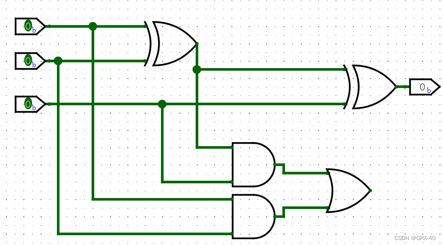
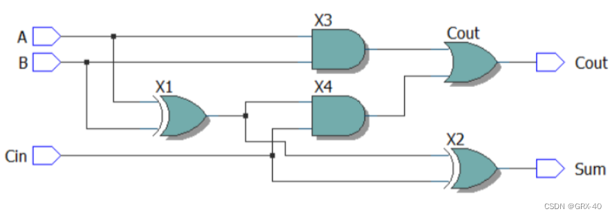
三、生成RTL
代码:
module FullAdder1Bit (

  input A, B, Cin,

  output Sum, Cout

);


  wire X1, X2, X3, X4;

  // 异或门

  assign X1 = A ^ B;

  assign X2 = X1 ^ Cin;

  // 与门

  assign X3 = A & B;

  assign X4 = X1 & Cin;

  // 或门

  assign Cout = X3 | X4;

  assign Sum = X2;


endmodule
电路图:
四、四位全加器
经过上面对全加器的了解,下面我们通过上述原理实现四位全加器 。
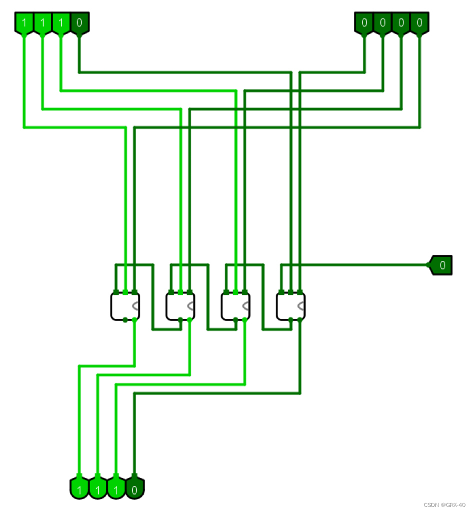
代码以及生成图:
module FourBitAdder(
  input [3:0] A,
  input [3:0] B,
  input Cin,
  output [3:0] Sum,
  output Cout
);

  wire [3:0] carry_out_intermediate;
  wire [3:0] sum_intermediate;

  FullAdder1Bit fa0 (.A(A[0]), .B(B[0]), .Cin(Cin), .Sum(sum_intermediate[0]), .Cout(carry_out_intermediate[0]));
  FullAdder1Bit fa1 (.A(A[1]), .B(B[1]), .Cin(carry_out_intermediate[0]), .Sum(sum_intermediate[1]), .Cout(carry_out_intermediate[1]));
  FullAdder1Bit fa2 (.A(A[2]), .B(B[2]), .Cin(carry_out_intermediate[1]), .Sum(sum_intermediate[2]), .Cout(carry_out_intermediate[2]));
  FullAdder1Bit fa3 (.A(A[3]), .B(B[3]), .Cin(carry_out_intermediate[2]), .Sum(sum_intermediate[3]), .Cout(carry_out_intermediate[3]));

  assign Sum = sum_intermediate;
  assign Cout = carry_out_intermediate[3];

endmodule

module FullAdder1Bit(
  input A,
  input B,
  input Cin,
  output Sum,
  output Cout
);

  assign Sum = A ^ B ^ Cin;
  assign Cout = (A & B) | (B & Cin) | (A & Cin);

endmodule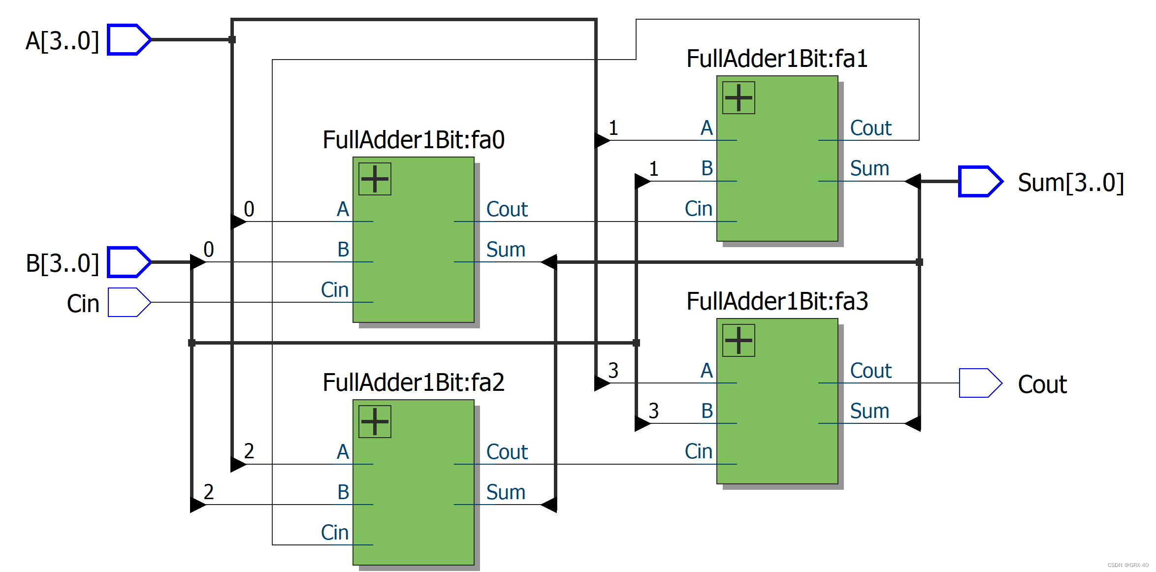
附
16位ALU的电路设计:
代码:
module SimpleALU_16bit (
    input wire [15:0] A,
    input wire [15:0] B,
    input wire [3:0]  opcode,
    output reg [15:0] result,
    output reg zero,
    output reg overflow,
    output reg carry
);

always @(A or B or opcode) begin
    case(opcode)
        4'b0000: // Addition
            begin
                result = A + B;
                zero = (result == 16'b0);
                overflow = (A[15] & B[15] & ~result[15]) | (~A[15] & ~B[15] & result[15]);
                carry = (A[15] & B[15]) | (~result[15] & (A[15] | B[15]));
            end
        4'b0001: // Subtraction
            begin
                result = A - B;
                zero = (result == 16'b0);
                overflow = (A[15] & ~B[15] & ~result[15]) | (~A[15] & B[15] & result[15]);
                carry = (A[15] | ~B[15]) & (~result[15] | (A[15] & ~B[15]));
            end
        4'b0010: // AND
            begin
                result = A & B;
                zero = (result == 16'b0);
                overflow = 1'b0;
                carry = 1'b0;
            end
        4'b0011: // OR
            begin
                result = A | B;
                zero = (result == 16'b0);
                overflow = 1'b0;
                carry = 1'b0;
            end
        4'b0100: // XOR
            begin
                result = A ^ B;
                zero = (result == 16'b0);
                overflow = 1'b0;
                carry = 1'b0;
            end
        // Add more operations as needed
        // ...

        default:
            begin
                result = 16'b0;
                zero = 1'b0;
                overflow = 1'b0;
                carry = 1'b0;
            end
    endcase
end

endmodule
由于电路图过于复杂,字体较小,不便于观看,便省略
测试代码:
// Copyright (C) 1991-2013 Altera Corporation
// Your use of Altera Corporation's design tools, logic functions
// and other software and tools, and its AMPP partner logic
// functions, and any output files from any of the foregoing
// (including device programming or simulation files), and any
// associated documentation or information are expressly subject
// to the terms and conditions of the Altera Program License
// Subscription Agreement, Altera MegaCore Function License
// Agreement, or other applicable license agreement, including,
// without limitation, that your use is for the sole purpose of
// programming logic devices manufactured by Altera and sold by
// Altera or its authorized distributors.  Please refer to the
// applicable agreement for further details.
// *****************************************************************************
// This file contains a Verilog test bench template that is freely editable to
// suit user's needs .Comments are provided in each section to help the user
// fill out necessary details.
// *****************************************************************************
// Generated on "12/17/2023 21:05:17"

// Verilog Test Bench template for design : SimpleALU_16bit
//
// Simulation tool : ModelSim (Verilog)
//

`timescale 1 ps/ 1 ps
module SimpleALU_16bit_vlg_tst();
// constants
// general purpose registers
reg eachvec;
// test vector input registers
reg [15:0] A;
reg [15:0] B;
reg [3:0] opcode;
// wires
wire carry;
wire overflow;
wire [15:0]  result;
wire zero;

// assign statements (if any)
SimpleALU_16bit i1 (
// port map - connection between master ports and signals/registers
	.A(A),
	.B(B),
	.carry(carry),
	.opcode(opcode),
	.overflow(overflow),
	.result(result),
	.zero(zero)
);
initial begin
    $display("Starting 16-bit ALU Testbench");

    // Test Case 1: Addition
    A = 16'h1234;
    B = 16'h5678;
    opcode = 4'b0000; // Addition
    #10; // Wait for some time
    $display("Test Case 1 - Addition: Result = %h, Zero = %b, Carry = %b, Overflow = %b", result, zero, carry, overflow);
    // Test Case 2: Subtraction
    A = 16'hABCD;
    B = 16'h5432;
    opcode = 4'b0001; // Subtraction
    #10; // Wait for some time
    $display("Test Case 2 - Subtraction: Result = %h, Zero = %b, Carry = %b, Overflow = %b", result, zero, carry, overflow);

    // Add more test cases for other operations


  end

endmodule


 2484
2484


 被折叠的 条评论
为什么被折叠?
被折叠的 条评论
为什么被折叠?
 到【灌水乐园】发言


