


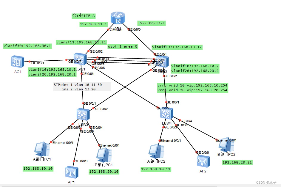
实验拓扑:
1. 链路聚合配置:
要求:SW1 和 SW2 分别通过 GE0/0/3,GE0/0/4 和 GE0/0/5 接口相互连接, 把这三个接口捆绑成一个逻辑接口,使用的模式为 static-lacp。 SW2 为主动端,两台设备之间最大可用的带宽为 2G。
操作:在LSW1和LSW2上都配置如下命令。
interface Eth-Trunk1
 port link-type trunk
 port trunk allow-pass vlan 2 to 4094
 mode lacp-static
 max active-linknumber 2
trunkport GigabitEthernet 0/0/3 0/0/4 0/0/5| 命令 | 作用 |
|---|---|
| interface Eth-Trunk1 | 进入以太网聚合接口配置模式 |
| port link-type trunk | 配置接口为聚合接口,并且设置链路类型为 Trunk |
| port trunk allow-pass vlan 2 to 4094 | 设置该聚合接口允许通过的 VLAN 范围为从 VLAN 2 到 VLAN 4094 |
| mode lacp-static | 将聚合接口的工作模式设置为静态 LACP 模式 |
| max active-linknumber 2 | 设置该聚合接口最大的主动链路数为 2 条,这样两台设备之间最大可用的带宽为 2G。 |
2. VLAN 配置:
要求:在每台交换机创建 VLAN,VLAN ID 分别为 10、11、13、20、30 将 VLAN 划分相应的接口,部门 A---vlan10,部门 B---vlan20, LSW1 G0/0/2---vlan11,LSW2 G0/0/1---vlan13
3. Trunk 配置:
要求:所有交换机互连接口划分配置为 trunk 接口,只允许 VLAN1、10、11、13、20、30 的 VLAN 通过;
2&3的操作:
LSW1
vlan batch 10 11 13 20 30
interface GigabitEthernet0/0/1
 port link-type trunk
 port trunk allow-pass vlan 10 to 11 13 20 30
interface GigabitEthernet0/0/2
 port link-type trunk
 port trunk pvid vlan 11
 port trunk allow-pass vlan 10 to 11 13 20 30
interface GigabitEthernet0/0/6
 port link-type trunk
 port trunk allow-pass vlan 10 to 11 13 20 30
interface GigabitEthernet0/0/7
 port link-type trunk
 port trunk allow-pass vlan 10 to 11 13 20 30
interface Vlanif11
ip address 192.168.11.11 255.255.255.0| 命令 | 作用 |
|---|---|
| vlan batch 10 11 13 20 30 | 创建并配置 VLAN,将 VLAN ID 为 10、11、13、20 和 30 的 VLAN 添加到 VLAN 数据库中 |
| interface GigabitEthernet0/0/1 | 进入 GigabitEthernet0/0/1 接口的配置模式 |
| port link-type trunk | 配置接口为聚合接口,并且设置链路类型为 Trunk |
| port trunk allow-pass vlan 10 to 11 13 20 30 | 设置该聚合接口允许通过的 VLAN 范围为 VLAN 10、11、13、20 和 30 |
| interface GigabitEthernet0/0/2 | 进入 GigabitEthernet0/0/2 接口的配置模式 |
| port link-type trunk | 配置接口为聚合接口,并且设置链路类型为 Trunk |
| port trunk pvid vlan 11 | 设置该聚合接口的 PVID 为 11 |
| port trunk allow-pass vlan 10 to 11 13 20 30 | 设置该聚合接口允许通过的 VLAN 范围为 VLAN 10、11、13、20 和 30 |
| interface GigabitEthernet0/0/6 | 进入 GigabitEthernet0/0/6 接口的配置模式 |
| port link-type trunk | 配置接口为聚合接口,并且设置链路类型为 Trunk |
| port trunk allow-pass vlan 10 to 11 13 20 30 | 设置该聚合接口允许通过的 VLAN 范围为 VLAN 10、11、13、20 和 30 |
| interface GigabitEthernet0/0/7 | 进入 GigabitEthernet0/0/7 接口的配置模式 |
| port link-type trunk | 配置接口为聚合接口,并且设置链路类型为 Trunk |
| port trunk allow-pass vlan 10 to 11 13 20 30 | 设置该聚合接口允许通过的 VLAN 范围为 VLAN 10、11、13、20 和 30 |
| interface Vlanif11 | 进入 VLAN 11 的虚拟接口配置模式 |
| ip address 192.168.11.11 255.255.255.0 | 为 VLAN 11 虚拟接口配置 IP 地址 192.168.11.11 和子网掩码 255.255.255.0 |
LSW2
vlan batch 10 to 11 13 20 30
interface GigabitEthernet0/0/1
 port link-type trunk
 port trunk pvid vlan 13
 port trunk allow-pass vlan 10 to 11 13 20 30
interface GigabitEthernet0/0/2
 port link-type trunk
 port trunk allow-pass vlan 10 to 11 13 20 30
interface GigabitEthernet0/0/6
 port link-type trunk
 port trunk allow-pass vlan 10 to 11 13 20 30
interface Vlanif13
ip address 192.168.13.12 255.255.255.0| 命令 | 作用 |
|---|---|
| vlan batch 10 to 11 13 20 30 | 创建并配置 VLAN,将 VLAN ID 为 10 到 11、13、20 和 30 的 VLAN 添加到 VLAN 数据库中 |
| interface GigabitEthernet0/0/1 | 进入 GigabitEthernet0/0/1 接口的配置模式 |
| port link-type trunk | 配置接口为聚合接口,并且设置链路类型为 Trunk |
| port trunk pvid vlan 13 | 设置该聚合接口的 PVID 为 13 |
| port trunk allow-pass vlan 10 to 11 13 20 30 | 设置该聚合接口允许通过的 VLAN 范围为 VLAN 10、11、13、20 和 30 |
| interface GigabitEthernet0/0/2 | 进入 GigabitEthernet0/0/2 接口的配置模式 |
| port link-type trunk | 配置接口为聚合接口,并且设置链路类型为 Trunk |
| port trunk allow-pass vlan 10 to 11 13 20 30 | 设置该聚合接口允许通过的 VLAN 范围为 VLAN 10、11、13、20 和 30 |
| interface GigabitEthernet0/0/6 | 进入 GigabitEthernet0/0/6 接口的配置模式 |
| port link-type trunk | 配置接口为聚合接口,并且设置链路类型为 Trunk |
| port trunk allow-pass vlan 10 to 11 13 20 30 | 设置该聚合接口允许通过的 VLAN 范围为 VLAN 10、11、13、20 和 30 |
| interface Vlanif13 | 进入 VLAN 13 的虚拟接口配置模式 |
| ip address 192.168.13.12 255.255.255.0 | 为 VLAN 13 虚拟接口配置 IP 地址 192.168.13.12 和子网掩码 255.255.255.0 |
LSW3&LSW4
vlan batch 10 to 11 13 20 30
interface GigabitEthernet0/0/1
 port link-type trunk
 port trunk allow-pass vlan 10 to 11 13 20 30
interface GigabitEthernet0/0/2
 port link-type trunk
 port trunk allow-pass vlan 10 to 11 13 20 30
interface GigabitEthernet0/0/3
 port link-type access
 port default vlan 10
 interface GigabitEthernet0/0/4
 port link-type access
 port default vlan 20
 interface GigabitEthernet0/0/5
 port link-type trunk
 port trunk pvid vlan 30
port trunk allow-pass vlan 10 to 11 13 20 30| 命令 | 作用 |
|---|---|
| vlan batch 10 to 11 13 20 30 | 创建并配置 VLAN,将 VLAN ID 为 10 到 11、13、20 和 30 的 VLAN 添加到 VLAN 数据库中 |
| interface GigabitEthernet0/0/1 | 进入 GigabitEthernet0/0/1 接口的配置模式 |
| port link-type trunk | 配置接口为聚合接口,并且设置链路类型为 Trunk |
| port trunk allow-pass vlan 10 to 11 13 20 30 | 设置该聚合接口允许通过的 VLAN 范围为 VLAN 10、11、13、20 和 30 |
| interface GigabitEthernet0/0/2 | 进入 GigabitEthernet0/0/2 接口的配置模式 |
| port link-type trunk | 配置接口为聚合接口,并且设置链路类型为 Trunk |
| port trunk allow-pass vlan 10 to 11 13 20 30 | 设置该聚合接口允许通过的 VLAN 范围为 VLAN 10、11、13、20 和 30 |
| interface GigabitEthernet0/0/3 | 进入 GigabitEthernet0/0/3 接口的配置模式 |
| port link-type access | 配置接口为访问端口 |
| port default vlan 10 | 将该接口的默认 VLAN 设置为 VLAN 10 |
| interface GigabitEthernet0/0/4 | 进入 GigabitEthernet0/0/4 接口的配置模式 |
| port link-type access | 配置接口为访问端口 |
| port default vlan 20 | 将该接口的默认 VLAN 设置为 VLAN 20 |
| interface GigabitEthernet0/0/5 | 进入 GigabitEthernet0/0/5 接口的配置模式 |
| port link-type trunk | 配置接口为聚合接口,并且设置链路类型为 Trunk |
| port trunk pvid vlan 30 | 将该聚合接口的 PVID 设置为 VLAN 30 |
| port trunk allow-pass vlan 10 to 11 13 20 30 | 设置该聚合接口允许通过的 VLAN 范围为 VLAN 10、11、13、20 和 30 |
4. STP 配置:
要求:所有的交换运行 MSTP,MSTP 域名为 huawei,修订等级为 1。
额外创建两个实例,将 VLAN10、11、30 划分进实例 1,VLAN13、20 划分 进实例 2;
要求 LSW1 为实例 1 的根桥,实例 2 的备份根桥;LSW2 为实例 2 的根 桥,实例 1 的备份根桥;
在交换机进行相应的配置,使 PC 或者路由器接入立即能进入转发状态, 并且配置相应的保护功能,收到 BPDU 接口会被关闭。
①所有的交换运行 MSTP,MSTP 域名为 huawei,修订等级为 1。
额外创建两个实例,将 VLAN10、11、30 划分进实例 1,VLAN13、20 划分 进实例 2。
LSW1、2、3、4都配置的指令:
stp region-configuration
 region-name huawei
 revision-level 1
 instance 1 vlan 10 to 11 30
 instance 2 vlan 13 20
active region-configuration| 命令 | 作用 |
|---|---|
| stp region-configuration | 进入 STP 区域配置模式 |
| region-name huawei | 配置 STP 区域名称为 huawei |
| revision-level 1 | 配置 STP 区域的版本号为 1 |
| instance 1 vlan 10 to 11 30 | 配置 STP 区域实例 1 包含 VLAN 10、11 和 30 |
| instance 2 vlan 13 20 | 配置 STP 区域实例 2 包含 VLAN 13 和 20 |
| active region-configuration | 激活 STP 区域配置 |
dis stp instance 1 可用于显示 STP 区域实例 1 的状态信息。
② 要求 LSW1 为实例 1 的根桥,实例 2 的备份根桥;LSW2 为实例 2 的根 桥,实例 1 的备份根桥
LSW1:
stp instance 1 root primary
stp instance 2 root secondary
LSW2:
stp instance 1 root secondary
stp instance 2 root primary
dis stp brief 可用于显示 STP 网络的摘要信息。
③在交换机进行相应的配置,使 PC 或者路由器接入立即能进入转发状态, 并且配置相应的保护功能,收到 BPDU 接口会被关闭。
LSW1:
interface GigabitEthernet0/0/2
 stp edged-port enable
LSW2:
interface GigabitEthernet0/0/1
 stp edged-port enable
LSW3:
interface GigabitEthernet0/0/3
 stp edged-port enable
interface GigabitEthernet0/0/4
 stp edged-port enable
LSW4:
interface GigabitEthernet0/0/3
 stp edged-port enable
interface GigabitEthernet0/0/4
stp edged-port enable| 命令 | 作用 |
|---|---|
| interface GigabitEthernet0/0/4 | 进入 GigabitEthernet0/0/4 接口配置模式 |
| stp edged-port enable | 启用接口的边缘端口(Edge Port)功能,表示该接口连接的是一个非 STP 设备,可以避免该接口的状态从 Listening 状态切换到 Learning 状态 |
5. IP 地址配置:
要求:按照拓扑图所示配置 SITEA 的 IP 地址。
AR1
interface GigabitEthernet0/0/0
 ip address 192.168.11.1 255.255.255.0
interface GigabitEthernet0/0/1
 ip address 192.168.13.1 255.255.255.0
AC1
vlan batch 10 to 11 13 20 30
interface Vlanif30
 ip address 192.168.30.1 255.255.255.0
interface GigabitEthernet0/0/1
 port link-type trunk
 port trunk allow-pass vlan 10 to 11 13 20 30
LSW1
interface Vlanif10
 ip address 192.168.10.1 255.255.255.0
interface Vlanif20
 ip address 192.168.20.1 255.255.255.0
LSW2
interface Vlanif10
 ip address 192.168.10.2 255.255.255.0
interface Vlanif20
 ip address 192.168.20.2 255.255.255.0
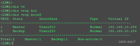
6. VRRP 配置:
LSW1 和 LSW2 分别存在 Vlanif10、20,分别作为部门 A、B 的网关, 要求使用 VRRP 技术实现网关的冗余备份。
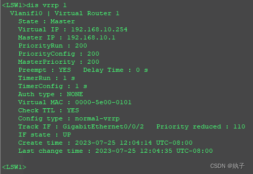
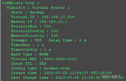
Vlanif10 使 用 的 VRRP 虚 拟 ID 为 1 , 虚 拟 IP 地 址 为 192.168.10.254,LSW1 作为 master 路由,LSW2 作为 backup,master 路由器优先级为 200。
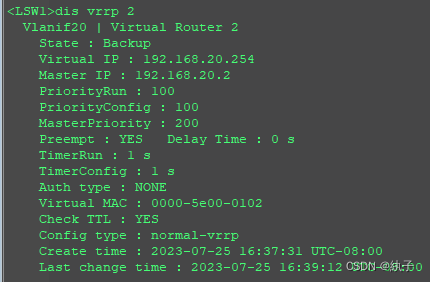
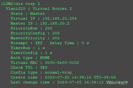
Vlanif20 使 用 的 VRRP 虚 拟 ID 为 2 , 虚 拟 IP 地 址 为 192.168.20.254,LSW2 作为 master 路由,LSW1 作为 backup,master 路由器优先级为 200。
在 Vlanif10 和 20 的 master 路由器分别使用 BFD 技术跟踪上行接口, 当上行链路断开时,能自动切换到备份路由器。
①
LSW1
interface Vlanif10
 vrrp vrid 1 virtual-ip 192.168.10.254
 vrrp vrid 1 priority 200
interface Vlanif20
vrrp vrid 2 virtual-ip 192.168.20.254| 命令 | 作用 |
|---|---|
| interface Vlanif10 | 进入 VLAN 10 虚拟接口的配置模式 |
| vrrp vrid 1 virtual-ip 192.168.10.254 | 配置 VLAN 10 的虚拟路由器 ID 为 1,虚拟 IP 地址为 192.168.10.254 |
| vrrp vrid 1 priority 200 | 配置 VLAN 10 的虚拟路由器优先级为 200 |
| interface Vlanif20 | 进入 VLAN 20 虚拟接口的配置模式 |
| ip address 192.168.20.1 255.255.255.0 | 配置 VLAN 20 虚拟接口的 IP 地址为 192.168.20.1/24 |
| vrrp vrid 2 virtual-ip 192.168.20.254 | 配置 VLAN 20 的虚拟路由器 ID 为 2,虚拟 IP 地址为 192.168.20.254 |
LSW2
interface Vlanif10
 vrrp vrid 1 virtual-ip 192.168.10.254
interface Vlanif20
 vrrp vrid 2 virtual-ip 192.168.20.254
vrrp vrid 2 priority 200| 命令 | 作用 |
|---|---|
| interface Vlanif10 | 进入 VLAN 10 虚拟接口的配置模式 |
| vrrp vrid 1 virtual-ip 192.168.10.254 | 配置 VLAN 10 的虚拟路由器 ID 为 1,虚拟 IP 地址为 192.168.10.254 |
| interface Vlanif20 | 进入 VLAN 20 虚拟接口的配置模式 |
| vrrp vrid 2 virtual-ip 192.168.20.254 | 配置 VLAN 20 的虚拟路由器 ID 为 2,虚拟 IP 地址为 192.168.20.254 |
| vrrp vrid 2 priority 200 | 配置 VLAN 20 的虚拟路由器优先级为 200 |
②在 Vlanif10 和 20 的 master 路由器分别使用 BFD 技术跟踪上行接口, 当上行链路断开时,能自动切换到备份路由器。
LSW1:
interface Vlanif10
 vrrp vrid 1 track interface GigabitEthernet0/0/2 reduced 110
| 命令 | 作用 |
|---|---|
| interface Vlanif10 | 进入 VLAN 10 虚拟接口的配置模式 |
| vrrp vrid 1 track interface GigabitEthernet0/0/2 reduced 110 | 配置 VLAN 10 的虚拟路由器跟踪接口 GigabitEthernet0/0/2 的状态,当该接口状态发生改变时,将降低 VLAN 10 的虚拟路由器优先级 110 |
LSW2:
interface Vlanif20
 vrrp vrid 2 track interface GigabitEthernet0/0/1 reduced 110
配置结果:

7. IGP 配置
LSW1,LSW2,AR1 运行 OSPF,进程号为 1,处于区域 0
AR1:
ospf 1 router-id 1.1.1.1
 area 0.0.0.0
  network 192.168.11.0 0.0.0.255
  network 192.168.13.0 0.0.0.255
LSW1:
ospf 1 router-id 2.2.2.2
 area 0.0.0.0
  network 192.168.11.0 0.0.0.255
  network 192.168.13.0 0.0.0.255
  network 192.168.30.0 0.0.0.255
  network 192.168.10.0 0.0.0.255
  network 192.168.20.0 0.0.0.255
LSW2:
ospf 1 router-id 3.3.3.3
 area 0.0.0.0
  network 192.168.11.0 0.0.0.255
  network 192.168.13.0 0.0.0.255
  network 192.168.30.0 0.0.0.255
  network 192.168.10.0 0.0.0.255
network 192.168.20.0 0.0.0.255| 命令 | 作用 |
|---|---|
| ospf 1 router-id 3.3.3.3 | 配置 OSPF 进程的路由器 ID 为 3.3.3.3 |
| area 0.0.0.0 | 进入 OSPF 进程的区域 0 配置模式 |
| network 192.168.11.0 0.0.0.255 | 配置网络 192.168.11.0/24 参与 OSPF 进程的区域 0 |
| network 192.168.13.0 0.0.0.255 | 配置网络 192.168.13.0/24 参与 OSPF 进程的区域 0 |
| network 192.168.30.0 0.0.0.255 | 配置网络 192.168.30.0/24 参与 OSPF 进程的区域 0 |
| network 192.168.10.0 0.0.0.255 | 配置网络 192.168.10.0/24 参与 OSPF 进程的区域 0 |
| network 192.168.20.0 0.0.0.255 | 配置网络 192.168.20.0/24 参与 OSPF 进程的区域 0 |
8. DHCP 配置
AR1 为 DHCP 服务器,为部门 A 和部门 B 的主机分配 IP 地址,采用基 于全局地址池的分配方式,创建 ip pool A 为部门 A 分配 IP 地址:网段 为 192.168.10.0/24,网关为:192.168.10.254,DNS 为:8.8.8.8;创 建 ip pool B 为部门 B 分配 IP 地址:网段为 192.168.20.0/24,网关为: 192.168.20.254,DNS 为:114.114.114.114;
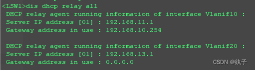
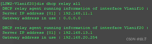
LSW1 和 LSW2 为 DHCP 中继器,VLANif10 指向的 DHCP 服务器的地 址为:192.168.11.1, VLANif20 指向的 DHCP 服务器的地址为: 192.168.13.1。
AC为DHCP服务器,为AP分配IP地址
AR1:
dhcp enable
ip pool vlan10
 gateway-list 192.168.10.254
 network 192.168.10.0 mask 255.255.255.0
 dns-list 8.8.8.8
ip pool vlan20
 gateway-list 192.168.20.254
 network 192.168.20.0 mask 255.255.255.0
 dns-list 114.114.114.114
interface GigabitEthernet0/0/0
 dhcp select global
interface GigabitEthernet0/0/1
dhcp select global| 命令 | 作用 |
|---|---|
| dhcp enable | 启用 DHCP 服务 |
| ip pool vlan10 | 创建名为 vlan10 的 IP 地址池 |
| gateway-list 192.168.10.254 | 配置 IP 地址池的默认网关为 192.168.10.254 |
| network 192.168.10.0 mask 255.255.255.0 | 配置 IP 地址池的网络地址为 192.168.10.0/24 |
| dns-list 8.8.8.8 | 配置 IP 地址池的 DNS 服务器地址为 8.8.8.8 |
| ip pool vlan20 | 创建名为 vlan20 的 IP 地址池 |
| gateway-list 192.168.20.254 | 配置 IP 地址池的默认网关为 192.168.20.254 |
| network 192.168.20.0 mask 255.255.255.0 | 配置 IP 地址池的网络地址为 192.168.20.0/24 |
| dns-list 114.114.114.114 | 配置 IP 地址池的 DNS 服务器地址为 114.114.114.114 |
| interface GigabitEthernet0/0/0 | 进入接口 GigabitEthernet0/0/0 的配置模式 |
| dhcp select global | 配置接口 GigabitEthernet0/0/0 使用全局 DHCP 配置 |
| interface GigabitEthernet0/0/1 | 进入接口 GigabitEthernet0/0/1 的配置模式 |
| dhcp select global | 配置接口 GigabitEthernet0/0/1 使用全局 DHCP 配置 |
LSW1&LSW2:
interface Vlanif10
 dhcp select relay
 dhcp relay server-ip 192.168.11.1
interface Vlanif20
 dhcp select relay
dhcp relay server-ip 192.168.13.1| 命令 | 作用 |
|---|---|
| interface Vlanif10 | 进入 VLANIF 接口 Vlanif10 的配置模式 |
| dhcp select relay | 配置 Vlanif10 为 DHCP 中继代理 |
| dhcp relay server-ip 192.168.11.1 | 配置 Vlanif10 使用 IP 地址为 192.168.11.1 的 DHCP 服务器 |
| interface Vlanif20 | 进入 VLANIF 接口 Vlanif20 的配置模式 |
| dhcp select relay | 配置 Vlanif20 为 DHCP 中继代理 |
| dhcp relay server-ip 192.168.13.1 | 配置 Vlanif20 使用 IP 地址为 192.168.13.1 的 DHCP 服务器 |
配置结果:
9.AP上线
创建AP组,名称为AP;AP认证方式为MAC认证;按拓扑为各AP命名,并添加到AP组下;配置capwap隧道地址为192.168.30.1,查看AP上线情况。
AC1:
interface Vlanif30
 dhcp select interface
capwap source interface vlanif30
wlan
ap-group name ap1
 quit
ap-id 1 ap-mac 00e0-fc84-0260
 ap-name ap1
 ap-group ap1
 quit
ap-group name ap2
 quit
ap-id 2 ap-mac 00e0-fca4-2500
 ap-name ap2
 ap-group ap2
quit | 命令 | 作用 |
|---|---|
| interface Vlanif30 | 进入 VLANIF 接口 Vlanif30 的配置模式 |
| dhcp select interface | 配置 Vlanif30 使用接口地址作为 DHCP 服务器 |
| capwap source interface vlanif30 | 配置 Vlanif30 作为 CAPWAP 控制消息的源接口 |
| wlan | 进入 WLAN 配置模式 |
| ap-group name ap1 | 创建名为 ap1 的 AP 组 |
| quit | 退出 WLAN 配置模式 |
| ap-id 1 ap-mac 00e0-fc84-0260 | 配置 AP 的 ID 为 1,MAC 地址为 00e0-fc84-0260 |
| ap-name ap1 | 配置 AP 的名称为 ap1 |
| ap-group ap1 | 将 AP 加入到 ap1 组中 |
| quit | 退出 AP 配置模式 |
| ap-group name ap2 | 创建名为 ap2 的 AP 组 |
| quit | 退出 WLAN 配置模式 |
| ap-id 2 ap-mac 00e0-fca4-2500 | 配置 AP 的 ID 为 2,MAC 地址为 00e0-fca4-2500 |
| ap-name ap2 | 配置 AP 的名称为 ap2 |
| ap-group ap2 | 将 AP 加入到 ap2 组中 |
| quit | 退出 AP 配置模式 |
上线结果:状态为nor即为上线成功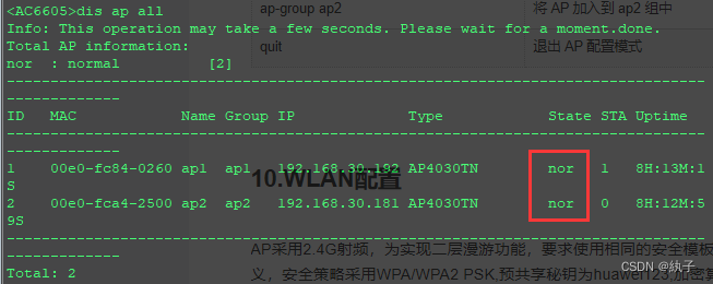
10.WLAN配置
AP采用2.4G射频,为实现二层漫游功能,要求使用相同的安全模板和SSID模板,模板名称自定义,安全策略采用WPA/WPA2 PSK,预共享秘钥为huawei123,加密算法为AES;SSID为huawei,转发方式为直接转发;采用VLAN-POOL分配VLAN10和VLAN20,VLAN分配方式为HASH;为防止AP信号干扰,AP1使用信道1,AP2使用5号信道。
AC1:
wlan
ssid-profile name ap
 ssid 11111
 quit
security-profile name ap
 security wpa-wpa2 psk pass-prase huawei123 aes
 quit
quit
vlan pool ap
 vlan 10 20
 assignment hash
 quit
wlan
vap-profile name ap
 ssid-profile ap
 security-profile ap
 service-vlan vlan-pool ap
 quit
ap-group name ap1
 vap-profile ap wlan 1 radio 0
 quit
ap-group name ap2
 vap-profile ap wlan 1 radio 0
quit| 命令 | 作用 |
|---|---|
| wlan | 进入 WLAN 配置模式 |
| ssid-profile name ap | 创建名为 ap 的 SSID 配置文件 |
| ssid 11111 | 配置 SSID 为 11111 |
| quit | 退出 SSID 配置模式 |
| security-profile name ap | 创建名为 ap 的安全配置文件 |
| security wpa-wpa2 psk pass-prase huawei123 aes | 配置安全配置文件为 WPA/WPA2 PSK 认证,密码为 huawei123,加密算法为 AES |
| quit | 退出安全配置模式 |
| quit | 退出 WLAN 配置模式 |
| vlan pool ap | 创建名为 ap 的 VLAN 池 |
| vlan 10 20 | 配置 VLAN 池包含 VLAN 10 和 VLAN 20 |
| assignment hash | 配置 VLAN 分配方式为哈希分配 |
| quit | 退出 VLAN 池配置模式 |
| wlan | 进入 WLAN 配置模式 |
| vap-profile name ap | 创建名为 ap 的 VAP 配置文件 |
| ssid-profile ap | 配置 VAP 使用 ap SSID 配置文件 |
| security-profile ap | 配置 VAP 使用 ap 安全配置文件 |
| service-vlan vlan-pool ap | 配置 VAP 使用 ap VLAN 池 |
| quit | 退出 VAP 配置模式 |
| ap-group name ap1 | 创建名为 ap1 的 AP 组 |
| vap-profile ap wlan 1 radio 0 | 配置 AP1 使用 ap 的 VAP 配置文件,WLAN ID 为 1,无线电 ID 为 0 |
| quit | 退出 AP 配置模式 |
| ap-group name ap2 | 创建名为 ap2 的 AP 组 |
| vap-profile ap wlan 1 radio 0 | 配置 AP2 使用 ap 的 VAP 配置文件,WLAN ID 为 1,无线电 ID 为 0 |
| quit | 退出 AP 配置模式 |
为防止AP信号干扰,AP1使用信道1,AP2使用5号信道:
wlan
 ap-group name ap2
  radio 0
channel 20mhz 5| 命令 | 作用 |
|---|---|
| wlan | 进入 WLAN 配置模式 |
| ap-group name ap2 | 进入名为 ap2 的 AP 组的配置模式 |
| radio 0 | 进入 Radio 0 的配置模式 |
| channel 20mhz 5 | 配置频道为 5,带宽为 20MHz |
至此,大功告成: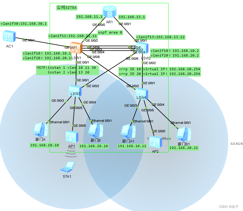


 1532
1532

 被折叠的 条评论
为什么被折叠?
被折叠的 条评论
为什么被折叠?
 到【灌水乐园】发言


