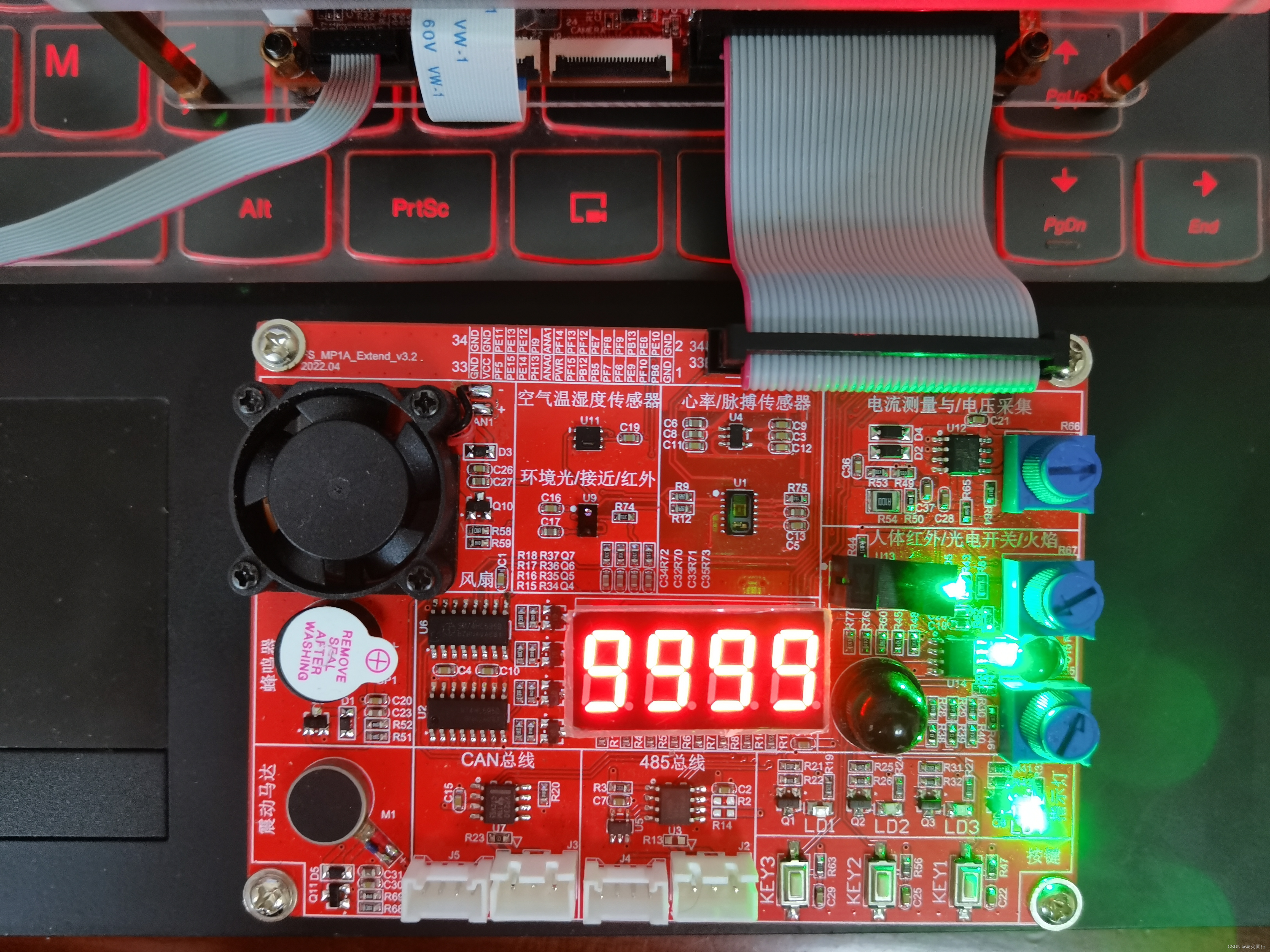
工作原理:

实现代码:
#ifndef __SPI_H__
#define __SPI_H__

#include "stm32mp1xx_gpio.h"
#include "stm32mp1xx_rcc.h"
// MOSI对应的引脚输出高低电平的信号
#define  MOSI_OUTPUT_H()	do{GPIOE->ODR |= (0x1 << 14);}while(0)
#define  MOSI_OUTPUT_L()    do{GPIOE->ODR &= (~(0x1 << 14));}while(0)

// 对应595芯片的锁存引脚输出高低电平
#define  NSS_OUTPUT_H()	    do{GPIOE->ODR |= (0x1 << 11);}while(0)
#define  NSS_OUTPUT_L()     do{GPIOE->ODR &= (~(0x1 << 11));}while(0)

// 时钟信号对应的引脚输出高低电平
#define  SCK_OUTPUT_H()     do{GPIOE->ODR |= (0x1 << 12);}while(0)
#define  SCK_OUTPUT_L()     do{GPIOE->ODR &= (~(0x1 << 12));}while(0)

/*
 * 函数功能: SPI初始化函数,推挽输出,高速,禁止上拉和下拉
 * 函数参数:无
 * 函数返回值:无
*/
void SPI_init(void);
/*
 * 函数功能:SPI发送数据的函数
 * 函数参数:dat : 要发送的数据
 * 函数返回值:无
 *
*/
void SPI_write(unsigned char dat);


#endif  // __SPI_H__
#include "spi.h"
/* SPI4_NSS 	---->   PE11
 * SPI4_SCK     ---->   PE12
 * SPI4_MOSI    ---->   PE14
 * SPI4_MISO    ---->   PE13
 * */

/* 数码管的编码, 先发送低位,在发送高位
 * A B C D E F G DP
 * 1 1 1 1 1 1 0 0    0xFC   0
 * 0 1 1 0 0 0 0 0    0x60   1
 * 1 1 0 1 1 0 1 0    0xDA   2
 * 1 1 1 1 0 0 1 0    0xF2   3
 * 0 1 1 0 0 1 1 0    0x66   4
 * 1 0 1 1 0 1 1 0    0xB6   5
 * 1 0 1 1 1 1 1 0    0xBE   6
 * 1 1 1 0 0 0 0 0    0xE0   7
 * 1 1 1 1 1 1 1 0    0xFE   8
 * 1 1 1 1 0 1 1 0    0xF6   9
 * */
void delay_us1(unsigned int us)
{
	int i,j;
	for(i = 0; i < us;i++)
		for (j = 0; j < 1;j++);
}

void SPI_init(void)
{
	RCC->MP_AHB4ENSETR |= (0x1 << 4);
	// MOSI    PE14
	GPIOE->MODER &= (~(0x3 << 28));
	GPIOE->MODER |= (0x1 << 28);
	GPIOE->OTYPER &= (~(0x1 << 14));
	GPIOE->OSPEEDR &= (~(0x3 << 28));
//	GPIOE->OSPEEDR |= (0x2 << 28);
	GPIOE->PUPDR &= (~(0x3 << 28));
	// MISO    PE13
	GPIOE->MODER &= (~(0x3 << 26));
	GPIOE->OSPEEDR &= (~(0x3 << 26));
//	GPIOE->OSPEEDR |= (0x2 << 26);
	GPIOE->PUPDR &= (~(0x3 << 26));
	// SCK     PE12
	GPIOE->MODER &= (~(0x3 << 24));
	GPIOE->MODER |= (0x1 << 24);
	GPIOE->OTYPER &= (~(0x1 << 12));
	GPIOE->OSPEEDR &= (~(0x3 << 24));
//	GPIOE->OSPEEDR |= (0x2 << 24);
	GPIOE->PUPDR &= (~(0x3 << 24));
	// NSS     PE11
	GPIOE->MODER &= (~(0x3 << 22));
	GPIOE->MODER |= (0x1 << 22);
	GPIOE->OTYPER &= (~(0x1 << 11));
	GPIOE->OSPEEDR &= (~(0x3 << 22));
//	GPIOE->OSPEEDR |= (0x2 << 22);
	GPIOE->PUPDR &= (~(0x3 << 22));
	NSS_OUTPUT_L();    // 595芯片的锁存引脚拉低
	SCK_OUTPUT_L();    // SPI的时钟线拉低
}

void SPI_write(unsigned char dat)
{
	unsigned char i;
	for(i = 0; i < 8; i++)
	{

		if(dat & 0x01)
		{
			MOSI_OUTPUT_H();  // MOSI线写高
		} else {
			MOSI_OUTPUT_L();  // MOSI线写低
		}
		dat >>= 1;
		// 时钟线从低电平到高电平的变化时,MOSI数据线上的数据
		// 被写到595芯片的移位寄存器中
		SCK_OUTPUT_L();   // SCK拉低
		delay_us1(10);
		SCK_OUTPUT_H();   // SCK拉高
		delay_us1(10);
	}
	//NSS_OUTPUT_L();
	//NSS_OUTPUT_H();

}
#include "gpio.h"
#include "uart4.h"
#include "command.h"
#include "beep.h"
#include "key-TI.h"
#include "si7006.h"
#include "spi.h"
extern void printf(const char *fmt, ...);
void delay_ms(int ms)
{

	int i,j;
	for(i = 0; i < ms;i++)
		for (j = 0; j < 1800; j++);
}
void led_init(void)
{
	RCC_MP_AHB4ENSETR |= (0x3 << 4);
	// gpio_init_t init = {GPIO_OUTPUT,GPIO_PP,LOW_SPEED,NOPUPD};
	/*
	gpio_init_t init;
	init.mode = GPIO_OUTPUT;
	init.type = GPIO_PP;
	init.speed = LOW_SPEED;
	init.pupd = NOPUPD;
*/
	gpio_init_t gpio_init = {
		.mode = GPIO_OUTPUT,
		.type = GPIO_PP,
		.speed = LOW_SPEED,
		.pupd = NOPUPD,
	};
	hal_gpio_init(GPIOE, &gpio_init, GPIO_PIN_10);
	hal_gpio_init(GPIOF, &gpio_init, GPIO_PIN_10);
	hal_gpio_init(GPIOE, &gpio_init, GPIO_PIN_8);
}

void led_flash(void)
{
	hal_gpio_write(GPIOE, GPIO_PIN_10, GPIO_SET);
	delay_ms(500);
	hal_gpio_write(GPIOE, GPIO_PIN_10, GPIO_RESET);
	delay_ms(500);
}
int num[10] = {0xFC,0x60,0xDA,0xF2,0x66,0xB6,0xBE,0xE0,0xFE,0xF6};
int main(void)
{
	unsigned char i;
	SPI_init();
	while(1)
	{
#if 1
		for(i = 0; i < 10; i++)
		{
			SPI_write(0xF0);  // 发送数码管的位
			SPI_write(num[i]);  // 发送数码管的段
			NSS_OUTPUT_L();
			delay_ms(1);
			NSS_OUTPUT_H();   // 锁存的时钟从低到高的变化
							// 将移位寄存器中的数据锁存到锁存寄存器中
			delay_ms(1000);
		}
#else
		for(i = 0; i < 4; i++)
		{
			SPI_write(0x80 >> i);
			SPI_write(num[i+1]);
			NSS_OUTPUT_L();
			delay_ms(1);
			NSS_OUTPUT_H();
		}
#endif

	}
	return 0;
}
实验现象:


 618
618

 被折叠的 条评论
为什么被折叠?


