


Answer
Making Ethernet work on STM32H7 can be a bit tricky and requires specific memory configuration. Theory details are explained in separate FAQ: FAQ: Ethernet not working on STM32H7x3.
1. Goal
Goal of this example is to:
- Configure project in STM32CubeMX for STM32H750-Discovery
- Configure FreeRTOS and LwIP middlewares correctly
- Send UDP message periodically
Although the example is using STM32H750-Discovery, it might be easy to use the same steps for other STM32H7 based boards. The main differences are usually pinout and clock configuration. You might also need to check board solder bridges to make sure the Ethernet is connected to MCU.
2. STM32CubeMX project configuration
Create new project in STM32CubeMX, select STM32H750-Discovery board and select "No" to "Initialize all peripherals in default mode?" popup.
This will help with pin assignment.
3. Basic configuration
Configure clock tree
- In pinout/RCC configure HSE in bypass mode
- In clock tree configure 400MHz for core

In Pinout SYS configure differnet timebase than SysTick (recommended when using FreeRTOS)
4. Ethernet configuration
Enable Ethernet peripheral in pinout view in MII mode (MII used on the board).
Enable Ethernet interrupt and set preemption priority to 5. This is required by FreeRTOS in order to call its functions from interrupt handler.
Relocate Ethernet CRS and COL signals from PH2/PH3 to PA0/PA3
- These signals are optional in full-duplex mode and not connected in default configuration
- This will also allow use PH2/PH3 for QSPI
Other pins should be correctly placed, since we create the project from board selector.
- Set GPIO pin speed to Very High.
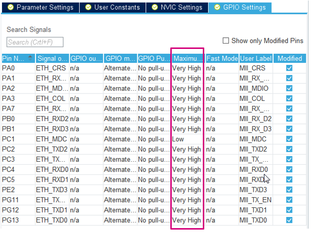

The ETH_MDC speed can't be changed for some reason, but it doesn't affect the application.
5. Cortex-M7 configuration
Enable ICache and DCache.
Enable memory protection unit (MPU) in “Background Region Privileged access only + MPU Disabled ...” mode. Configure regions according to the picture below.
6. FreeRTOS configuration
Enable the FreeRTOS with CMSIS_V1 API.
Increase the size of defaultTask stack to 256 words
- Lower stack values cause memory corruptions
- Please check also that the generated code is correct, since there is bug when increasing the MINIMAL_STACK_SIZE and there might be old value in code

7. LwIP configuration
Enable LwIP in middleware.
In "General settings" tab, disable DHCP server and configure fixed IP address (unless you know how to configure and use DHCP).
In "Platform settings" tab select "LAN8742" in both select boxes. The LAN8742 driver is also compatible with LAN8740 device, which is actually present on the STM32H750-Discovery board. The main difference between these devices is support of MII interface.
In "Checksum" tab enable CHECKSUM_BY_HARDWARE. Other options should automatically reconfigure and you can leave them in this state.
In "Key options" tab:
- Configure MEM_SIZE to 16360. This specifies the heap size, which we will relocated to D2 SRAM (16kb minus 24 bytes for allocator metadata).
- Also enable LWIP_NETIF_LINK_CALLBACK (needed for cable plugging/unplugging detection).
8. Generate project
Save project to some folder of your selection. Now you can generate the project for IDE. We will use STM32CubeIDE in this example, but it should work with other IDEs.
9. Modyfying the code (STM32CubeIDE)
Add following code to lwipopts.h in user section, which will relocated LwIP heap to D2 SRAM:
/* USER CODE BEGIN 1 */
#define LWIP_RAM_HEAP_POINTER (0x30044000)
/* USER CODE END 1 */
Add DATA_IN_D2_SRAM to macro definitions in project:
Modify linkerscript (not valid for Keil/IAR)
This step should be skipped for Keil and IAR, since they support placing variables at specific address in C code.
Modify the linkerscript (*.ld) that the ETH descriptors and buffers are located in D2 SRAM. Also it is recommended to place all RAM to RAM_D1.
In STM32CubeMX generated project, the "_FLASH" suffix linkerscript should be modified, which is used by default (e.g.: STM32H750XBHx_FLASH.ld). The "_RAM" suffix linkerscript is template for executing code from internal RAM memory.
  } >RAM_D1

  /* Modification start */
  .lwip_sec (NOLOAD) : {
    . = ABSOLUTE(0x30040000);
    *(.RxDecripSection)

    . = ABSOLUTE(0x30040060);
    *(.TxDecripSection)

    . = ABSOLUTE(0x30040200);
    *(.RxArraySection)
  } >RAM_D2
  /* Modification end */

  /* Remove information from the compiler libraries */
  /DISCARD/ :
  {
    libc.a ( * )
    libm.a ( * )
    libgcc.a ( * )
  }
The memory definitions at the beginning of the linkerscript should look like:
MEMORY
{
    FLASH (rx)      : ORIGIN = 0x08000000, LENGTH = 1024K
    DTCMRAM (xrw)      : ORIGIN = 0x20000000, LENGTH = 128K
    RAM_D1 (xrw)      : ORIGIN = 0x24000000, LENGTH = 512K
    RAM_D2 (xrw)      : ORIGIN = 0x30000000, LENGTH = 288K
    RAM_D3 (xrw)      : ORIGIN = 0x38000000, LENGTH = 64K
    ITCMRAM (xrw)      : ORIGIN = 0x00000000, LENGTH = 64K
}
Adding simple Hello UDP message
Add following include files at the beginning of main.c:
#include “lwip/udp.h”
#include <string.h>
Modify the StartDefaultTask in main.c with the following code:
/* USER CODE BEGIN 5 */
const char* message = "Hello UDP message!\n\r";

osDelay(1000);

ip_addr_t PC_IPADDR;
IP_ADDR4(&PC_IPADDR, 192, 168, 0, 1);

struct udp_pcb* my_udp = udp_new();
udp_connect(my_udp, &PC_IPADDR, 55151);
struct pbuf* udp_buffer = NULL;

/* Infinite loop */
for (;;) {
  osDelay(1000);
  udp_buffer = pbuf_alloc(PBUF_TRANSPORT, strlen(message), PBUF_RAM);
  if (udp_buffer != NULL) {
    memcpy(udp_buffer->payload, message, strlen(message));
    udp_send(my_udp, udp_buffer);
    pbuf_free(udp_buffer);
  }
}
/* USER CODE END 5 */
Now you should be able to ping the device and receive UDP messages, assuming that you configure IP address 192.168.0.1 for the receiving device. On Linux machine you can observe the messages with the following command:
netcat –ul 55151
10. Tips & Tricks
- For STM32H72x/H73x devices, the Ethernet buffers can't be placed in address range 0x30040000 - 0x30048000, since that range is not valid. D2 SRAM on those devices is much smaller, so the buffers need to be placed starting at 0x30000000. This affects RX & TX descriptors and RX buffer addresses (ETH configuration in CubeMX) and LWIP_RAM_HEAP_POINTER used for TX buffers (LWIP > Key options in CubeMX).
- When running the stack on Cortex-M4, the buffers can be placed at the same address (0x30040000), but it is better to place them at 0x10040000 which is alias for the same address. This alias is accessible by Cortex-M4 D-bus and helps to utilize the Harvard architecture.
- When not using FreeRTOS, the Ethernet interrupt should be disabled and MX_LWIP_Process should be called periodically (in main loop).
- On STM32H747-Discovery board, modification needs to be done to default solder bridge configuration. SB8 should be closed and SB21 should be open for Ethernet to work, otherwise the MDC signal is not properly connected.
When facing issues with your own project:
- First try example and see if there is proper configuration on PC side. With corporate firewalls and restrictions, it might be difficult to perform simple ping to specific IP address. In some cases it is easier to test from personal PC, or some PC with firewall disabled.
- Check if Ethernet interrupt is called and if RX callback is called
- If not, GPIOs are set to proper speed (very high)
- and ETH global interrupt is enabled (only for FreeRTOS)
- Interrupt priority should be 5 - preemption and 0 - subpriority. This is required by default FreeRTOS configuration.
- If Hardfault is called, the problem might be in MPU configuration
- Please check carefully (e.g. slight mistake like having "256KB instead "256B" can make big difference)
- RX callback is called but ping still not work
- check that the buffers are properly placed in linkerscript (the one ending with "_FLASH.ld")
- in STM32CubeIDE you can use "Build analyzer" window
11. Attached examples
Attached here are also examples for different STM32H7 Discovery and Nucleo boards. These are minimalistic examples for FreeRTOS and fixed IP address (192.168.1.10). There is no application communication implemented, but the board should react to PING (ICMP) requests. Examples are for STM32CubeIDE v1.6.1 and STM32Cube_FW_H7_V1.9.0.


 2166
2166


 被折叠的 条评论
为什么被折叠?
被折叠的 条评论
为什么被折叠?
 到【灌水乐园】发言


