


本文将实现三维空间中的旋转和平移变换,即将三维空间中的一个向量(或者一个空间图形)移动到另一个位置。如下图所示:
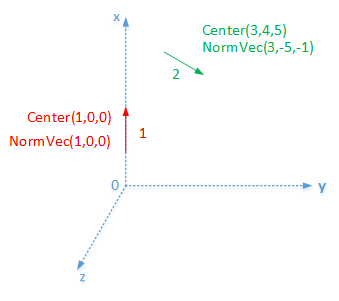
如上图所示,由矢量一移动到矢量二。
三维空间中的移动可以分为旋转和平移。
设矢量一在坐标位置(X0,Y0,Z0) .目标矢量二在坐标位置(X,Y,Z)。
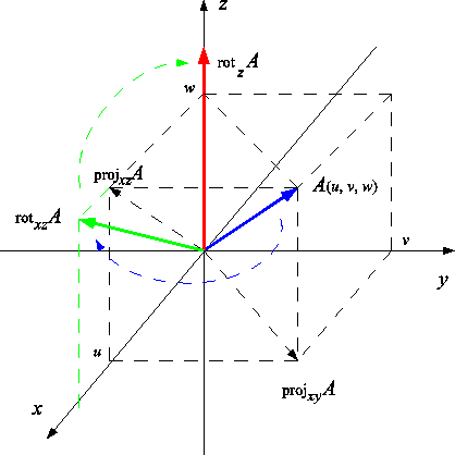
空间任意一个位置的向量移动到与Z轴位置(法失和起点值相同)可以拆分为两步。第一步是绕Z轴旋转到XZ平面,第二步是绕Y轴旋转到Z轴。可以参考如下链接:
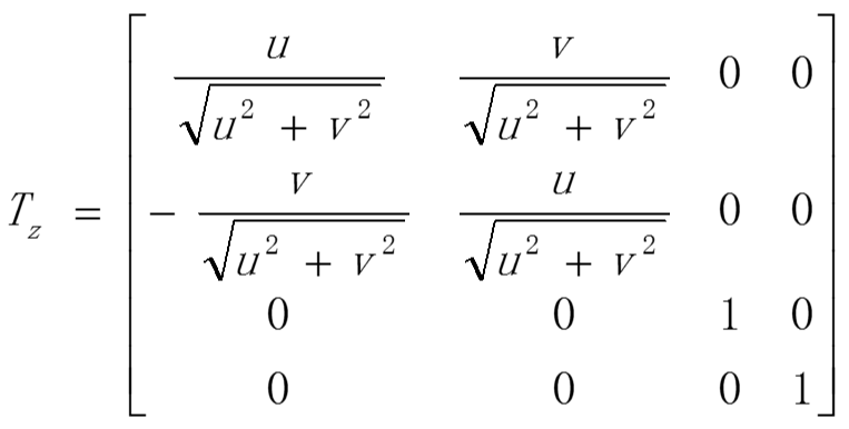
其中,第一步绕Z轴旋转到XZ平面的旋转矩阵如下所示:
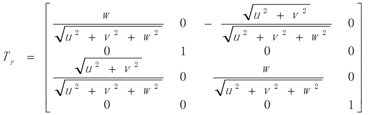
第二步,绕Y轴旋转时,Y的值为0,仅仅在XZ平面内作旋转。旋转矩阵如下:
那么由原点位置任意方向移动到与Z轴正向相同需要经过如下步骤:
(X0,Y0,Z0) = Ty (Tz *(X,Y, Z))
即(X0,Y0,Z0) = Ty Tz (X,Y, Z)
因为任意矢量先要绕Z轴旋转,再绕Y轴旋转 所以为TyTz
那么,现在要将在Z轴正向的矢量移动到空间任意位置 只需要将上式求逆即可
具体如下:
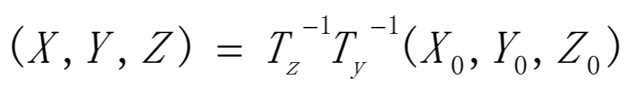
(X,Y, Z) = (Ty Tz)^-1 (X0,Y0,Z0)
即
设空间任意向量法失归一化后表示为u v w
那么
</pre><pre name="code" class="cpp">    a1 = u/sqrt(u*u + v*v);
    a2 = v/sqrt(u*u + v*v);
    a3 = w/sqrt(u*u + v*v + w*w);
    a4 = sqrt(u*u + v*v) / sqrt(u*u + v*v + w*w);

    Tz = [ a1  a2  0
            -a2 a1  0
            0   0   1];

    Ty = [ a3   0   -a4
           0    1   0
           a4   0   a3];
TyTz = [ a1*a3 a2*a3 -a4
-a2 a1 0
a1*a4 a2*a4 a3
];
所以Tz^-1*Ty^-1 = (TyTz)^-1 = (TyTz)^T(这里因为是单位正交矩阵,所以求逆等于求转置)
= [a1*a3 -a2 a1*a4
a2*a3 a1 a2*a4
-a4 0 a3];
最后利用公式即可得到旋转后的矩阵。即
(X,Y, Z) = (Ty Tz)^-1 (X0,Y0,Z0)
实验验证:
定义空间任意位置圆心参数:
center = [3 4 5]';
normVec0 = [3 -5 -1];
radius = 1;
numPts0 = 100;
目标位置为:
center0 = [0 0 1]‘;
normVec = [0 0 1];
代码如下:
clear;close all;
center = [3 4 5]';
normVec0 = [3 -5 -1];
normVec0 = - normVec0 / sqrt(sum(normVec0.^2));
radius = 1;
numPts0 = 100;
normalVec = normVec0;
d = sqrt( sum(normalVec.^2) );
u = normalVec(1) / d;
v = normalVec(2) / d;
w = normalVec(3) / d;

a1 = u/sqrt(u*u + v*v);
a2 = v/sqrt(u*u + v*v);
a3 = w/sqrt(u*u + v*v + w*w);
a4 = sqrt(u*u + v*v) / sqrt(u*u + v*v + w*w);

Tz = [ a1  a2  0
    -a2 a1  0
    0   0   1];

Ty = [ a3   0   -a4
    0    1   0
    a4   0   a3];
invTransMat = Ty*Tz;
transMat = inv(invTransMat);

pi = 3.141592653;
theta = linspace(0, 2*pi, numPts0);

X = radius * cos(theta);
Y = radius * sin(theta);
Z = zeros(1, length(X));
%circlePts0 = bsxfun(@plus, [X; Y; Z], center);
circlePts0 = [X; Y; Z];
circlePts = bsxfun(@plus, transMat * [X; Y; Z], center);
figure;
plot3(circlePts0(1, :), circlePts0(2, :), circlePts0(3, :));grid on;
hold on;
plot3(circlePts(1, :), circlePts(2, :), circlePts(3, :));grid on;
hold on;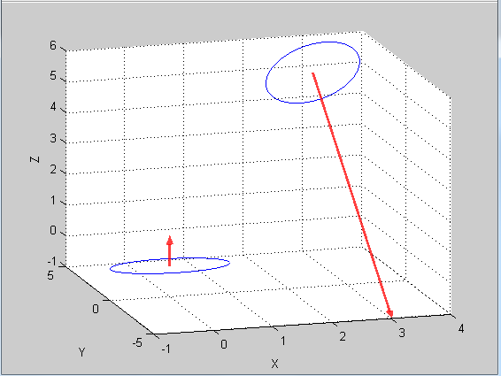
箭头是我自己加上去的:绘制箭头的参考代码如下:
function h = mArrow3(p1,p2,varargin)
%mArrow3 - plot a 3D arrow as patch object (cylinder+cone)
%
% syntax:   h = mArrow3(p1,p2)
%           h = mArrow3(p1,p2,'propertyName',propertyValue,...)
%
% with:     p1:         starting point
%           p2:         end point
%           properties: 'color':      color according to MATLAB specification
%                                     (see MATLAB help item 'ColorSpec')
%                       'stemWidth':  width of the line
%                       'tipWidth':   width of the cone
%
%           Additionally, you can specify any patch object properties. (For
%           example, you can make the arrow semitransparent by using
%           'facealpha'.)
%
% example1: h = mArrow3([0 0 0],[1 1 1])
%           (Draws an arrow from [0 0 0] to [1 1 1] with default properties.)
%
% example2: h = mArrow3([0 0 0],[1 1 1],'color','red','stemWidth',0.02,'facealpha',0.5)
%           (Draws a red semitransparent arrow with a stem width of 0.02 units.)
%
% hint:     use light to achieve 3D impression
%

propertyNames = {'edgeColor'};
propertyValues = {'none'};

%% evaluate property specifications
for argno = 1:2:nargin-2
    switch varargin{argno}
        case 'color'
            propertyNames = {propertyNames{:},'facecolor'};
            propertyValues = {propertyValues{:},varargin{argno+1}};
        case 'stemWidth'
            if isreal(varargin{argno+1})
                stemWidth = varargin{argno+1};
            else
                warning('mArrow3:stemWidth','stemWidth must be a real number');
            end
        case 'tipWidth'
            if isreal(varargin{argno+1})
                tipWidth = varargin{argno+1};
            else
                warning('mArrow3:tipWidth','tipWidth must be a real number');
            end
        otherwise
            propertyNames = {propertyNames{:},varargin{argno}};
            propertyValues = {propertyValues{:},varargin{argno+1}};
    end
end

%% default parameters
if ~exist('stemWidth','var')
    ax = axis;
    if numel(ax)==4
        stemWidth = norm(ax([2 4])-ax([1 3]))/300;
    elseif numel(ax)==6
        stemWidth = norm(ax([2 4 6])-ax([1 3 5]))/300;
    end
end
if ~exist('tipWidth','var')
    tipWidth = 3*stemWidth;
end
tipAngle = 22.5/180*pi;
tipLength = tipWidth/tan(tipAngle/2);
ppsc = 50;  % (points per small circle)
ppbc = 250; % (points per big circle)

%% ensure column vectors
p1 = p1(:);
p2 = p2(:);

%% basic lengths and vectors
x = (p2-p1)/norm(p2-p1); % (unit vector in arrow direction)
y = cross(x,[0;0;1]);    % (y and z are unit vectors orthogonal to arrow)
if norm(y)<0.1
    y = cross(x,[0;1;0]);
end
y = y/norm(y);
z = cross(x,y);
z = z/norm(z);

%% basic angles
theta = 0:2*pi/ppsc:2*pi; % (list of angles from 0 to 2*pi for small circle)
sintheta = sin(theta);
costheta = cos(theta);
upsilon = 0:2*pi/ppbc:2*pi; % (list of angles from 0 to 2*pi for big circle)
sinupsilon = sin(upsilon);
cosupsilon = cos(upsilon);

%% initialize face matrix
f = NaN([ppsc+ppbc+2 ppbc+1]);

%% normal arrow
if norm(p2-p1)>tipLength
    % vertices of the first stem circle
    for idx = 1:ppsc+1
        v(idx,:) = p1 + stemWidth*(sintheta(idx)*y + costheta(idx)*z);
    end
    % vertices of the second stem circle
    p3 = p2-tipLength*x;
    for idx = 1:ppsc+1
        v(ppsc+1+idx,:) = p3 + stemWidth*(sintheta(idx)*y + costheta(idx)*z);
    end
    % vertices of the tip circle
    for idx = 1:ppbc+1
        v(2*ppsc+2+idx,:) = p3 + tipWidth*(sinupsilon(idx)*y + cosupsilon(idx)*z);
    end
    % vertex of the tiptip
    v(2*ppsc+ppbc+4,:) = p2;

    % face of the stem circle
    f(1,1:ppsc+1) = 1:ppsc+1;
    % faces of the stem cylinder
    for idx = 1:ppsc
        f(1+idx,1:4) = [idx idx+1 ppsc+1+idx+1 ppsc+1+idx];
    end
    % face of the tip circle
    f(ppsc+2,:) = 2*ppsc+3:(2*ppsc+3)+ppbc;
    % faces of the tip cone
    for idx = 1:ppbc
        f(ppsc+2+idx,1:3) = [2*ppsc+2+idx 2*ppsc+2+idx+1 2*ppsc+ppbc+4];
    end

%% only cone v
else
    tipWidth = 2*sin(tipAngle/2)*norm(p2-p1);
    % vertices of the tip circle
    for idx = 1:ppbc+1
        v(idx,:) = p1 + tipWidth*(sinupsilon(idx)*y + cosupsilon(idx)*z);
    end
    % vertex of the tiptip
    v(ppbc+2,:) = p2;
    % face of the tip circle
    f(1,:) = 1:ppbc+1;
    % faces of the tip cone
    for idx = 1:ppbc
        f(1+idx,1:3) = [idx idx+1 ppbc+2];
    end
end

%% draw
fv.faces = f;
fv.vertices = v;
h = patch(fv);
for propno = 1:numel(propertyNames)
    try
        set(h,propertyNames{propno},propertyValues{propno});
    catch
        disp(lasterr)
    end
end


 4635
4635

 被折叠的 条评论
为什么被折叠?
被折叠的 条评论
为什么被折叠?
 到【灌水乐园】发言


