


SOC:RK3588
system:Android12
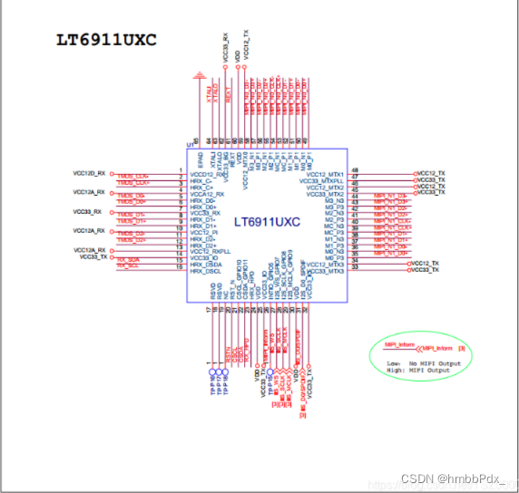
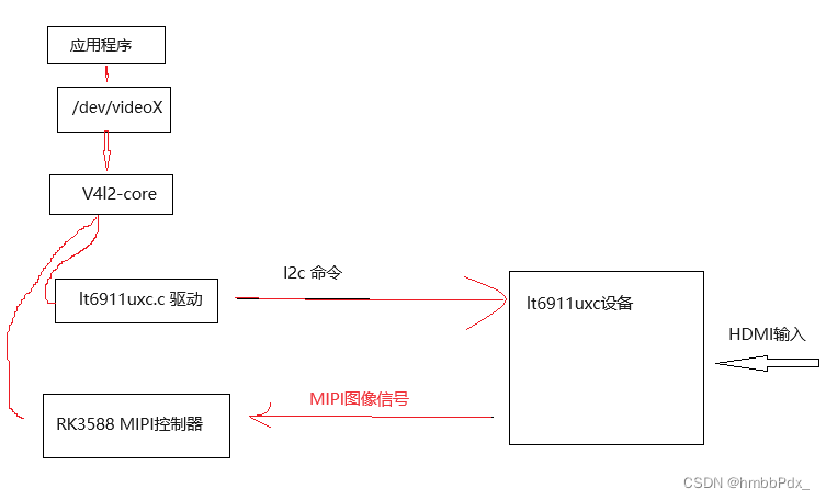
RK3588 项目 , 需要接入HDMI 4k摄像头,把HDMI信号转MIPI信号。
 ’
’
其主要工作流程如下:
DTSI:
I2C 驱动端
&i2c8 {
	status = "okay";
	pinctrl-names = "default";
	pinctrl-0 = <&i2c8m3_xfer>;
	lt6911uxc: lt6911uxc@2b {
		compatible = "lontium,lt6911uxc";
		status = "okay";
		reg = <0x2b>;
        //使用GPIO CLK==========
        pinctrl-names = "default";
		pinctrl-0 = <&mipim1_camera1_clk>;
		clocks = <&cru CLK_MIPI_CAMARAOUT_M1>;
		clock-names = "xvclk";
        //================

		interrupt-parent = <&gpio3>;
		interrupts = <RK_PD5 IRQ_TYPE_EDGE_RISING>;
		power-domains = <&power RK3588_PD_VI>;

		reset-gpios = <&gpio4 RK_PB5 GPIO_ACTIVE_LOW>;//复位脚
		rockchip,camera-module-index = <0>;
		rockchip,camera-module-facing = "back";
		rockchip,camera-module-name = "lt6911uxc";
		rockchip,camera-module-lens-name = "NC";

        //与RK3588的rkcif 对应起来
		port {
			lt6911uxc_out: endpoint {
				remote-endpoint = <&mipi_in_ucam>;
				data-lanes = <1 2 3 4>;
			};
		};
	};
};
MIPI端:
&csi2_dphy0_hw {
status = "okay";
};
&csi2_dphy0 {
status = "okay";
ports {
#address-cells = <1>;
#size-cells = <0>;
port@0 {
reg = <0>;
#address-cells = <1>;
#size-cells = <0>;
mipi_in_ucam: endpoint@1 {
reg = <1>;
remote-endpoint = <<6911uxc_out>;//lt6911uxc i2c驱动匹配起来
data-lanes = <1 2 3 4>;
};
};
port@1 {
reg = <1>;
#address-cells = <1>;
#size-cells = <0>;
csidphy1_out: endpoint@0 {
reg = <0>;
remote-endpoint = <&mipi2_csi2_input>;
};
};
};
};
&mipi2_csi2 {
status = "okay";
ports {
#address-cells = <1>;
#size-cells = <0>;
port@0 {
reg = <0>;
#address-cells = <1>;
#size-cells = <0>;
mipi2_csi2_input: endpoint@1 {
reg = <1>;
remote-endpoint = <&csidphy1_out>;
};
};
port@1 {
reg = <1>;
#address-cells = <1>;
#size-cells = <0>;
mipi2_csi2_output: endpoint@0 {
reg = <0>;
remote-endpoint = <&cif_mipi_in2>;
};
};
};
};
&rkcif {
status = "okay";
};
&rkcif_mipi_lvds2 {
status = "okay";
port {
cif_mipi_in2: endpoint {
remote-endpoint = <&mipi2_csi2_output>;
};
};
};
&rkcif_mmu {
status = "okay";
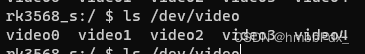
};MIPI 设备树配置好后会在/dev产生 多个video个节点
开机流程:static int lt6911uxc_probe(struct i2c_client *client,
const struct i2c_device_id *id)
1.赋值变量 默认参数 分辨率 MIPI 数据格式
2.lt6911uxc_parse_of 上电复位初始化时钟
3.I2C读取芯片ID,如果失败返回
4.注册V4L2
5.初始化lt6911uxc_delayed_work_res_change 工作队列
lt6911uxc_delayed_work_res_change左右循环读取HDMI输入的信号 图像长宽 格式
static int lt6911uxc_probe(struct i2c_client *client,
const struct i2c_device_id *id)
{
struct v4l2_dv_timings default_timing =
V4L2_DV_BT_CEA_640X480P59_94;
struct lt6911uxc *lt6911uxc;
struct v4l2_subdev *sd;
struct device *dev = &client->dev;
char facing[2];
int err;
dev_info(dev, "driver version: %02x.%02x.%02x",
DRIVER_VERSION >> 16,
(DRIVER_VERSION & 0xff00) >> 8,
DRIVER_VERSION & 0x00ff);
lt6911uxc = devm_kzalloc(dev, sizeof(struct lt6911uxc), GFP_KERNEL);
if (!lt6911uxc)
return -ENOMEM;
sd = <6911uxc->sd;
lt6911uxc->i2c_client = client;
lt6911uxc->timings = default_timing;
lt6911uxc->cur_mode = &supported_modes[0]; //支持4K分辨率
lt6911uxc->mbus_fmt_code = LT6911UXC_MEDIA_BUS_FMT; // MIPI数据格式
err = lt6911uxc_parse_of(lt6911uxc);
if (err) {
v4l2_err(sd, "lt6911uxc_parse_of failed! err:%d\n", err);
return err;
}
//获取芯片ID
err = lt6911uxc_check_chip_id(lt6911uxc);
if (err < 0)
return err;
/* after the CPU actively accesses the lt6911uxc through I2C,
* a reset operation is required.
*/
//复位
lt6911uxc_reset(lt6911uxc);
mutex_init(<6911uxc->confctl_mutex);
//V4l2注册
err = lt6911uxc_init_v4l2_ctrls(lt6911uxc);
if (err)
goto err_free_hdl;
client->flags |= I2C_CLIENT_SCCB;
#ifdef CONFIG_VIDEO_V4L2_SUBDEV_API
v4l2_i2c_subdev_init(sd, client, <6911uxc_ops);
sd->flags |= V4L2_SUBDEV_FL_HAS_DEVNODE | V4L2_SUBDEV_FL_HAS_EVENTS;
#endif
#if defined(CONFIG_MEDIA_CONTROLLER)
lt6911uxc->pad.flags = MEDIA_PAD_FL_SOURCE;
sd->entity.function = MEDIA_ENT_F_CAM_SENSOR;
err = media_entity_pads_init(&sd->entity, 1, <6911uxc->pad);
if (err < 0) {
v4l2_err(sd, "media entity init failed! err: %d\n", err);
goto err_free_hdl;
}
#endif
memset(facing, 0, sizeof(facing));
if (strcmp(lt6911uxc->module_facing, "back") == 0)
facing[0] = 'b';
else
facing[0] = 'f';
snprintf(sd->name, sizeof(sd->name), "m%02d_%s_%s %s",
lt6911uxc->module_index, facing,
LT6911UXC_NAME, dev_name(sd->dev));
err = v4l2_async_register_subdev_sensor_common(sd);
if (err < 0) {
v4l2_err(sd, "v4l2 register subdev failed! err:%d\n", err);
goto err_clean_entity;
}
INIT_DELAYED_WORK(<6911uxc->delayed_work_enable_hotplug,
lt6911uxc_delayed_work_enable_hotplug);
INIT_DELAYED_WORK(<6911uxc->delayed_work_res_change,
lt6911uxc_delayed_work_res_change);
if (lt6911uxc->i2c_client->irq) {
v4l2_dbg(1, debug, sd, "cfg lt6911uxc irq!\n");
err = devm_request_threaded_irq(dev,
lt6911uxc->i2c_client->irq,
NULL, lt6911uxc_res_change_irq_handler,
IRQF_TRIGGER_FALLING | IRQF_ONESHOT,
"lt6911uxc", lt6911uxc);
if (err) {
v4l2_err(sd, "request irq failed! err:%d\n", err);
goto err_work_queues;
}
} else {
err = -EINVAL;
v4l2_err(sd, "no irq cfg failed!\n");
goto err_work_queues;
}
lt6911uxc->plugin_irq = gpiod_to_irq(lt6911uxc->plugin_det_gpio);
if (lt6911uxc->plugin_irq < 0)
dev_err(dev, "failed to get plugin det irq, maybe no use\n");
err = devm_request_threaded_irq(dev, lt6911uxc->plugin_irq, NULL,
plugin_detect_irq_handler, IRQF_TRIGGER_FALLING |
IRQF_TRIGGER_RISING | IRQF_ONESHOT, "lt6911uxc",
lt6911uxc);
if (err)
dev_err(dev, "failed to register plugin det irq (%d), maybe no use\n", err);
err = v4l2_ctrl_handler_setup(sd->ctrl_handler);
if (err) {
v4l2_err(sd, "v4l2 ctrl handler setup failed! err:%d\n", err);
goto err_work_queues;
}
lt6911uxc_config_hpd(sd);
v4l2_info(sd, "%s found @ 0x%x (%s)\n", client->name,
client->addr << 1, client->adapter->name);
return 0;
err_work_queues:
cancel_delayed_work(<6911uxc->delayed_work_enable_hotplug);
cancel_delayed_work(<6911uxc->delayed_work_res_change);
err_clean_entity:
#if defined(CONFIG_MEDIA_CONTROLLER)
media_entity_cleanup(&sd->entity);
#endif
err_free_hdl:
v4l2_ctrl_handler_free(<6911uxc->hdl);
mutex_destroy(<6911uxc->confctl_mutex);
return err;
}主要代码解读:
lt6911uxc_delayed_work_res_change 工作队列会一直重复执行
lt6911uxc_get_detected_timings 获取输入的视频信号
static void lt6911uxc_format_change(struct v4l2_subdev *sd)
{
struct lt6911uxc *lt6911uxc = to_state(sd);
struct v4l2_dv_timings timings;
const struct v4l2_event lt6911uxc_ev_fmt = {
.type = V4L2_EVENT_SOURCE_CHANGE,
.u.src_change.changes = V4L2_EVENT_SRC_CH_RESOLUTION,
};
if (lt6911uxc_get_detected_timings(sd, &timings)) {
enable_stream(sd, false);
v4l2_dbg(1, debug, sd, "%s: No signal\n", __func__);
} else {
if (!v4l2_match_dv_timings(<6911uxc->timings, &z, 0,
false)) {
enable_stream(sd, false);
/* automatically set timing rather than set by user */
lt6911uxc_s_dv_timings(sd, &timings);
v4l2_print_dv_timings(sd->name,
"Format_change: New format: ",
&timings, false);
}
}
if (sd->devnode)//HDMI 信号改变上传
v4l2_subdev_notify_event(sd, <6911uxc_ev_fmt);
}lt6911uxc_get_detected_timings 通过I2C读取视频信号
static int lt6911uxc_get_detected_timings(struct v4l2_subdev *sd,
		struct v4l2_dv_timings *timings)
{
.....

	ret  = i2c_rd8(sd, FW_VER_A, &fw_a);
	ret |= i2c_rd8(sd, FW_VER_B, &fw_b);
	ret |= i2c_rd8(sd, FW_VER_C, &fw_c);
	ret |= i2c_rd8(sd, FW_VER_D, &fw_d);
	if (ret) {
		v4l2_err(sd, "%s: I2C transform err!\n", __func__);
		return -ENOLINK;
	}
	fw_ver = (fw_a << 24) | (fw_b << 16) | (fw_c <<  8) | fw_d;
	v4l2_info(sd, "read fw_version:%#x", fw_ver);
	i2c_wr8(sd, INT_COMPARE_REG, RECEIVED_INT);

	i2c_rd8(sd, INT_STATUS_86A3, &val_h);
	i2c_rd8(sd, INT_STATUS_86A5, &val_l);
	v4l2_info(sd, "int status REG_86A3:%#x, REG_86A5:%#x\n", val_h, val_l);

	i2c_rd8(sd, HDMI_VERSION, &value);
	i2c_rd8(sd, TMDS_CLK_H, &clk_h);
	i2c_rd8(sd, TMDS_CLK_M, &clk_m);
	i2c_rd8(sd, TMDS_CLK_L, &clk_l);
	pixel_clock = (((clk_h & 0xf) << 16) | (clk_m << 8) | clk_l) * 1000;
	if (value & BIT(0)) /* HDMI 2.0 */
		pixel_clock *= 4;

	i2c_rd8(sd, MIPI_LANES, &lanes);
	lt6911uxc->csi_lanes_in_use = lanes;
	i2c_wr8(sd, FM1_DET_CLK_SRC_SEL, AD_LMTX_WRITE_CLK);
	i2c_rd8(sd, FREQ_METER_H, &clk_h);
	i2c_rd8(sd, FREQ_METER_M, &clk_m);
	i2c_rd8(sd, FREQ_METER_L, &clk_l);
	mipi_byte_clk = (((clk_h & 0xf) << 16) | (clk_m << 8) | clk_l);
	mipi_bitrate = mipi_byte_clk * 8 / 1000;
	v4l2_info(sd, "MIPI Byte clk: %dKHz, MIPI bitrate: %dMbps, lanes:%d\n",
			mipi_byte_clk, mipi_bitrate, lanes);

	i2c_rd8(sd, HTOTAL_H, &val_h);
	i2c_rd8(sd, HTOTAL_L, &val_l);
	htotal = ((val_h << 8) | val_l) * 2;
	i2c_rd8(sd, VTOTAL_H, &val_h);
	i2c_rd8(sd, VTOTAL_L, &val_l);
	vtotal = (val_h << 8) | val_l;
	i2c_rd8(sd, HACT_H, &val_h);
	i2c_rd8(sd, HACT_L, &val_l);
	hact = ((val_h << 8) | val_l) * 2;
	i2c_rd8(sd, VACT_H, &val_h);
	i2c_rd8(sd, VACT_L, &val_l);
	vact = (val_h << 8) | val_l;
	i2c_rd8(sd, HS_H, &val_h);
	i2c_rd8(sd, HS_L, &val_l);
	hs = ((val_h << 8) | val_l) * 2;
	i2c_rd8(sd, VS, &value);
	vs = value;
	i2c_rd8(sd, HFP_H, &val_h);
	i2c_rd8(sd, HFP_L, &val_l);
	hfp = ((val_h << 8) | val_l) * 2;
	i2c_rd8(sd, VFP, &value);
	vfp = value;
	i2c_rd8(sd, HBP_H, &val_h);
	i2c_rd8(sd, HBP_L, &val_l);
	hbp = ((val_h << 8) | val_l) * 2;
	i2c_rd8(sd, VBP, &value);
	vbp = value;
	lt6911uxc_i2c_disable(sd);
...


	return 0;
}
当接入HDMI分辨率不同, IC 会自己使用不同Lane个数(越高分辨率的图像会用到越多的lane )
static int lt6911uxc_get_detected_timings(struct v4l2_subdev *sd,
		struct v4l2_dv_timings *timings)
{
    ...

    i2c_rd8(sd, MIPI_LANES, &lanes);
	lt6911uxc->csi_lanes_in_use = lanes;
    ...
}
给lt6911uxc->csi_lanes_in_use赋值后会在lt6911uxc_g_mbus_config 被V4l2打开时获取最终被RKCif驱动所获取使用
static int lt6911uxc_g_mbus_config(struct v4l2_subdev *sd, unsigned int pad,
			     struct v4l2_mbus_config *cfg)
{
	struct lt6911uxc *lt6911uxc = to_state(sd);

	cfg->type = V4L2_MBUS_CSI2_DPHY;
	cfg->flags = V4L2_MBUS_CSI2_CONTINUOUS_CLOCK | V4L2_MBUS_CSI2_CHANNEL_0;

	switch (lt6911uxc->csi_lanes_in_use) {
	case 1:
		cfg->flags |= V4L2_MBUS_CSI2_1_LANE;
		break;
	case 2:
		cfg->flags |= V4L2_MBUS_CSI2_2_LANE;
		break;
	case 3:
		cfg->flags |= V4L2_MBUS_CSI2_3_LANE;
		break;
	case 4:
		cfg->flags |= V4L2_MBUS_CSI2_4_LANE;
		break;

	default:
		return -EINVAL;
	}

	return 0;
}
lt6911uxc_g_mbus_config 函数功能传递MIPI 使用的传输协议 使用LANE个数,多少个通道图像
//传输协议
/**
 * enum v4l2_mbus_type - media bus type
 * @V4L2_MBUS_UNKNOWN:	unknown bus type, no V4L2 mediabus configuration
 * @V4L2_MBUS_PARALLEL:	parallel interface with hsync and vsync
 * @V4L2_MBUS_BT656:	parallel interface with embedded synchronisation, can
 *			also be used for BT.1120
 * @V4L2_MBUS_CSI1:	MIPI CSI-1 serial interface
 * @V4L2_MBUS_CCP2:	CCP2 (Compact Camera Port 2)
 * @V4L2_MBUS_CSI2_DPHY: MIPI CSI-2 serial interface, with D-PHY
 * @V4L2_MBUS_CSI2_CPHY: MIPI CSI-2 serial interface, with C-PHY
 * @V4L2_MBUS_INVALID:	invalid bus type (keep as last)
 */
enum v4l2_mbus_type {
	V4L2_MBUS_UNKNOWN,
	V4L2_MBUS_PARALLEL,
	V4L2_MBUS_BT656,
	V4L2_MBUS_CSI1,
	V4L2_MBUS_CCP2,
	V4L2_MBUS_CSI2_DPHY,
	V4L2_MBUS_CSI2_CPHY,
	V4L2_MBUS_INVALID,
};
//使用到LANE的个数
#define V4L2_MBUS_CSI2_1_LANE           BIT(0)
#define V4L2_MBUS_CSI2_2_LANE           BIT(1)
#define V4L2_MBUS_CSI2_3_LANE           BIT(2)
#define V4L2_MBUS_CSI2_4_LANE           BIT(3)
通道个数,Lt6911只能转换1路
/* CSI-2 Virtual Channel identifiers. */
#define V4L2_MBUS_CSI2_CHANNEL_0		BIT(4)
#define V4L2_MBUS_CSI2_CHANNEL_1		BIT(5)
#define V4L2_MBUS_CSI2_CHANNEL_2		BIT(6)
#define V4L2_MBUS_CSI2_CHANNEL_3		BIT(7)
调试:
读芯片ID失败
1.确认供电是否正常
2.测量时钟脚时钟信号是否达标
无图像:
1.确认MIPI是否有信号
2.lt6911uxc_get_detected_timings里加打印看看能不能获取HDMI的信号格式
使用V4L2 API 即可获取对应的图像,此芯片驱动与一般摄像头视频无太大区别


 1726
1726


 被折叠的 条评论
为什么被折叠?
被折叠的 条评论
为什么被折叠?
 到【灌水乐园】发言


