


单个导线周围不同介质磁场镜像法计算实现
前言
编程实现无限长单根导线在不同介质中的磁场,显示磁感应强度的向量和磁场线
一、镜像法说明
在两种介质中,磁导率分别为μ1和μ2,在介质1内置有电流为 I 的无限长直导线,且平行于分界面,
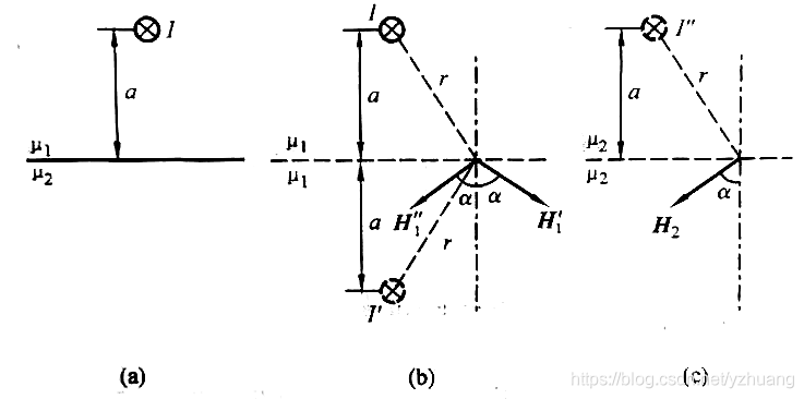
其中:
![]()
![]()
上半部分,电流产生的磁场为:
![]()
下半部分,电流产生的磁场为:
![]()
由于![]() ,得:
,得:
![]()
![]()
二、编程计算磁场
1、定义磁场计算数据结构
struct Wire
{
	double x;
	double y;
	double w;
	double h;
	double J;	// 电密
};

struct Node
{
	Node() { x = y = A=B= α= 0; }
	Node(double x, double y) {
		this->x = x; this->y = y; A = B = α = 0;
	}
	double x;
	double y;
	double A;
	double B;
	double α;
};

struct Edge
{
	Edge() { x1 = x2 = y1 = y2 = 0; }
	double x1;
	double y1;
	double x2;
	double y2;
};

struct Triangle
{
	Triangle() { arNode[0] = NULL, arNode[1] = NULL, arNode[2] = NULL; }
	Triangle(Node* p1, Node* p2, Node* p3) {arNode[0] = p1; arNode[1] = p2; arNode[2] = p3;}
	void GetExtremum(double& nMin, double& nMax) const {
		nMin = nMax= arNode[0]->B;
		for (int i=1; i<3; i++)
		{
			nMin = min(nMin, arNode[i]->B);
			nMax = max(nMax, arNode[i]->B);
		}
	}
	Node* arNode[3];
};

struct Section
{
	double x;
	double y;
	double nWidth;
	double nHeight;
	double nMeshSize;

	double GetMeshSizeX() const {
		return nWidth / int(nWidth / nMeshSize + 0.99);
	}
	double GetMeshSizeY() const {
		return nHeight / int(nHeight / nMeshSize + 0.99);
	}
};
2、定义CFieldData类及相关方法
class CFieldData
{
public:
	CFieldData();
	~CFieldData();

	void Init();
	void CreateFieldMesh(double nMeshSize = 100);
	void CalculteField(const Wire& wire, double μ);
	void CalculteOriginField();
	void CalculteImageField();
	const std::vector<Node>& GetFieldNode() { return m_arFieldNode; }
	const Section& GetFieldArea() { return  m_stFieldArea; }// 场区域
	const Wire& GetWire() { return m_stWire; }

	void DrawGrid(CDC* pDC, CRect rect);
	void DrawVector(CDC* pDC, CRect rect);
	void DrawContour(CDC* pDC, CRect rect);
	void DrawDensity(CDC* pDC, CRect rect);
	void DrawImageLine(CDC* pDC, CRect rect);

	COLORREF GetColor(double nValue) const;
	void DrawContourA(CDC* pDC, CRect rect);
	void DrawContourB(CDC* pDC, CRect rect);

protected:
	double m_nMiu1;
	double m_nMiu2;
	double m_nImageDistance;	// 导线到分界面距离
	Edge m_stBoundary;		// 分接线
	double m_nMinFlux;		// 最小磁感应强度
	double m_nMaxFlux;		// 最大磁感应强度
	int m_nAreaFlag;

	Wire m_stWire;			// 导线
	Section  m_stFieldArea;	// 场区域

	std::vector<Node> m_arFieldNode;
	std::vector<Triangle> m_arTriangles;
};
3、数据初始化
定义一根导线及其位置,以导线为中心,设置一个宽高都为4000计算区域。
void CFieldData::Init()
{
	// 分界面在x轴上
	// 导线距离分界面1000mm
	// 场域宽和高都为4000mm

	m_nMiu1 = 4 * M_PI * 1e-7;	// μ0=4π×10-7 特斯拉·米/安培
	m_nMiu2 = 5 * m_nMiu1;

	m_nImageDistance=600;		// 导线到分界面距离

	m_stWire.x = 1000;		// 导线位置
	m_stWire.y = 1000;
	m_stWire.w = 40; 			// mm;
	m_stWire.J = 3.3;    		// 安培/mm^2

	m_stFieldArea.nWidth = 4000;	// 场区域
	m_stFieldArea.nHeight = 4000;
	m_stFieldArea.x = m_stWire.x - m_stFieldArea.nWidth / 2;
	m_stFieldArea.y = m_stWire.y - m_stFieldArea.nHeight / 2;
	m_stFieldArea.nMeshSize = 100;	// 场域刨分尺寸

	m_stBoundary.x1 = m_stFieldArea.x;			// 分接线
	m_stBoundary.x2 = m_stFieldArea.x + m_stFieldArea.nWidth;
	m_stBoundary.y1 = m_stWire.y - m_nImageDistance;
	m_stBoundary.y2 = m_stBoundary.y1;
}
4、计算区域刨分
先按刨分尺寸分为正方形网格,再把正方形网格分为两个三角形
void CFieldData::CreateFieldMesh(double nMeshSize)
{
	m_stFieldArea.nMeshSize = nMeshSize;

	double x1 = m_stFieldArea.x;
	double y1 = m_stFieldArea.y;
	double x2 = m_stFieldArea.x + m_stFieldArea.nWidth;
	double y2 = m_stFieldArea.y + m_stFieldArea.nHeight;

	double nSizeX = m_stFieldArea.GetMeshSizeX();
	double nSizeY = m_stFieldArea.GetMeshSizeY();

	vector<Node*> arNode1;
	vector<Node*> arNode2;

	m_arFieldNode.clear();
	m_arTriangles.clear();

	m_arFieldNode.reserve(((x2 - x1) / nSizeX + 1) * ((y2 - y1) / nSizeY + 1));
	while (x1 <= x2)
	{
		for (double y = y1; y <= y2; y += nSizeY)
		{
			m_arFieldNode.push_back(Node(x1, y));
			arNode2.push_back(&(*m_arFieldNode.rbegin()));
		}

		if (arNode1.size() > 0)
		{
			ASSERT(arNode1.size() == arNode2.size());
			Node* pNode1 = arNode1[0];
			Node* pNode2 = arNode2[0];
			for ( UINT i=1; i<arNode1.size(); i++ )
			{
				Node* pNode3 = arNode1[i];
				Node* pNode4 = arNode2[i];

				m_arTriangles.push_back(Triangle(pNode1, pNode2, pNode4));
				m_arTriangles.push_back(Triangle(pNode4, pNode3, pNode1));

				pNode1 = pNode3;
				pNode2 = pNode4;
			}
		}

		arNode1 = arNode2;
		arNode2.clear();

		x1 += nSizeX;
	}
}
5、磁场计算
此处用的是电密,不是电流。对磁矢量A和磁感应强度B都做了计算。
void CFieldData::CalculteField(const Wire& wire, double μ)
{
	// A=μJ^2/2*ln(a/ρ), 方向为电流方向
	// B=μJa^2/2ρ, 方向为圆心到场点的垂直方向

	double a = wire.w / 2;
	double J = wire.J;

	for ( UINT i=0; i<m_arFieldNode.size(); i++ )
	{
		Node& node = m_arFieldNode[i];
		if (m_nAreaFlag == 1 && node.y < m_stBoundary.y1)
			continue;
		else if (m_nAreaFlag == 2 && node.y >= m_stBoundary.y1)
			continue;

		double ρ = pow(pow(node.x - wire.x, 2) + pow(node.y - wire.y, 2), 0.5);
		if (ρ < 0.01)
			continue;

		double A = μ * J * a*a / 2 * log(a / ρ);
		double B = μ * J * a*a / (2 * ρ);
		double α = atan((node.y - wire.y) / (node.x - wire.x));
		if (node.y < wire.y && node.x < wire.x)
			α += M_PI;
		else if (node.x < wire.x)
			α += M_PI;
		else if (node.y < wire.y)
			α += M_PI*2;

		α += M_PI_2; // 与直径方向垂直,符合右手螺旋定理

		if (node.B > 0)
		{
			double Bx = node.B * cos(node.α);
			double By = node.B * sin(node.α);

			Bx += B * cos(α);
			By += B * sin(α);

			B = pow(Bx*Bx + By*By, 0.5);
			α = atan(By / Bx);

			if (Bx < 0 && By < 0) α += M_PI;
			else if (Bx < 0)α += M_PI;
			else if (By < 0)α += M_PI * 2;

			A += node.A;
		}

		node.A = A;
		node.B = B;
		node.α = α;
	}
}三、计算结果显示处理
1、建立VC的对话框工程。在头文件中声明变量
CFieldData m_clData;
2、在对话框的OnInitDialog()函数中加入以下代码,进行磁场计算。
    m_clData.Init();
    m_clData.CreateFieldMesh(50);
    m_clData.CalculteOriginField();
m_clData.CalculteImageField();3、显示网格函数实现
void CFieldData::DrawGrid(CDC* pDC, CRect rect)
{
	const Section& sect = GetFieldArea();
	double nRateX = rect.Width() / sect.nWidth;
	double nRateY = rect.Height() / sect.nHeight;

	CPen pen(PS_SOLID, 1, RGB(230, 230, 230));
	pDC->SelectObject(&pen);

	double x1 = sect.x*nRateX;
	double y1 = sect.y*nRateY;
	double x2 = (sect.x + sect.nWidth)*nRateX;
	double y2 = (sect.y + sect.nHeight)*nRateY;
	double x0 = rect.left - x1;
	double y0 = rect.bottom + y1;

	double nSizeX = sect.GetMeshSizeX()*nRateX;
	double nSizeY = sect.GetMeshSizeY()*nRateY;

	for (double x = x1; x <= x2; x += nSizeX)
	{
		pDC->MoveTo(x0 + x, y0 - y1);
		pDC->LineTo(x0 + x, y0 - y2);

	}
	for (double y = y1; y <= y2; y += nSizeY)
	{
		pDC->MoveTo(x0 + x1, y0 - y);
		pDC->LineTo(x0 + x2, y0 - y);
	}
}
4、显示磁感应强度矢量函数实现
void CFieldData::DrawVector(CDC* pDC, CRect rect)
{
	const Section& sect = GetFieldArea();
	double nRateX = rect.Width() / sect.nWidth;
	double nRateY = rect.Height() / sect.nHeight;

	double x1 = sect.x*nRateX;
	double y1 = sect.y*nRateY;
	double x2 = (sect.x + sect.nWidth)*nRateX;
	double y2 = (sect.y + sect.nHeight)*nRateY;
	double x0 = rect.left - x1;
	double y0 = rect.bottom + y1;

	double nSizeX = sect.GetMeshSizeX()*nRateX;
	double nSizeY = sect.GetMeshSizeY()*nRateY;

	CPen pen1(PS_SOLID, 1, RGB(255, 0, 0));
	pDC->SelectObject(&pen1);

	x1 = x0 + m_stWire.x*nRateX;
	y1 = y0 - m_stWire.y*nRateY;

	double r = m_stWire.w / 2 * nRateX;
	pDC->Ellipse(int(x1 - r + 0.5), int(y1 - r + 0.5), int(x1 + 2 * r + 0.5), int(y1 + 2 * r + 0.5));

	double nMax = -999999, nMin = 999999;
	const std::vector<Node>& arNode = GetFieldNode();
	for (UINT i = 0; i < arNode.size(); i++)
	{
		const Node& stNode = arNode[i];
		nMax = max(nMax, stNode.B);
		nMin = min(nMin, stNode.B);
	}

	double nSize = min(nSizeX, nSizeY);
	double nRate = nSize / nMax * 3;

	for (UINT i = 0; i < arNode.size(); i++)
	{
		const Node& stNode = arNode[i];
		double nLen = stNode.B * nRate;
		double x = x0 + stNode.x*nRateX;
		double y = y0 - stNode.y*nRateY;
		double xt1 = x + nLen*cos(stNode.α);
		double yt1 = y - nLen*sin(stNode.α);

		pDC->MoveTo(x, y);
		pDC->LineTo(xt1, yt1);

		// 画箭头
		double nArrow = nLen / 3;
		if (nArrow > nSize / 2)
			nArrow = nSize / 2;

		double xt2 = x + (nLen - nArrow)*cos(stNode.α);
		double yt2 = y - (nLen - nArrow)*sin(stNode.α);

		double θ = stNode.α + M_PI;
		double xt3 = xt1 + ((xt2 - xt1)*cos(-0.26) - (yt2 - yt1)*sin(-0.26));
		double yt3 = yt1 + ((yt2 - yt1)*cos(-0.26) + (xt2 - xt1)*sin(-0.26));
		pDC->LineTo(xt3, yt3);

		double xt4 = xt1 + ((xt2 - xt1)*cos(0.26) - (yt2 - yt1)*sin(0.26));
		double yt4 = yt1 + ((yt2 - yt1)*cos(0.26) + (xt2 - xt1)*sin(0.26));
		pDC->MoveTo(xt1, yt1);
		pDC->LineTo(xt4, yt4);
	}
}
5、显示磁场矢量位等位线(磁场线)函数实现
BOOL CalcutePosition(const Triangle& elm, double nValue, Edge& edge)
{
	BOOL bResult = FALSE;

	int idx = 1;
	for (UINT j = 0; j < 3; j++)
	{
		const Node* p1 = elm.arNode[j];
		const Node* p2 = elm.arNode[(j + 1) % 3];
		const Node* p3 = elm.arNode[(j + 2) % 3];
		if (p1->A > nValue && p2->A < nValue ||
			p2->A > nValue && p1->A < nValue)
		{
			double u = nValue;
			double u1 = p1->A, u2 = p2->A, u3 = p3->A;
			double x1 = p1->x, y1 = p1->y;
			double x2 = p2->x, y2 = p2->y;
			double x3 = p3->x, y3 = p3->y;
			double a1 = x2*y3 - x3*y2, b1 = y2 - y3, c1 = x3 - x2;
			double a2 = x3*y1 - x1*y3, b2 = y3 - y1, c2 = x1 - x3;
			double a3 = x1*y2 - x2*y1, b3 = y1 - y2, c3 = x2 - x1;
			double Δ = (b1*c2 - b2*c1) / 2;
			double α1 = (a1*u1 + a2*u2 + a3*u3) / (2 * Δ);
			double α2 = (b1*u1 + b2*u2 + b3*u3) / (2 * Δ);
			double α3 = (c1*u1 + c2*u2 + c3*u3) / (2 * Δ);

			double x, y;
			if (abs(c3) > 1e-10)
			{
				double tgα = -b3 / c3;
				x = (u - (α1 + α3*y1 - α3*x1*tgα)) / (α2 + α3*tgα);
				y = y1 + (x - x1)*tgα;
			}
			else
			{
				// 垂直的情况
				x = x1;
				y = (u - (α1 + α2*x)) / α3;
			}

			if (idx == 1)
			{
				edge.x1 = x;
				edge.y1 = y;
				idx++;
			}
			else
			{
				edge.x2 = x;
				edge.y2 = y;
				bResult = TRUE;
				break;
			}
		}
	}

	if (!bResult)
	{
		ASSERT(edge.x1 == 0 && edge.x2 == 0);
	}

	return bResult;
}
void CFieldData::DrawContour(CDC* pDC, CRect rect)
{
	const Section& sect = GetFieldArea();
	double nRateX = rect.Width() / sect.nWidth;
	double nRateY = rect.Height() / sect.nHeight;

	double x1 = sect.x*nRateX;
	double y1 = sect.y*nRateY;
	double x0 = rect.left - x1;
	double y0 = rect.bottom + y1;

	CPen pen(PS_SOLID, 1, RGB(0, 0, 255));
	pDC->SelectObject(&pen);

	double nMax = -999999, nMin = 999999;
	const std::vector<Node>& arNode = GetFieldNode();
	for (UINT i = 0; i < arNode.size(); i++)
	{
		const Node& stNode = arNode[i];
		nMax = max(nMax, stNode.A);
		nMin = min(nMin, stNode. A);
	}

	// 分20份
	double nDiv = 20;
	double nPer = (nMax - nMin) / nDiv;

	// 画三角形单元的等位线
	for (UINT i = 0; i < m_arTriangles.size(); i++)
	{
		const Triangle& elm = m_arTriangles[i];

		double nElmMin, nElmMax;
		elm.GetExtremum(nElmMin, nElmMax);

		for (double f = nMin; f <= nMax; f += nPer)
		{
			if (f < nElmMin || f>nElmMax)
				continue;

			Edge edge;
			if (CalcutePosition(elm, f, edge))
			{
				pDC->MoveTo(x0 + edge.x1*nRateX, y0 - edge.y1*nRateY);
				pDC->LineTo(x0 + edge.x2*nRateX, y0 - edge.y2*nRateY);
			}
		}
	}
}
6、介质分界线显示
void CFieldData::DrawImageLine(CDC* pDC, CRect rect)
{
	const Section& sect = GetFieldArea();
	double nRateX = rect.Width() / sect.nWidth;
	double nRateY = rect.Height() / sect.nHeight;

	double x0 = rect.left - sect.x*nRateX;
	double y0 = rect.bottom + sect.y*nRateY;

	CPen pen(PS_SOLID, 2, RGB(205, 0, 205));
	pDC->SelectObject(&pen);

	Wire wire = m_stWire;
	double x = x0 + sect.x*nRateX;
	double y = y0 - (wire.y - m_nImageDistance)*nRateY;
	pDC->MoveTo(x, y);
	pDC->LineTo(x + rect.Width(), y);

}
7、定义磁场显示坐标变换及调用流程
void DrawField(CDC* pDC)
{
	CRect rect;
	GetClientRect(rect);
	rect.DeflateRect(10, 10);
	pDC->Rectangle(rect);

	rect.DeflateRect(5, 5);

	if (rect.Width() > rect.Height())
	{
		int dx = (rect.Width() - rect.Height()) / 2;
		rect.DeflateRect(dx, 0);
	}
	if (rect.Width() < rect.Height())
	{
		int dy = (rect.Height() - rect.Width()) / 2;
		rect.DeflateRect(0, dy);
	}

	m_clData.DrawGrid(pDC, rect);
	m_clData.DrawVector(pDC, rect);
	m_clData.DrawContourA(pDC, rect);
	//m_clData.DrawContourB(pDC, rect);

	m_clData.DrawImageLine(pDC, rect);
}
8、显示函数调用
在对话框的OnPaint()函数中加入:
CClientDC dc(this);
DrawField(&dc);
9、编译运行显示效果如下:
网格图:
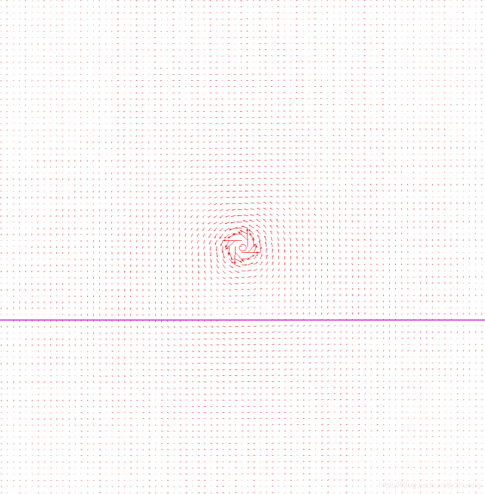
磁感应强度矢量图:
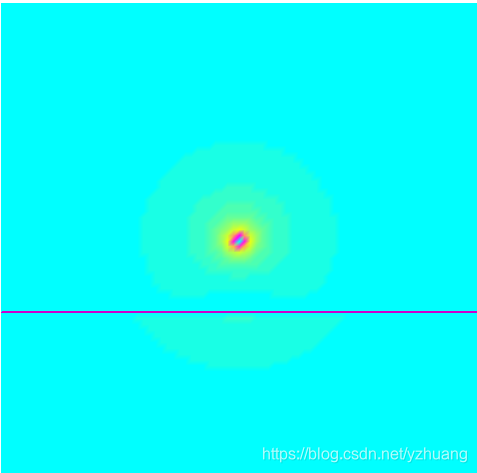
磁场云图:
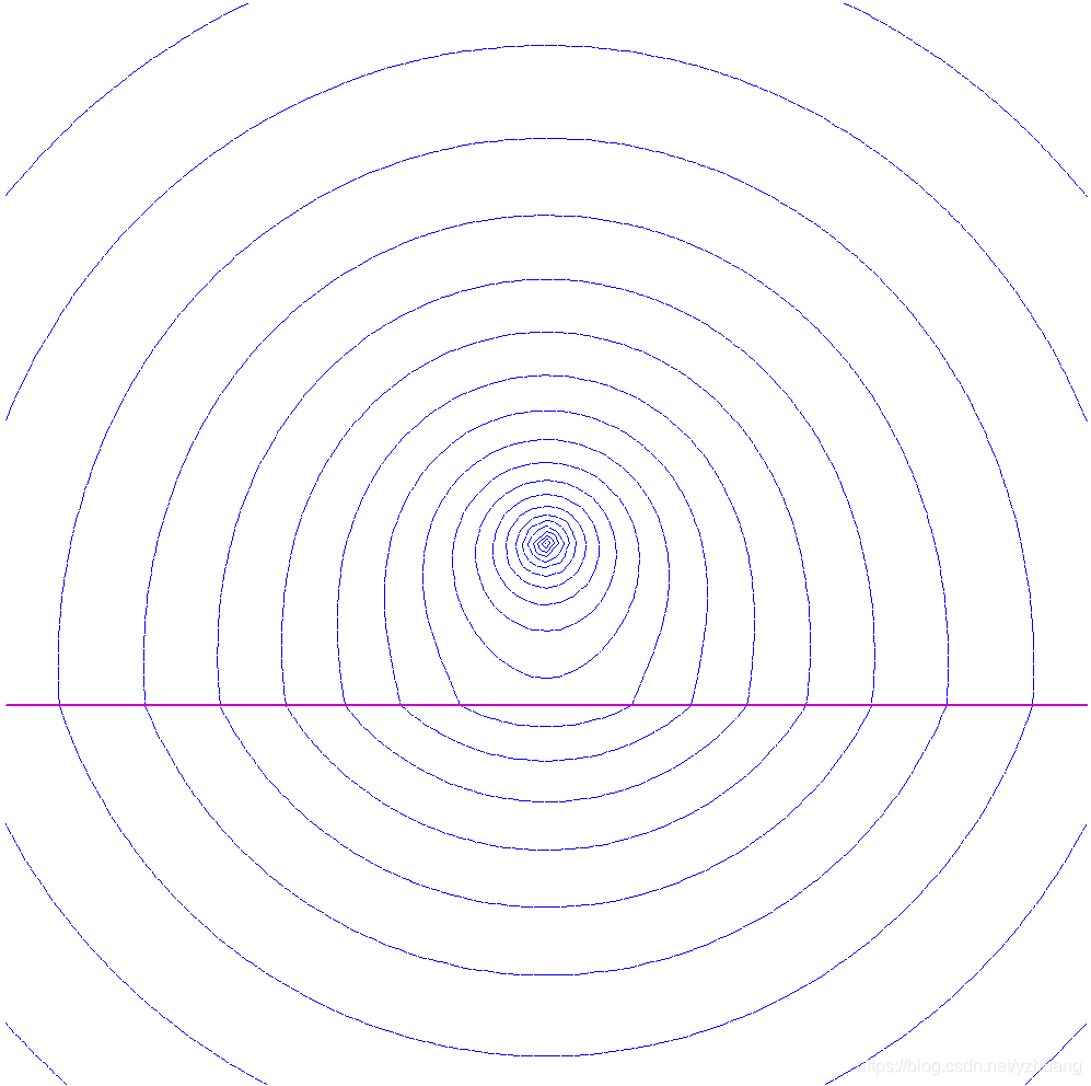
磁场图:
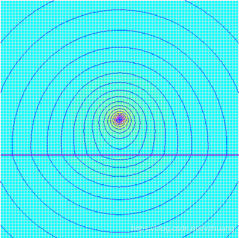
场量合成图:


 2万+
2万+

 被折叠的 条评论
为什么被折叠?
被折叠的 条评论
为什么被折叠?
 到【灌水乐园】发言


