


按键控制LED灯
1.1 按键连接示意图

1.2 代码设计
1.21 设计思路
我们要实现按键控制led,我们需要完成LED和按键驱动代码,但如果把这两部分代码都混在主函数里面,那么代码显得过于杂乱,不容易管理和移植,所以对于这种驱动代码,我们一般采用模块化编程,把它封装起来,单独放在另外的.C和.h文件里。

1.22 程序设计
① LED.h
//用来存放这个驱动程序可以对外提供的函数或变量声明
#ifndef __LED_H//统一模式
#define __LED_H

void LED_Init(void);
void LED1_ON(void);
void LED1_OFF(void);
void LED1_Turn(void);
void LED2_ON(void);
void LED2_OFF(void);
void LED2_Turn(void);

#endif
② LED.C
#include "stm32f10x.h"                  // Device header
//存放点灯主体代码
//LED初始化
void LED_Init(void)
{
    RCC_APB2PeriphClockCmd(RCC_APB2Periph_GPIOA, ENABLE);

    GPIO_InitTypeDef GPIO_InitStructure;
    GPIO_InitStructure.GPIO_Mode = GPIO_Mode_Out_PP;
    GPIO_InitStructure.GPIO_Pin = GPIO_Pin_1 | GPIO_Pin_2;
    GPIO_InitStructure.GPIO_Speed = GPIO_Speed_50MHz;
    GPIO_Init(GPIOA, &GPIO_InitStructure);
    //不操作LED LED熄灭
    GPIO_SetBits(GPIOA, GPIO_Pin_1 | GPIO_Pin_2);
}
//点亮LED1
void LED1_ON(void)
{
    GPIO_ResetBits(GPIOA, GPIO_Pin_1);
}
//熄灭LED1

void LED1_OFF(void)
{
    GPIO_SetBits(GPIOA, GPIO_Pin_1);
}

void LED1_Turn(void)//端口电平反转
{
    if (GPIO_ReadOutputDataBit(GPIOA, GPIO_Pin_1) == 0)//读取当前端口的输出状态,如果当前输出为0,那么置1
    {
        GPIO_SetBits(GPIOA, GPIO_Pin_1);
    }
    else
    {
        GPIO_ResetBits(GPIOA, GPIO_Pin_1);//否则就置0
    }
}
//点亮LED2
void LED2_ON(void)
{
    GPIO_ResetBits(GPIOA, GPIO_Pin_2);
}
//熄灭LED2
void LED2_OFF(void)
{
    GPIO_SetBits(GPIOA, GPIO_Pin_2);
}

void LED2_Turn(void)
{
    if (GPIO_ReadOutputDataBit(GPIOA, GPIO_Pin_2) == 0)
    {
        GPIO_SetBits(GPIOA, GPIO_Pin_2);
    }
    else
    {
        GPIO_ResetBits(GPIOA, GPIO_Pin_2);
    }
}
③ Key.h
#ifndef __KEY_H
#define __KEY_H

void Key_Init(void);
uint8_t Key_GetNum(void);

#endif
④ Key.c
#include "stm32f10x.h"                  // Device header
#include "Delay.h"
//按键初始化
void Key_Init(void)
{
    RCC_APB2PeriphClockCmd(RCC_APB2Periph_GPIOB, ENABLE);

    GPIO_InitTypeDef GPIO_InitStructure;
    GPIO_InitStructure.GPIO_Mode = GPIO_Mode_IPU;//上拉输入
    GPIO_InitStructure.GPIO_Pin = GPIO_Pin_1 | GPIO_Pin_11;//按键接在PB1和PB11口上
    GPIO_InitStructure.GPIO_Speed = GPIO_Speed_50MHz;
    GPIO_Init(GPIOB, &GPIO_InitStructure);
}
//读取按键函数
uint8_t Key_GetNum(void)
{
    uint8_t KeyNum = 0;
    if (GPIO_ReadInputDataBit(GPIOB, GPIO_Pin_1) == 0)//如果读取PB1端口值==0,代表按下按键
    {
        Delay_ms(20);//按键消抖
        while (GPIO_ReadInputDataBit(GPIOB, GPIO_Pin_1) == 0);//检测按键是否松手
        Delay_ms(20);
        KeyNum = 1;//传递出键码1
    }
    if (GPIO_ReadInputDataBit(GPIOB, GPIO_Pin_11) == 0)
    {
        Delay_ms(20);
        while (GPIO_ReadInputDataBit(GPIOB, GPIO_Pin_11) == 0);
        Delay_ms(20);
        KeyNum = 2;
    }

    return KeyNum;
}
⑤ main.c
#include "stm32f10x.h"                  // Device header
#include "Delay.h"
#include "LED.h"
#include "Key.h"
uint8_t KeyNum;

int main(void)
{
    LED_Init();//LED初始化
    Key_Init();

    while (1)
    {
        KeyNum = Key_GetNum();
        if (KeyNum == 1)//按键1按下
        {
            LED1_Turn();
        }
        if (KeyNum == 2)
        {
            LED2_Turn();
        }
    }
}
2. 光敏传感器控制蜂鸣器
2.1 电路连接示意图
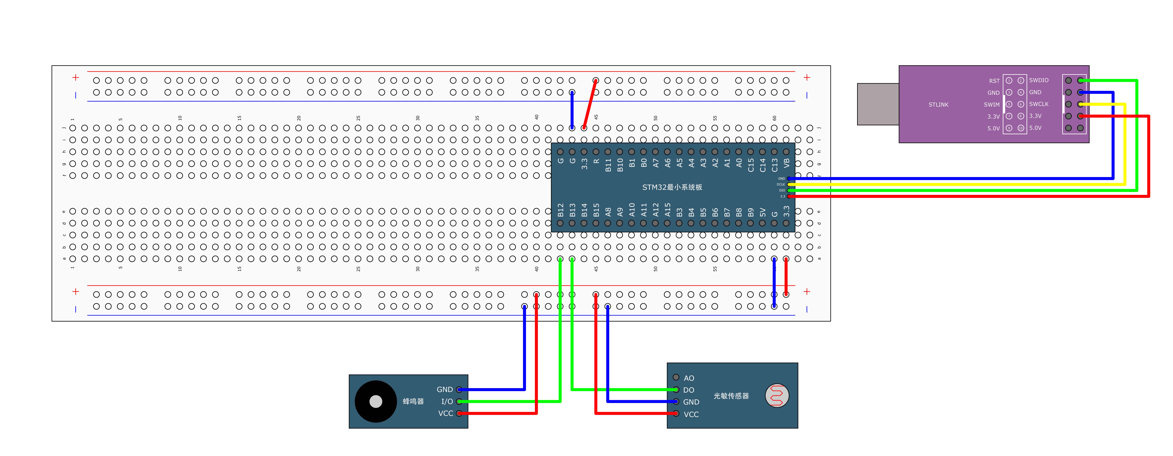
蜂鸣器:VCC GND接电源,控制脚为12号口。
光敏传感器:VCC GND 接电源,DO数字输出端,接P13号口。。
2.2 代码设计
2.21 设计思路
当我们遮蔽光线时,输出指示灯灭,输出高电平,此时蜂鸣器发出声响。接触光线时,输出指示灯亮,输出低电平,蜂鸣器不响。
2.22 程序设计
① Buzzer.h
#ifndef __BUZZER_H
#define __BUZZER_H

void Buzzer_Init(void);
void Buzzer_ON(void);
void Buzzer_OFF(void);
void Buzzer_Turn(void);

#endif
② Buzzer.c
#include "stm32f10x.h"                  // Device header

void Buzzer_Init(void)
{
    RCC_APB2PeriphClockCmd(RCC_APB2Periph_GPIOB, ENABLE);

    GPIO_InitTypeDef GPIO_InitStructure;
    GPIO_InitStructure.GPIO_Mode = GPIO_Mode_Out_PP;
    GPIO_InitStructure.GPIO_Pin = GPIO_Pin_12;//P12口
    GPIO_InitStructure.GPIO_Speed = GPIO_Speed_50MHz;
    GPIO_Init(GPIOB, &GPIO_InitStructure);

    GPIO_SetBits(GPIOB, GPIO_Pin_12);
}
//蜂鸣器打开
void Buzzer_ON(void)
{
    GPIO_ResetBits(GPIOB, GPIO_Pin_12);
}
//蜂鸣器关闭
void Buzzer_OFF(void)
{
    GPIO_SetBits(GPIOB, GPIO_Pin_12);
}
//如果蜂鸣器时打开的,那么将关闭蜂鸣器,如果蜂鸣器关闭,那么将打开蜂鸣器
void Buzzer_Turn(void)
{
    if (GPIO_ReadOutputDataBit(GPIOB, GPIO_Pin_12) == 0)
    {
        GPIO_SetBits(GPIOB, GPIO_Pin_12);
    }
    else
    {
        GPIO_ResetBits(GPIOB, GPIO_Pin_12);
    }
}
③ LightSensor.h
#ifndef __LIGHT_SENSOR_H
#define __LIGHT_SENSOR_H

void LightSensor_Init(void);
uint8_t LightSensor_Get(void);

#endif
④ LightSensor.c
#include "stm32f10x.h"                  // Device header

void LightSensor_Init(void)
{
    RCC_APB2PeriphClockCmd(RCC_APB2Periph_GPIOB, ENABLE);

    GPIO_InitTypeDef GPIO_InitStructure;
    GPIO_InitStructure.GPIO_Mode = GPIO_Mode_IPU;//上拉输入
    GPIO_InitStructure.GPIO_Pin = GPIO_Pin_13;//P13口
    GPIO_InitStructure.GPIO_Speed = GPIO_Speed_50MHz;
    GPIO_Init(GPIOB, &GPIO_InitStructure);
}

uint8_t LightSensor_Get(void)
{
    return GPIO_ReadInputDataBit(GPIOB, GPIO_Pin_13);//读取输入寄存器13号端口的输入值
}
⑤ main.c
#include "stm32f10x.h"                  // Device header
#include "Delay.h"
#include "Buzzer.h"
#include "LightSensor.h"

int main(void)
{
    Buzzer_Init();
    LightSensor_Init();

    while (1)
    {
        if (LightSensor_Get() == 1)//遮蔽光线
        {
            Buzzer_ON();//蜂鸣器鸣叫
        }
        else
        {
            Buzzer_OFF();//蜂鸣器关闭
        }
    }
}
3. 总结 GPIO使用方法
① 初始化时钟
② 定义结构体
③ 赋值结构体
④ 使用GPIO_Init函数,将指定的GPIO外设初始化好


 1003
1003


 被折叠的 条评论
为什么被折叠?
被折叠的 条评论
为什么被折叠?
 到【灌水乐园】发言


