


Kinect Fusion
Kinect for Windows 1.7, 1.8 2代的fusion
What is Kinect Fusion?
KinectFusion provides 3D object scanning and model creation using a Kinect for Windows sensor. The user can paint a scene with the Kinect camera and simultaneously see, and interact with, a detailed 3D model of the scene. Kinect Fusion can be run at interactive rates on supported GPUs, and can run at non-interactive rates on a variety of hardware. Running at non-interactive rates may allow larger volume reconstructions.
Figure 1. Kinect Fusion in action, taking the depth image from the Kinect camera with lots of missing data and within a few seconds producing a realistic smooth 3D reconstruction of a static scene by moving the Kinect sensor around. From this, a point cloud or a 3D mesh can be produced.
.png")
Getting Started (Important!)
- Ensure you have compatible hardware (see Tech Specs section below).
- Download and install the latest graphics display drivers for your GPU.
Tech Specs
Kinect Fusion can process data either on a DirectX 11 compatible GPU with C++ AMP, or on the CPU, by setting the reconstruction processor type during reconstruction volume creation. The CPU processor is best suited to offline processing as only modern DirectX 11 GPUs will enable real-time and interactive frame rates during reconstruction.
Minimum Hardware Requirements for GPU based reconstruction
.gif") Important Important |
|---|
| The minimum hardware requirement for GPU based reconstruction is a DirectX 11 compatible graphics card. Kinect FusionWILL NOT RUN on hardware that does not meet this requirement. |
The minimum hardware requirement for video cards has not been specifically tested for Kinect Fusion 1.8. Kinect Fusion 1.7 has been tested on the NVidia GeForce GTX560 and the AMD Radeon 6950. These cards, or higher end cards from the same product lines, are expected to be able to run at interactive rates.
Recommended Hardware
Desktop PC with 3GHz (or better) multi-core processor and a graphics card with 2GB or more of dedicated on-board memory. Kinect Fusion has been tested for high-end scenarios on a NVidia GeForce GTX680 and AMD Radeon HD 7850.
Note: It is possible to use Kinect Fusion on laptop class DirectX11 GPU hardware, but this typically runs significantly slower than desktop-class hardware. In general, aim to process at the same frame rate as the Kinect sensor (30fps) to enable the most robust camera pose tracking.
How does Kinect Fusion work?
The Kinect Fusion system reconstructs a single dense surface model with smooth surfaces by integrating the depth data from Kinect over time from multiple viewpoints. The camera pose is tracked as the sensor is moved (its location and orientation) and because we now know each frame's pose and how it relates to the others, these multiple viewpoints of the objects or environment can be fused (averaged) together into a single reconstruction voxel volume. Think of a large virtual cube in space (the reconstruction volume), located around your scene in the real world, and depth data (i.e. measurements of where the surfaces are) are put (integrated) into this as the sensor is moved around.
Processing Pipeline
As shown in Figure 2, the Kinect Fusion processing pipeline involves several steps to go from the raw depth to a 3D reconstruction:
Figure 2. Kinect Fusion Pipeline
.png")
- The first stage is depth map conversion. This takes the raw depth from Kinect and converts it into floating point depth in meters, followed by a optional conversion to an oriented point cloud which consists of 3D points/vertices in the camera coordinate system, and the surface normals (orientation of the surface) at these points for use with the AlignPointClouds function.
- The second stage calculates the global/world camera pose (its location and orientation) and tracks this pose as the sensor moves in each frame using an iterative alignment algorithm, so the system always knows the current sensor pose relative to the initial starting frame. There are two algorithms in Kinect Fusion. The first is NuiFusionAlignPointClouds which can either be used to align point clouds calculated from the reconstruction with new incoming point clouds from the Kinect camera depth, or standalone (for example, to align two separate cameras viewing the same scene). The second is AlignDepthToReconstruction which provides more accurate camera tracking results when working with a reconstruction volume, however, this may be less robust to objects which move in a scene. If tracking breaks in this scenario, re-align the camera with the last tracked pose and tracking should typically continue.
- The third stage is fusing (or “integration”) of the depth data from the known sensor pose into a single volumetric representation of the space around the camera. This integration of the depth data is performed per-frame, continuously, with a running average to reduce noise, yet handle some dynamic change in the scene (such as small objects being removed or added). As a moving sensor sees a surface from slightly different viewpoints, any gaps or holes where depth data is not present in the original Kinect image can also be filled in (e.g. you can move the sensor around an object to fill in the rear of the object) and surfaces are continuously refined with newer high resolution data as the camera approaches the surface more closely.
- The reconstruction volume can be raycast from a sensor pose (which is typically, but not limited to, the current Kinect sensor pose), and this resultant point cloud can be shaded for a rendered visible image of the 3D reconstruction volume.
Typical volume sizes that can be scanned are up to around 8m^3. Typical real-world voxel resolutions can be up to around 1-2mm per voxel. However, it is not possible to have both of these simultaneously – see the Reconstruction Volume section below.
Interested in the research behind Kinect Fusion, or more technical detail about the algorithms? See the Microsoft Research Kinect Fusion project page for publications and a video.
Tracking
Kinect Fusion tracking uses only the depth stream from the Kinect sensor. Tracking relies on there being enough variation in the depth in each frame so that it can match up what it sees between frames and calculate the pose difference. If you point the Kinect at a single planar wall, or a mostly planar scene, there will not be enough depth variation for tracking to succeed. Cluttered scenes work the best, so if you are trying to scan an environment, try scattering some objects around if the tracking is problematic.
There are two tracking algorithms implemented in Kinect Fusion – the AlignDepthFloatToReconstruction function and AlignPointClouds function. It is possible to use either for camera pose tracking, however, if you are creating a reconstruction volume the AlignDepthFloatToReconstruction function will likely perform more accurate tracking. In contrast, the AlignPointClouds function can also be used standalone, without a reconstruction volume to align two point clouds - see the interface comments for more information on standalone use. Note that internally the high-level ProcessFrame function in the INuiFusionReconstruction interface uses AlignDepthFloatToReconstruction.
The AlignPointClouds tracking algorithm optionally outputs an ARGB visible image of the camera tracking algorithm alignment results, currently color-coded by per-pixel algorithm output. This may be used as input to additional vision algorithms such as object segmentation. Values vary depending on whether the pixel was a valid pixel used in tracking (inlier) or failed in different tests (outlier). 0xff000000 indicates an invalid input vertex (e.g. from 0 input depth), or one where no correspondances occur between point cloud images. Outlier vertices rejected due to too large a distance betweeen vertices are coded as 0xff008000. Outlier vertices rejected due to to large a difference in normal angle between point clouds are coded as 0xff800000. Inliers are color shaded depending on the residual energy at that point, with more saturated colors indicating more discrepancy between vertices and less saturated colors (i.e. more white) representing less discrepancy, or less information at that pixel. In good tracking the majority of pixels will appear white, with typically small amounts of red and blue around some objects. If you see large amounts of red, blue or green across the whole image, then this indicates tracking is likely lost, or there is drift in the camera pose. Resetting the reconstruction will also reset the tracking here.
The AlignDepthFloatToReconstruction tracking algorithm optionally outputs a an image of type NUI_FUSION_IMAGE_TYPE_FLOAT of the camera tracking algorithm alignment results. The image describes how well each depth pixel aligns with the reconstruction model. This may be processed to create a color rendering, or may be used as input to additional vision algorithms such as object segmentation. These residual values are normalized -1 to 1 and represent the alignment cost/energy for each pixel. Larger magnitude values (either positive or negative) represent more discrepancy, and lower values represent less discrepancy or less information at that pixel. Note that if valid depth exists, but no reconstruction model exists behind the depth pixels, 0 values indicating perfect alignment will be returned for that area. In contrast, where no valid depth occurs 1 values will always be returned.
Constraints on Tracking
Kinect Fusion depends on depth variation in the scene to perform its camera tracking. Scenes must have sufficient depth variation in view (and in the model) to be able to track successfully. Small, slow movement in both translation and rotation are best for maintaining stable tracking. Dropped frames can adversely affect tracking, as a dropped frame can effectively lead to twice the translational and rotational movement between processed frames. When using AlignDepthFloatToReconstruction it is typically possible to guide the user to realign the camera with the last tracked position and orientation and resume tracking.
Reconstruction Volume
The reconstruction volume is made up of small cubes in space, which are generally referred to as Voxels. You can specify the size of the volume on creation by passing a NUI_FUSION_RECONSTRUCTION_PARAMETERS structure to the NuiFusionCreateReconstruction function. The number of voxels that can be created depends on the amount of memory available to be allocated on your reconstruction device, and typically up to around 640x640x640 = 262144000 voxels can be created in total on devices with 1.5GB of memory or more. The aspect ratio of this volume can be arbitrary; however, you should aim to match the volume voxel dimensions to the shape of the area in the real world you aim to scan.
The voxelsPerMeter member scales the size that 1 voxel represents in the real world, so if you have a cubic 384x384x384 volume this can either represent a 3m cube in the real world if you set the voxelsPerMeter member to 128vpm (as 384/128=3, where each voxel is 3m/384=7.8mm^3), or a 1.5m cube if you set it to 256vpm (384/256=1.5, where each voxel is 1.5m/384 = 3.9mm^3). This combination of voxels in the x,y,z axis and voxels per meter will enable you to specify a volume with different sizes and resolutions, but notice that it is a tradeoff – with a fixed number of voxels that you can create, you cannot create a volume which represents a very large world volume, with a very high resolution.
On GPUs the maximum contiguous memory block that can typically be allocated is around 1GB, which limits the reconstruction resolution to approximately 640^3 (262144000 voxels). Similarly, although CPUs typically have more total memory available than a GPU, heap memory fragmentation may prevent very large GB-sized contiguous memory block allocations.. If you need very high resolution also with a large real world volume size, multiple volumes or multiple devices may be a possible solution.
| Note |
|---|
| If you are doing interactive reconstruction on a GPU, the memory requirement applies to the video memory on that GPU. If you are doing offline reconstruction on a CPU, the memory requirement applies to the main memory of that machine. |
Kinect Fusion Samples
The best way to get started with Kinect Fusion is to first try the samples and then look at their code. There are currently eight samples—three native C++ samples (Kinect Fusion Basics-D2D, Kinect Fusion Color Basics-D2D, and Kinect Fusion Explorer-D2D) and five managed C# samples (KinectFusionBasics-WPF, Kinect Fusion Color Basics-WPF, Kinect Fusion Explorer-WPF, Kinect Fusion Explorer Multi-Static Cameras-WPF, and Kinect Fusion Head Scanning-WPF). The basic samples demonstrate the fastest way to get started and minimum code required for Kinect Fusion operation, whereas the Explorer samples expose many of the API parameters as controls in the sample, and allow more exploration of the Fusion capabilities.
Basic Sample: KinectFusionBasics-D2D, KinectFusionBasics-WPF
The basic samples provide a minimal UI, consisting of a grayscale shaded visualization of the reconstruction, a Kinect near mode toggle and reset reconstruction button. All other parameters, including the reconstruction size are set in the code. The basic samples call the ProcessFrame function in the INuiFusionReconstruction interface which encapsulates the camera tracking (AlignDepthFloatToReconstruction) and the data integration step (IntegrateFrame) in one function call to be easier to call and more efficient as all processing takes place on the GPU without upload and readback for the individual steps as would occur when calling separately. Here, the reconstruction is only updated if the camera tracking is successful.
Please note that for environment scanning cluttered scenes enable the best camera tracking – add objects to scenes which are mostly planar. In order to extract a mesh of a particular scene or object in a static scene, these objects can be removed later manually using 3rd party mesh processing tools.
Figure 3. Kinect Fusion Basics Applications scanning desktops (left – D2D, right – WPF)
.png")
- First ensure your machine meets the minimum specifications (see above), then start the application and you should see a window similar to that in Figure 3.
- Point the sensor at a scene, such as a desktop, and start the application. You should see a representation of the desktop appear in the Kinect Fusion sample image. Currently in the sample the resolution is hardcoded in the constructor to 512x384x512 voxels, with 256 voxels per meter (which is a 2m wide x 1.5 high x 2m deep reconstruction volume).
- Press the reset button if the sensor loses track (see status bar at the bottom of the window for lost track messages).
Basic Sample: Kinect Fusion Color Basics-D2D, Kinect Fusion Color Basics-WPF
The basic color samples demonstrate the basic use of the Kinect Fusion APIs for 3D reconstruction with the option of using color. This sample is conceptually similar to the regular basic samples, but use the parallel color reconstruction APIs. There is an inherent tradeoff in using the color APIs, as the storage of the color data in the reconstruction volume has a corresponding decrease (roughly half) in the maximum volume size that it is possible to construct on a graphics card. In addition, using these APIs and integrating color data will take an additional run-time cost which will lower the observed framerate on some graphics cards.
Figure 4. Kinect Fusion Color Basics samples (left – D2D, right – WPF)
.png")
Advanced Sample: KinectFusionExplorer-D2D, KinectFusionExplorer-WPF
The Explorer UI provides more configurability over the Kinect Fusion parameters, and an ability to perform meshing to create a 3D model.
Figure 5. Kinect Fusion Explorer samples scanning a female head model, using 640 voxels^3, with 512 voxels per meter, which is a 1.25m^3 reconstruction volume (left – D2D, right – WPF)
.png")
- First ensure your machine meets the minimum specifications (see above), then start the application and you should see a window similar to that in Figure 4.
- The images in the window are: raw Kinect Depth at top right, Camera Tracking results at bottom right (see Camera Tracking section above), and the main raycast and shaded view into the reconstruction volume from the camera pose in the large image on the left.
- Point the sensor at a scene, such as a desktop, and start the application. You should see a representation of the desktop appear in the Kinect Fusion sample image. Currently in the sample the resolution starts at 512x384x512 voxels, with 256 voxels per meter (which is a 2m wide x 1.5 high x 2m deep reconstruction volume).
- Press the reset button (shown below in Figure 5) if the sensor loses track (see status bar at the bottom of the window for lost track messages).
Figure 6. Depth Threshold Sliders, Reset Button, Create Mesh Button, and other configuration in Kinect Fusion Explorer-D2D
.png")
- Change the depth threshold parameters by moving the depth threshold sliders shown at the bottom of Figure 5. Note how this will clip the depth image in the top right corner. Kinect Fusion requires depth to work, so you need to have valid depth within the region of the reconstruction volume. The sliders start out at minimum 0.35m (near the minimum Kinect sensing distance), and 8m (near the maximum Kinect sensing distance) and can be used for things such as background or foreground removal.
- Try playing with the additional configuration boxes, such as “Display Surface Normals”, “Near Mode” and “Mirror Depth”. Note mirroring depth will reset the reconstruction. “Pause Integration” will stop the reconstruction volume integrating depth data, and is useful if you have fully reconstructed your scene and now only want to track the camera pose, rather than update the scene in the volume (it will also run faster without integration).
Figure 7. Reconstruction Volume Settings in Kinect Fusion Explorer-D2D
.png")
- The Reconstruction volume settings visible in Figure 6 enable you to change the real world size and shape of the reconstruction volume. Try playing around, and see how both the X,Y,Z volume and the voxels per meter affect the size in the real world and the visible resolution of the volume.
- The Maximum Integration weight slider controls the temporal averaging of data into the reconstruction volume – increasing makes the system a higher detailed reconstruction, but one which takes longer to average and does not adapt to change. Decreasing it makes the volume respond faster to change in the depth (e.g. objects moving), but is noisier overall.
- Click the “Create Mesh” button in Figure 6. The meshes output by the Kinect Fusion Explorer sample are the very first step to 3D printing a replica of objects and scenes you scan. Note that most 3D printers require meshes to be closed and watertight, without holes to be able to print. Typically the steps required for 3D printing involve manual cleaning/removal of extraneous geometry then insertion of 3D geometry to close holes. Some popular 3D design and editing, or CAD software packages can perform hole filling automatically. We recommend using the binary STL mesh file output when your scan is a high resolution or the intended target is a 3D printer, as the file size is smaller than the ASCII format .obj.
Note
Note, STL is a unitless format, and different mesh applications interpret the positions as being in different units. In our sample, we assume each unit is 1 Meter.
Advanced Sample: Kinect Fusion Explorer Multi Static Cameras-WPF
The multiple static cameras sample demonstrates how to integrate multiple static Kinect cameras into the same reconstruction volume, given user-defined transformations for each camera. A new third-person view and basic WPF graphics are provided to allow users to visually explore a reconstruction scene during setup and capture. To control the virtual camera, left-click and drag to rotate, right-click and drag to translate, and use the mouse wheel to zoom. The graphics show the reconstruction extent in green and individual camera frustums in yellow. Both the reconstruction volume origin and the WPF graphics origin are displayed as short red, green, and blue orthogonal axis lines that correspond to the x-, y-, and z-axes, respectively.
Advanced Sample: Kinect Fusion Head Scanning-WPF
The head scanning sample demonstrates how to leverage a combination of Kinect Fusion and Face Tracking to scan high resolution models of faces and heads.
Moving versus Static Sensor
Conceptually, a moving sensor with a static scene (e.g. environment scanning), and a static sensor with a moving scene (e.g. object scanning) are equivalent. Kinect Fusion supports both, but in general, the moving sensor with static scene scenario is much more robust as there is a larger amount of varied data for camera tracking.
For object scanning with a static sensor, make sure the object has enough depth variation and covers a large enough area of the Kinect image without getting too close and having depth return 0 (this typically limits the minimum size of objects you can reconstruct). Try to isolate the object from the environment using the depth thresholds in the KinectFusionExplorer-D2D sample, or when calling NuiFusionDepthToDepthFloatFrame in your own code. Optionally mask the environment around the object from the reconstruction by setting pixels around the object in the input depth image to 0 depth. For scanning people, the playermask can potentially be used to perform a rough segmentation – see the GreenScreen Kinect For Windows sample applications.
Multiple GPUs, Threads and Reconstruction Volumes
Multiple GPUs can be used by Kinect Fusion, however, each must have its own reconstruction volume(s), as an individual volume can only exist on one GPU. It is recommended your application is multithreaded for this and each thread specifies a device index when calling NuiFusionCreateReconstruction.
Multiple volumes can also exist on the same GPU – just create multiple instances of INuiFusionReconstruction. Individual volumes can also be used in multi-threaded environments, however, note that the volume related functions will block if a call is in progress from another thread.
Tips
- Add clutter at different depths to scenes when environment scanning to improve problematic tracking.
- Mask out background pixels to only focus on the object when scanning small objects with a static sensor.
- Don’t move the sensor too fast or jerkily.
- Don’t get too close to objects and surfaces you are scanning – monitor the Kinect depth image.
- As we only rely on depth, illumination is not an issue (it even works in the dark).
- Some objects may not appear in the depth image as they absorb or reflect too much IR light – try scanning from different angles (especially perpendicular to the surface) to reconstruct.
- If limited processing power is available, prefer smaller voxel resolution volumes and faster/better tracking over high resolution volumes (slow) and worse tracking.
- If surfaces do not disappear from the volume when something moves, make sure the sensor sees valid depth behind it – if there is 0 depth in the image, it does not know that it can remove these surfaces, as it is also possible something may also be very close to the sensor inside the minimum sensing distance occluding the view.
社区附加资源
添加Thanks
版权声明:本文为博主原创文章,未经博主允许不得转载。
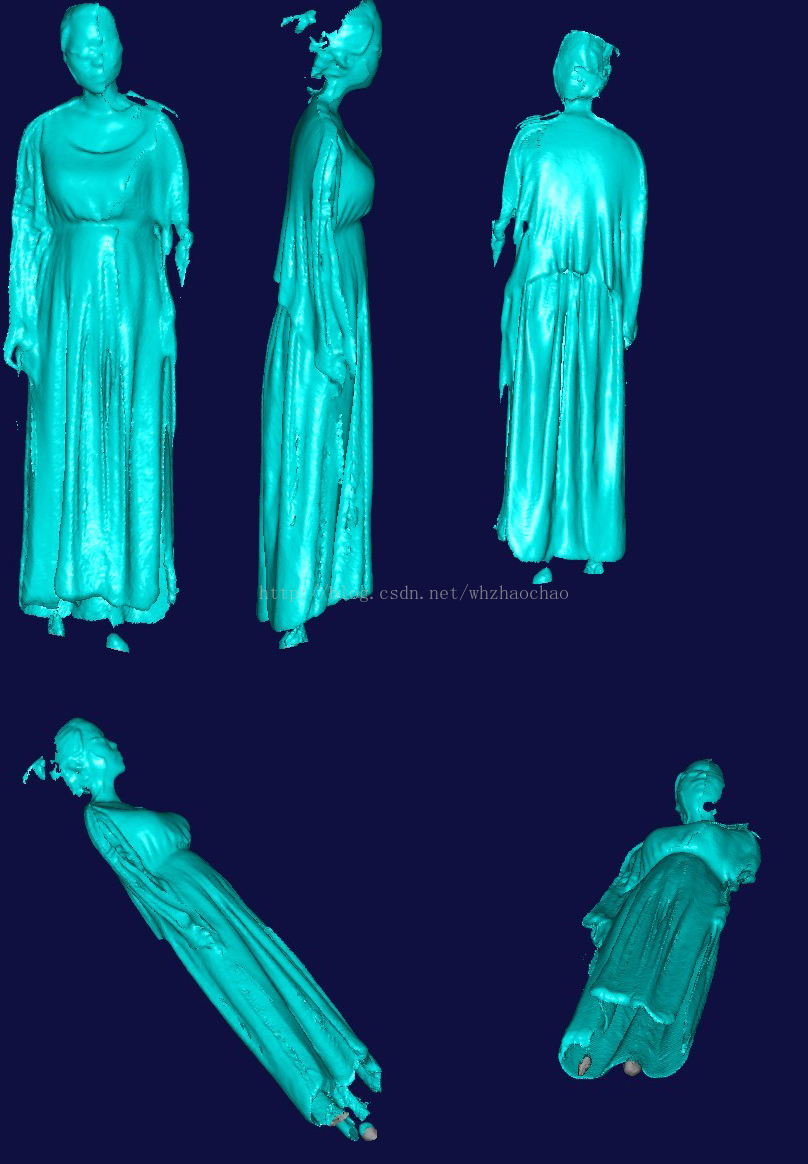
1.先看3D扫描效果图
2.环境要求
Kinect Fusion官网http://msdn.microsoft.com/en-us/library/dn188670.aspx
CPU 3GHz以上多核处理器
显卡2G以上
支持DirectX 11
在 NVidia GeForce GTX680和AMD Radeon HD 7850上可以运行
3.我的运行环境
4.下载Kinect SDKhttp://www.microsoft.com/en-us/download/details.aspx?id=36996
和开发工具http://www.microsoft.com/en-us/download/details.aspx?id=36998
注意要下载Kinect for Windows SDK v1.7 和Kinect for Windows Developer Toolkit v1.7 以上版本,因为只有在1.7之后才加入了Fusion功能
5.安装Kinect SDK和 Developer Toolkit,注意先安装Kinect SDK后安装 Developer Toolkit
6.硬件和软件装备就绪后打开Kinect from Windows Devloper Toolkit V1.7.0可看到如下效果
7.然后点Kinect Fusion Explorer-D2D后面的Run如果没有问题就可以看到如下3D扫描窗口
8.如果这步成功接下来就可以3D扫描了,Min和Max是深度调节,调节深度使目标为于这个深度范围,然后点Reset Reconstruction初使化扫描。有两种方法可以扫描,一种是Kinect绕目标物体转,一种是物体自转,完成扫描后点Create Mesh生成3D模型文件,格式可以选择STL和OBJ,保存后用第三方软件(STL VIEWER、eDrawingsFullEnglish、imageware、3DMAX )STLVIEWER下载地址http://download.csdn.net/detail/whzhaochao/5965289看3D模型效果如下


 1794
1794

 被折叠的 条评论
为什么被折叠?
被折叠的 条评论
为什么被折叠?
 到【灌水乐园】发言


