


一、材料准备
1、STM32F103C8T6最小系统板+电脑(Keil5软件)
2、MCP4725模块开发板(12位DAC、I2C通讯协议)
3、自己焊接的电压转电流电路及5V转发电路
二、电路仿真测试
1、电路仿真就不放换算公式,直接上电路图。
R8为负载阻值。R8=51Ω;

R8为负载阻值。R8=500Ω;
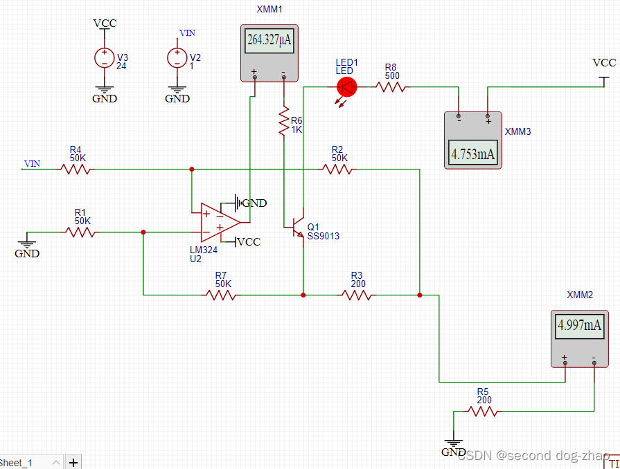
可以明确看出在1V的输入电压的情况下,负载阻值增加近9倍,电流变化不足0.01mA。
5VDC-DC电路十分常见,电路图如下。

三、MCP4725和STM32通讯连接
1、本次使用软I2C编写代码,所以先制作了I2C的采集和响应代码
#include "stm32f10x.h"                  // Device header
#include "delay.h"
#include "stdio.h"
#include "I2C_TypeDefStructure.h"


void I2CW_SCL(MyI2C_TypeDef *GPIO_I2C,uint8_t X)
{
	GPIO_WriteBit(GPIO_I2C->GPIOX,GPIO_I2C->GPIO_Pin_SCL,(BitAction)X);
	Delay_us(10);
}
void I2CW_SDA(MyI2C_TypeDef *GPIO_I2C,uint8_t X)
{
	GPIO_WriteBit(GPIO_I2C->GPIOX,GPIO_I2C->GPIO_Pin_SDA,(BitAction)X);
	Delay_us(10);
}
uint8_t I2CR_SDA(MyI2C_TypeDef *GPIO_I2C)
{
	uint8_t X;
	X = GPIO_ReadInputDataBit(GPIO_I2C->GPIOX,GPIO_I2C->GPIO_Pin_SDA);
	Delay_us(10);
	return X;
}

void MyI2C_Init(MyI2C_TypeDef *GPIO_I2C)
{

	RCC_APB2PeriphClockCmd(RCC_APB2Periph_GPIOB,ENABLE);

	GPIO_InitTypeDef GPIO_InitStructure;
	GPIO_InitStructure.GPIO_Mode=GPIO_Mode_Out_OD;
	GPIO_InitStructure.GPIO_Pin=GPIO_I2C->GPIO_Pin_SDA|GPIO_I2C->GPIO_Pin_SCL;
	GPIO_InitStructure.GPIO_Speed=GPIO_Speed_50MHz;
	GPIO_Init(GPIO_I2C->GPIOX,&GPIO_InitStructure);

	GPIO_SetBits(GPIO_I2C->GPIOX,GPIO_I2C->GPIO_Pin_SCL|GPIO_I2C->GPIO_Pin_SDA);
}


void MyI2C_Start(MyI2C_TypeDef *GPIO_I2C)
{
	I2CW_SDA(GPIO_I2C,1);
	I2CW_SCL(GPIO_I2C,1);
	I2CW_SDA(GPIO_I2C,0);
	I2CW_SCL(GPIO_I2C,0);
}

void MyI2C_Stop(MyI2C_TypeDef *GPIO_I2C)
{
	I2CW_SDA(GPIO_I2C,0);
	I2CW_SCL(GPIO_I2C,1);
	I2CW_SDA(GPIO_I2C,1);

}
void MyI2C_SendByte(MyI2C_TypeDef *GPIO_I2C,uint8_t Byte)
{
	for(uint8_t i=0;i < 8;i++)
	{
	I2CW_SDA(GPIO_I2C,Byte & (0x80>>i));
	I2CW_SCL(GPIO_I2C,1);
	I2CW_SCL(GPIO_I2C,0);
	}
}

uint8_t MyI2C_ReceiveByte(MyI2C_TypeDef *GPIO_I2C)
{
	uint8_t Byte=0x00;
	I2CW_SDA(GPIO_I2C,1);
	for(uint8_t i=0;i<8;i++)
	{
		I2CW_SCL(GPIO_I2C,1);
		if(I2CR_SDA(GPIO_I2C)==1)
		{
			Byte|=(0x80>>i);
		}
		I2CW_SCL(GPIO_I2C,0);
	}
	return Byte;
}

void MyI2C_SendACK(MyI2C_TypeDef *GPIO_I2C,uint8_t ACK) // 在每一次字节发送数据要有应答,应答的目标是告诉从机下一个时序的开始
{
	I2CW_SDA(GPIO_I2C,ACK);
	I2CW_SCL(GPIO_I2C,1);
	I2CW_SCL(GPIO_I2C,0);
}

uint8_t MyI2C_ReceiveACK(MyI2C_TypeDef *GPIO_I2C)
{
	uint8_t ACK=0x00;
	I2CW_SDA(GPIO_I2C,1);
	I2CW_SCL(GPIO_I2C,1);
	ACK=I2CR_SDA(GPIO_I2C);
	I2CW_SCL(GPIO_I2C,0);
	return ACK;
}
2、MCP4725的驱动时序电路
#include "stm32f10x.h"                  // Device header
#include "MyI2C.h"
#include "I2C_TypeDefStructure.h"


void MCP4725_Init(MyI2C_TypeDef *GPIO_I2C)
{
	MyI2C_Init(GPIO_I2C);
}

void MCP4725_SendDAC(MyI2C_TypeDef *GPIO_I2C,float DAC_Aout,float DAC_ALL)
{
	uint16_t DAC_Byte=(DAC_Aout/DAC_ALL)*4095;
	uint8_t Data_H=((0x0F00&DAC_Byte)>>8);
	uint8_t Data_L=0x00FF&DAC_Byte;
	MyI2C_Start(GPIO_I2C);
	MyI2C_SendByte(GPIO_I2C,0xC0);//Mcp4725设备地址
	MyI2C_ReceiveACK(GPIO_I2C);
	MyI2C_SendByte(GPIO_I2C,Data_H);
	MyI2C_ReceiveACK(GPIO_I2C);
	MyI2C_SendByte(GPIO_I2C,Data_L);
	MyI2C_ReceiveACK(GPIO_I2C);
	MyI2C_Stop(GPIO_I2C);
}
3、最后就是主程序的显示
#include "MCP4725.h"
#include "I2C_TypeDefStructure.h"
void OLED_ShowFloat(uint8_t line,uint8_t Colum,float num,uint8_t Length)
{
	uint32_t GEWEI=0;
	uint32_t XIAOSHU=0;
	GEWEI=num/1;
	OLED_ShowNum(line,Colum,GEWEI,1);
	XIAOSHU=(num-GEWEI)*100;
	OLED_ShowChar(line,Colum+1,'.');
	OLED_ShowNum(line,Colum+3,XIAOSHU,2);
}
int main()
{
	OLED_Init();

	MyI2C_TypeDef MCP4725_1Typedef;
	MCP4725_1Typedef.GPIOX=GPIOA;
	MCP4725_1Typedef.GPIO_Pin_SDA=GPIO_Pin_2;
	MCP4725_1Typedef.GPIO_Pin_SCL=GPIO_Pin_3;


	MCP4725_Init(&MCP4725_1Typedef);

	float a=0.0;
	while(1)
	{

		a =a+0.1;
		OLED_ShowNum(1,1,a,4);
		MCP4725_SendDAC(&MCP4725_1Typedef,a,4.5);
		if(a==4.5)
			a=0.0;
		Delay_ms(500);


	}
}
4、最后就是把STM32系统板,电路供电、型号转换电路进行连接测试了。


 5433
5433


 被折叠的 条评论
为什么被折叠?
被折叠的 条评论
为什么被折叠?
 到【灌水乐园】发言


