


一、DS1302时钟简介
1.与定时器对比
DS1302时钟也称为RTC时钟(Real Time Clock,实时时钟),说到时钟,可能会想到定时器,下表来简单说明一下两者的区别。
| 定时器(Timer) | 实时时钟(RTC) |
| 精度高,可达微秒级 | 精度较低,多为秒级 |
| 计时范围短 | 计时范围长 |
2.开发板所在位置
下面方框里面的是该时钟芯片,左侧的是晶振,晶振的精度也就决定了时钟芯片的精度。

二、 DS1302时钟原理图

1脚对应的VCC2连接到供电VCC,8脚对应的VCC1通常连接为时钟供电的纽扣电池,这两个引脚起到相互补充的作用,当其中一端不供电时,另一端会接替进行供电。确保DS1302时钟芯片实时处在工作状态。这样的时钟芯片在笔记本电脑和手机中都是存在的。
X1,X2连接了外部的时钟晶振,时钟频率是32.768khz,大部分RTC时钟都是这个频率,32.768khz是2的整数次方,也就是说对其进行二分频,最终会得到1Hz的频率,它的精度就是秒级
4脚对应的是GND,与上面的VCC是配套的
右侧的5,6,7是有单片机的三个引脚控制,与单片机进行串行通信的
三、DS1302时钟芯片原理
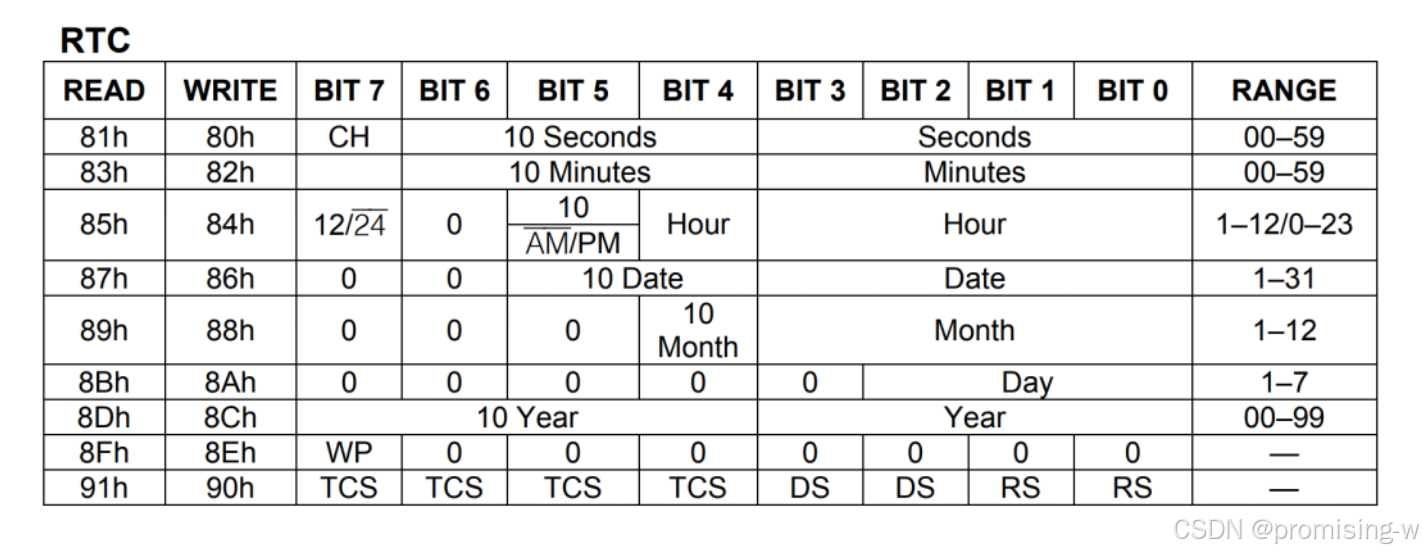
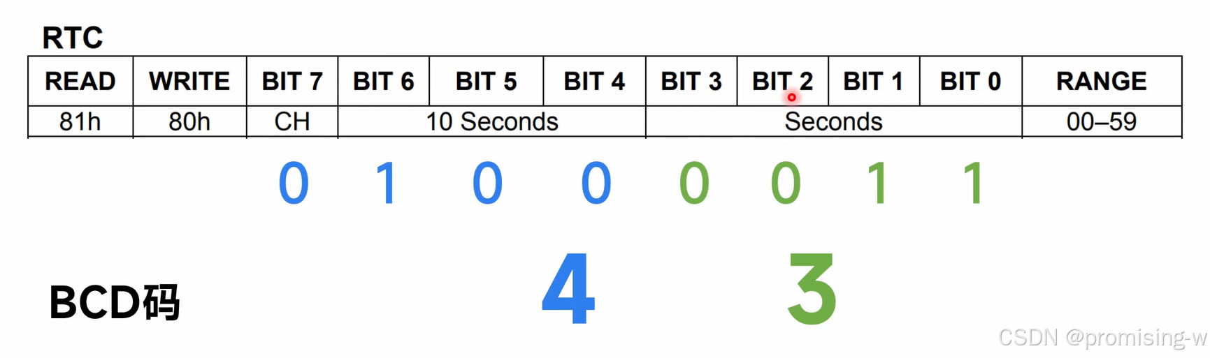
RTC内部是以BCD码进行存储的,BCD码对应的形式如下
下面的几行分别是对分,时,日,月,年的描述
左边第一列是读入地址,第二列是写入地址
WP是写保护,想要写入的时候,先解除写保护(WP=0),然后进行写入,写完后恢复写保护(WP=1),保证不会有别的因素去干扰它
四、DS1302时钟模块代码
该模块需要包含了“intrins.h”,因为用到了_nop_();语句
RTC写入时有写保护,读取时不需要写保护
值得学习的是,对于小时,分钟,秒转换成BCD码的读取和写入的写法
写入
temp =((pucRTC[0]/10)<<4)|(pucRTC[0]%10);//23 0010 0000| 0000 0011
Write_Ds1302_Byte(0x84,temp); 小时
temp =((pucRTC[1]/10)<<4)|(pucRTC[1]%10);
Write_Ds1302_Byte(0x82,temp);分钟
temp =((pucRTC[2]/10)<<4)|(pucRTC[2]%10);
Write_Ds1302_Byte(0x80,temp);秒
读取
temp=Read_Ds1302_Byte(0x85);
pucRTC[0] =(temp>>4)*10+(temp&0x0f);//小时的读取
temp=Read_Ds1302_Byte(0x83);
pucRTC[1] =(temp>>4)*10+(temp&0x0f);//分钟的读取
temp=Read_Ds1302_Byte(0x81);
pucRTC[2] =(temp>>4)*10+(temp&0x0f); //秒的读取
#include "ds1302.h"
#include "intrins.h"//包含_nop_();函数
//
void Write_Ds1302(unsigned  char temp)
{
	unsigned char i;
	for (i=0;i<8;i++)
	{
		SCK = 0;
		SDA = temp&0x01;
		temp>>=1;
		SCK=1;
	}
}

//
void Write_Ds1302_Byte( unsigned char address,unsigned char dat )//第一个是地址,第二个是数据
{
 	RST=0;	_nop_();
 	SCK=0;	_nop_();
 	RST=1; 	_nop_();
 	Write_Ds1302(address);
 	Write_Ds1302(dat);
 	RST=0;
}

//
unsigned char Read_Ds1302_Byte ( unsigned char address )
{
 	unsigned char i,temp=0x00;
 	RST=0;	_nop_();
 	SCK=0;	_nop_();
 	RST=1;	_nop_();
 	Write_Ds1302(address);
 	for (i=0;i<8;i++)
 	{
		SCK=0;
		temp>>=1;
 		if(SDA)
 		temp|=0x80;
 		SCK=1;
	}
 	RST=0;	_nop_();
 	SCK=0;	_nop_();
	SCK=1;	_nop_();
	SDA=0;	_nop_();
	SDA=1;	_nop_();
	return (temp);
}

void Set_RTC(unsigned char *pucRTC)
{
	unsigned char temp;

	Write_Ds1302_Byte(0x8e,0x00);//解除写保护

	temp =((pucRTC[0]/10)<<4)|(pucRTC[0]%10);//23 0010 0000| 0000 0011
	Write_Ds1302_Byte(0x84,temp);

	temp =((pucRTC[1]/10)<<4)|(pucRTC[1]%10);
	Write_Ds1302_Byte(0x82,temp);

	temp =((pucRTC[2]/10)<<4)|(pucRTC[2]%10);
	Write_Ds1302_Byte(0x80,temp);

	Write_Ds1302_Byte(0x8e,0x80);//恢复写保护
}

void Get_RTC(unsigned char *pucRTC)
{
	unsigned char temp;
	temp=Read_Ds1302_Byte(0x85);
	pucRTC[0] =(temp>>4)*10+(temp&0x0f);//小时的读取

	temp=Read_Ds1302_Byte(0x83);
	pucRTC[1] =(temp>>4)*10+(temp&0x0f);

	temp=Read_Ds1302_Byte(0x81);
	pucRTC[2] =(temp>>4)*10+(temp&0x0f);

}
五、主函数代码
#include "STC15F2K60S2.H"
#include "seg.h"
#include "tim.h"
#include "init.h"
#include "ds1302.h"
//RTC
unsigned char pucRTC[3]={23,59,59};
void RTC_Proc(void);
//Seg
unsigned char pucSeg_Buf[12],pucSeg_Code[9],pucSeg_Pos=0;//字符数组以/0结尾,所以要有9位
void Seg_Proc(void);

//Timer
unsigned long ulms =0;
unsigned int uiSeg_Dly=0;
unsigned int uiRTC_Dly=0;
void main(void)
{
	Cls_Peripheral();
	Timer0Init();
	EA=1;
	Set_RTC(pucRTC);

	while(1)
	{
		Seg_Proc();
		RTC_Proc();
	}

}

void Seg_Proc(void)
{
	if(uiSeg_Dly<200)
		return;

	uiSeg_Dly =0;

	sprintf(pucSeg_Buf,"%02d %02d %02d",(unsigned int)pucRTC[0],(unsigned int)pucRTC[1],(unsigned int)pucRTC[2]);//将指定的内容打印到字符数组里
	Seg_Tran(pucSeg_Buf,pucSeg_Code);
}

void RTC_Proc(void)
{
	if(uiRTC_Dly<200)
		return;

	uiRTC_Dly =0;
	Get_RTC(pucRTC);
}

void Time_0(void) interrupt 1
{
	ulms++;
	uiSeg_Dly++;
	uiRTC_Dly++;
	if(ulms % 2==0)
	{
	pucSeg_Pos=(pucSeg_Pos+1)%8;//实现pucSeg_Pos从0-7循环的操作
	Seg_Disp(pucSeg_Code,pucSeg_Pos);
	}
}- 给数码管的输入格式用%02d,这样可以避免当数字为个位数时,没有0导致占位混乱
- 在主函数中需要给RTC时钟提前设定一个时间
- 数码管显示的是以数组形式展示的时间


 4147
4147

 被折叠的 条评论
为什么被折叠?
被折叠的 条评论
为什么被折叠?
 到【灌水乐园】发言


