硬件:STM32F103C8T6、HC-SR04(超声波)、电位调节器、Ky-008(激光)
项目原理: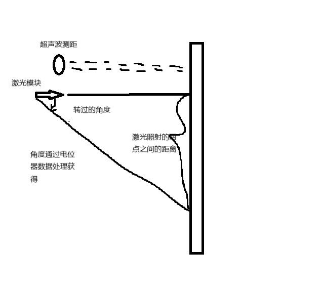
float distance = HC_SR04_GetDistance();//distance就是超声波测距的距离数据,cm
uint16_t Value=ADC_GetValue();//电位器通过ADC,得到的数据
uint16_t angle=270*Value/4096;//270是电位器旋转的角度范围,你们要根据所买电位器角度范围更改
double angle_in_radians = (double)angle * M_PI / 180.0;//C语言中tan()函数的参数为弧度制
double lenth=tan(angle_in_radians)*distance;//结果
代码实现:
HC_SR04.C
#include "HC_SRO4.h"
#include "stm32f10x.h"
#include "DELAY.h"
volatile uint32_t echo_high_time = 0;  // 存储高电平持续时间(微秒)

// 外部中断服务函数(Echo引脚)
void EXTI1_IRQHandler(void) {
    if (EXTI_GetITStatus(EXTI_Line1) != RESET) {
        if (GPIO_ReadInputDataBit(GPIOA, GPIO_Pin_1) == SET) {
            // 上升沿:启动定时器
            TIM_SetCounter(TIM2, 0);
            TIM_Cmd(TIM2, ENABLE);
        } else {
            // 下降沿:停止定时器并记录时间
            echo_high_time = TIM_GetCounter(TIM2);
            TIM_Cmd(TIM2, DISABLE);
        }
        EXTI_ClearITPendingBit(EXTI_Line1);
    }
}

// 初始化HC-SR04
void HC_SR04_Init(void) {
    GPIO_InitTypeDef GPIO_InitStruct;
    NVIC_InitTypeDef NVIC_InitStruct;
    EXTI_InitTypeDef EXTI_InitStruct;
    TIM_TimeBaseInitTypeDef TIM_InitStruct;

    // 1. 使能时钟
    RCC_APB2PeriphClockCmd(RCC_APB2Periph_GPIOA | RCC_APB2Periph_AFIO, ENABLE);
    RCC_APB1PeriphClockCmd(RCC_APB1Periph_TIM2, ENABLE);

    // 2. 配置Trig引脚(PA0)为输出
    GPIO_InitStruct.GPIO_Pin = GPIO_Pin_0;
    GPIO_InitStruct.GPIO_Mode = GPIO_Mode_Out_PP;
    GPIO_InitStruct.GPIO_Speed = GPIO_Speed_50MHz;
    GPIO_Init(GPIOA, &GPIO_InitStruct);

    // 3. 配置Echo引脚(PA1)为输入,并启用外部中断
    GPIO_InitStruct.GPIO_Pin = GPIO_Pin_1;
    GPIO_InitStruct.GPIO_Mode = GPIO_Mode_IPU;  // 上拉输入
    GPIO_Init(GPIOA, &GPIO_InitStruct);

    // 4. 配置外部中断
    GPIO_EXTILineConfig(GPIO_PortSourceGPIOA, GPIO_PinSource1);
    EXTI_InitStruct.EXTI_Line = EXTI_Line1;
    EXTI_InitStruct.EXTI_Mode = EXTI_Mode_Interrupt;
    EXTI_InitStruct.EXTI_Trigger = EXTI_Trigger_Rising_Falling;  // 上升沿和下降沿触发
    EXTI_InitStruct.EXTI_LineCmd = ENABLE;
    EXTI_Init(&EXTI_InitStruct);

    // 5. 配置NVIC
    NVIC_InitStruct.NVIC_IRQChannel = EXTI1_IRQn;
    NVIC_InitStruct.NVIC_IRQChannelPreemptionPriority = 0x0F;
    NVIC_InitStruct.NVIC_IRQChannelSubPriority = 0x0F;
    NVIC_InitStruct.NVIC_IRQChannelCmd = ENABLE;
    NVIC_Init(&NVIC_InitStruct);

    // 6. 配置TIM2(1微秒计数,72MHz/72 = 1MHz)
    TIM_InitStruct.TIM_Prescaler = 72 - 1;  // 分频后时钟1MHz
    TIM_InitStruct.TIM_CounterMode = TIM_CounterMode_Up;
    TIM_InitStruct.TIM_Period = 0xFFFF;      // 最大计数值
    TIM_InitStruct.TIM_ClockDivision = TIM_CKD_DIV1;
    TIM_TimeBaseInit(TIM2, &TIM_InitStruct);
    TIM_Cmd(TIM2, DISABLE);  // 初始状态关闭
}

// 触发测距并返回距离(单位:厘米)
float HC_SR04_GetDistance(void) {
    float distance = 0.0f;

    // 1. 发送10us高电平触发信号
    GPIO_SetBits(GPIOA, GPIO_Pin_0);
    Delay_us(15);  // 需实现微秒级延时(或使用定时器)
    GPIO_ResetBits(GPIOA, GPIO_Pin_0);

    // 2. 等待回波信号(超时处理)
    uint32_t timeout = 1000000;  // 约1秒超时
    while (echo_high_time == 0 && timeout--);

    // 3. 计算距离(时间微秒 * 声速(340m/s) / 2)
    if (echo_high_time > 0) {
        distance = (echo_high_time * 0.0343) / 2.0f;  // 单位:厘米
        echo_high_time = 0;  // 清零标志
    }

    return distance;
}
HC_SR04.H
#ifndef HC_SR04_H
#define HC_SR04_H

#include "stm32f10x.h"


void HC_SR04_Init(void);
float HC_SR04_GetDistance(void);

#endif
adc.c(电位器数据读取)
#include "stm32f10x.h"
void MY_ADC_Init(void)
{
    //开启时钟
    RCC_APB2PeriphClockCmd(RCC_APB2Periph_GPIOA,ENABLE );
    RCC_APB2PeriphClockCmd(RCC_APB2Periph_ADC1,ENABLE );
    //adc预分频,最高14MHz,这里6分频:72/6=12M
    RCC_ADCCLKConfig(RCC_PCLK2_Div6);
    //配置PA2为模拟输入模式
    GPIO_InitTypeDef GPIO_InitStructrue;
    GPIO_InitStructrue.GPIO_Mode=GPIO_Mode_AIN;
    GPIO_InitStructrue.GPIO_Pin=GPIO_Pin_2;
    GPIO_InitStructrue.GPIO_Speed=GPIO_Speed_50MHz;
    GPIO_Init(GPIOA,&GPIO_InitStructrue);
    //选择规则组输入通道
    ADC_RegularChannelConfig(ADC1,ADC_Channel_2,1,ADC_SampleTime_41Cycles5);
    //配置ADC
    ADC_InitTypeDef ADC_InitStructrue;
    ADC_InitStructrue.ADC_ContinuousConvMode=ENABLE;
    ADC_InitStructrue.ADC_DataAlign=ADC_DataAlign_Right;
    ADC_InitStructrue.ADC_ExternalTrigConv=ADC_ExternalTrigConv_None;//触发源
    ADC_InitStructrue.ADC_Mode=ADC_Mode_Independent;
    ADC_InitStructrue.ADC_NbrOfChannel=1;//扫描模式下的通道数目
    ADC_InitStructrue.ADC_ScanConvMode=ENABLE;
    ADC_Init(ADC1,&ADC_InitStructrue);
    //使能adc
    ADC_Cmd(ADC1,ENABLE );
    //校准
    ADC_ResetCalibration(ADC1);
    while (ADC_GetResetCalibrationStatus(ADC1));
    ADC_StartCalibration(ADC1);
    while (ADC_GetCalibrationStatus(ADC1));
}
uint16_t ADC_GetValue(void) {
    // 启动ADC转换
    ADC_SoftwareStartConvCmd(ADC1, ENABLE);
    // 等待转换完成
    while (ADC_GetFlagStatus(ADC1, ADC_FLAG_EOC) == RESET);
    // 读取转换结果
    return ADC_GetConversionValue(ADC1);
}
adc.h
#ifndef adc_H
#define adc_H

#include "stm32f10x.h"
void MY_ADC_Init(void);
uint16_t ADC_GetValue(void);

#endif
ky_008.c(激光)
#include "stm32f10x.h"
void Ky_008_Init(void)
{
    //开启时钟
    RCC_APB2PeriphClockCmd(RCC_APB2Periph_GPIOA,ENABLE );
    //配置PA3为推挽输出模式
    GPIO_InitTypeDef GPIO_InitStructrue;
    GPIO_InitStructrue.GPIO_Mode=GPIO_Mode_Out_PP;
    GPIO_InitStructrue.GPIO_Pin=GPIO_Pin_3;
    GPIO_InitStructrue.GPIO_Speed=GPIO_Speed_50MHz;
    GPIO_Init(GPIOA,&GPIO_InitStructrue);
}
ky_008.h
#ifndef ky_008_H
#define ky_008_H

#include "stm32f10x.h"
void Ky_008_Init(void);

#endif
USART.c
#include "stm32f10x.h"
#include "stdio.h"
//串口初始化函数
void MY_USART_Init(void)
{
    RCC_APB2PeriphClockCmd(RCC_APB2Periph_USART1,ENABLE );
    RCC_APB2PeriphClockCmd(RCC_APB2Periph_GPIOA,ENABLE );
    //PA9,复用推挽输出
    GPIO_InitTypeDef GPIO_UsartTX_Initstruct;
    GPIO_UsartTX_Initstruct.GPIO_Mode=GPIO_Mode_AF_PP;
    GPIO_UsartTX_Initstruct.GPIO_Pin=GPIO_Pin_9;
    GPIO_UsartTX_Initstruct.GPIO_Speed=GPIO_Speed_50MHz;
    GPIO_Init(GPIOA,&GPIO_UsartTX_Initstruct);
    //PA10,浮空输出
    GPIO_InitTypeDef GPIO_UsartRX_Initstruct;
    GPIO_UsartRX_Initstruct.GPIO_Mode=GPIO_Mode_IN_FLOATING;
    GPIO_UsartRX_Initstruct.GPIO_Pin=GPIO_Pin_10;
    GPIO_UsartRX_Initstruct.GPIO_Speed=GPIO_Speed_50MHz;
    GPIO_Init(GPIOA,&GPIO_UsartRX_Initstruct);
    //配置USART参数
    USART_InitTypeDef USART_Initstruct;
    USART_Initstruct.USART_BaudRate=115200;//波特率
    USART_Initstruct.USART_HardwareFlowControl=USART_HardwareFlowControl_None;//流控
    USART_Initstruct.USART_Mode=USART_Mode_Tx|USART_Mode_Rx;//发送或者接收模式(可以都选)
    USART_Initstruct.USART_Parity=USART_Parity_No;//校验
    USART_Initstruct.USART_StopBits=USART_StopBits_1;//停止位
    USART_Initstruct.USART_WordLength=USART_WordLength_8b;//字长
    USART_Init(USART1,&USART_Initstruct);
    USART_Cmd(USART1,ENABLE );
}
//发送数据函数
void USART1_SendByte(uint8_t byte) {
    USART_SendData(USART1,byte);
    while (USART_GetFlagStatus(USART1,USART_FLAG_TXE)==RESET);

}
//串口重定向
int fputc(int ch, FILE *f)
	{
     USART_SendData(USART1, (uint8_t) ch);
		 while (USART_GetFlagStatus(USART1,USART_FLAG_TXE)==RESET);
		 return ch;
	}
USART.h
#ifndef __USART_H
#define __USART_H
#include "stdio.h"
void MY_USART_Init(void);
void USART1_SendByte(uint8_t byte);
int fputc(int ch, FILE *f);
#endif
main.c
#include "stm32f10x.h" // Device header
#include "HC_SRO4.h"
#include "USART.h"
#include "DELAY.h"
#include "adc.h"
#include "ky_008.h"
#include <math.h>
#include "stdio.h"
#define M_PI 3.1415926
int main()
{

	MY_USART_Init();
    HC_SR04_Init();
    MY_ADC_Init();
    Ky_008_Init();
    while (1) {
        float distance = HC_SR04_GetDistance();
        uint16_t Value=ADC_GetValue();
        uint16_t angle=270*Value/4096;
        double angle_in_radians = (double)angle * M_PI / 180.0;
        if (angle==0)
        {
            GPIO_SetBits(GPIOA,GPIO_Pin_3);
        }
        double lenth=tan(angle_in_radians)*distance;
        printf("长度为:%f\n",lenth);
        Delay_ms(200);  // 200ms测量一次


    }

}
总结:总体来说比较简单,当个练手的小玩具吧


 684
684

 被折叠的 条评论
为什么被折叠?
被折叠的 条评论
为什么被折叠?
 到【灌水乐园】发言


