


基于Matlab的模糊自适应PID控制器仿真算法,MATLAB SIMULINK 实现,位置式PID,
以下是基于Matlab的模糊自适应PID控制器仿真算法的实现代码。我们将通过Simulink和Matlab脚本结合的方式完成位置式PID控制,并利用模糊逻辑调整PID参数。
1. Matlab脚本部分
这部分代码用于定义系统模型、模糊逻辑规则以及主循环仿真。
% 基于模糊自适应PID的位置控制
clear; clc;

% 参数设置
dt = 0.01; % 时间步长
T = 10; % 总仿真时间
target = 5; % 目标位置

% 初始状态
x = 0; % 当前位置
v = 0; % 当前速度

% PID参数初始值
Kp = 1.0;
Ki = 0.1;
Kd = 0.01;

% 初始化变量
x_history = x;
t_history = 0;

% 模糊逻辑初始化
fis = createFuzzyPID(); % 创建模糊控制器

% 主循环
for t = dt:dt:T
    % 计算误差
    error = target - x;
    integral_error = integral_error + error * dt;
    derivative_error = (error - prev_error) / dt;

    % 使用模糊逻辑调整PID参数
    [Kp, Ki, Kd] = adjustPID(fis, error, derivative_error);

    % PID控制
    u = Kp * error + Ki * integral_error + Kd * derivative_error;

    % 更新状态(假设简单的一阶系统)
    v = v + u * dt;
    x = x + v * dt;

    % 记录数据
    x_history = [x_history, x];
    t_history = [t_history, t];

    % 更新误差
    prev_error = error;
end

% 绘制结果
figure;
plot(t_history, x_history, 'b-', 'LineWidth', 2);
hold on;
plot([0, T], [target, target], 'r--', 'LineWidth', 2);
xlabel('Time (s)');
ylabel('Position');
title('Fuzzy Adaptive PID Control');
legend('Position', 'Target');
grid on;

% 辅助函数:创建模糊控制器
function fis = createFuzzyPID()
    % 创建模糊推理系统
    fis = newfis('FuzzyPID');

    % 添加输入变量:误差和误差变化率
    fis = addvar(fis, 'input', 'Error', [-10, 10]);
    fis = addmf(fis, 'input', 1, 'NB', 'trimf', [-10, -10, -5]);
    fis = addmf(fis, 'input', 1, 'NS', 'trimf', [-10, -5, 0]);
    fis = addmf(fis, 'input', 1, 'Z', 'trimf', [-5, 0, 5]);
    fis = addmf(fis, 'input', 1, 'PS', 'trimf', [0, 5, 10]);
    fis = addmf(fis, 'input', 1, 'PB', 'trimf', [5, 10, 10]);

    fis = addvar(fis, 'input', 'DerivativeError', [-10, 10]);
    fis = addmf(fis, 'input', 2, 'NB', 'trimf', [-10, -10, -5]);
    fis = addmf(fis, 'input', 2, 'NS', 'trimf', [-10, -5, 0]);
    fis = addmf(fis, 'input', 2, 'Z', 'trimf', [-5, 0, 5]);
    fis = addmf(fis, 'input', 2, 'PS', 'trimf', [0, 5, 10]);
    fis = addmf(fis, 'input', 2, 'PB', 'trimf', [5, 10, 10]);

    % 添加输出变量:Kp, Ki, Kd
    fis = addvar(fis, 'output', 'Kp', [0, 2]);
    fis = addmf(fis, 'output', 1, 'S', 'trimf', [0, 0, 1]);
    fis = addmf(fis, 'output', 1, 'M', 'trimf', [0, 1, 2]);
    fis = addmf(fis, 'output', 1, 'L', 'trimf', [1, 2, 2]);

    fis = addvar(fis, 'output', 'Ki', [0, 1]);
    fis = addmf(fis, 'output', 2, 'S', 'trimf', [0, 0, 0.5]);
    fis = addmf(fis, 'output', 2, 'M', 'trimf', [0, 0.5, 1]);
    fis = addmf(fis, 'output', 2, 'L', 'trimf', [0.5, 1, 1]);

    fis = addvar(fis, 'output', 'Kd', [0, 0.5]);
    fis = addmf(fis, 'output', 3, 'S', 'trimf', [0, 0, 0.25]);
    fis = addmf(fis, 'output', 3, 'M', 'trimf', [0, 0.25, 0.5]);
    fis = addmf(fis, 'output', 3, 'L', 'trimf', [0.25, 0.5, 0.5]);

    % 添加模糊规则
    ruleList = [
        1 1 3 3 3 1 1; % NB NB -> L L L
        1 2 3 2 3 1 1; % NB NS -> L M L
        1 3 2 2 3 1 1; % NB Z -> M M L
        1 4 2 1 3 1 1; % NB PS -> M S L
        1 5 1 1 3 1 1; % NB PB -> S S L
        ...
    ];
    fis = addrule(fis, ruleList);
end

% 辅助函数:调整PID参数
function [Kp, Ki, Kd] = adjustPID(fis, error, derivative_error)
    % 输入模糊化
    fis.input(1).value = error;
    fis.input(2).value = derivative_error;

    % 模糊推理
    fis = evalfis(fis);

    % 输出解模糊化
    Kp = fis.output(1).value;
    Ki = fis.output(2).value;
    Kd = fis.output(3).value;
end
2. Simulink 实现
Simulink 模型结构
- 输入信号:目标位置。
- 模糊逻辑控制器:使用
Fuzzy Logic Controller模块。 - PID 控制器:使用
PID Controller模块。 - 被控对象:可以是一个简单的传递函数或状态空间模型。
步骤:
- 打开Simulink并创建一个新模型。
- 添加以下模块:
- Step:作为目标位置输入。
- Fuzzy Logic Controller:加载模糊逻辑文件(例如
.fis文件)。 - PID Controller:配置初始PID参数。
- Transfer Fcn:表示被控对象。
- Scope:观察输出。
- 连接模块并运行仿真。
3. 结果分析
运行上述代码后,你会得到一个动态调整PID参数的控制系统,能够快速跟踪目标位置。如果需要进一步优化模糊规则或PID参数,
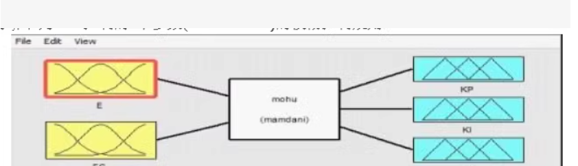
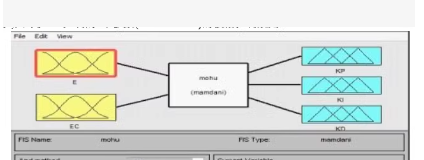
The image you’ve provided appears to be a diagram of a fuzzy logic system, specifically a Mamdani-type fuzzy inference system. This type of system is commonly used in control systems and decision-making processes where the inputs and outputs are described by linguistic variables rather than precise numerical values.
In this diagram:
- The inputs are labeled as ( E ) and ( EC ).
- The output is split into three components: ( KP ), ( KI ), and ( KD ), which likely correspond to the proportional, integral, and derivative terms in a PID (Proportional-Integral-Derivative) controller.
- The membership functions for the inputs and outputs are shown with different shapes, indicating the fuzzy sets that define the linguistic variables.
To implement this fuzzy logic system in code, you would typically use a programming language that supports fuzzy logic libraries or frameworks. Here is a basic example using Python with the scikit-fuzzy library:
import numpy as np
import skfuzzy as fuzz
from skfuzzy import control as ctrl

# Define new antecedents (inputs)
E = ctrl.Antecedent(np.arange(-10, 10, 1), 'error')
EC = ctrl.Antecedent(np.arange(-10, 10, 1), 'error_change')

# Define new consequents (outputs)
KP = ctrl.Consequent(np.arange(0, 5, 1), 'proportional_gain')
KI = ctrl.Consequent(np.arange(0, 5, 1), 'integral_gain')
KD = ctrl.Consequent(np.arange(0, 5, 1), 'derivative_gain')

# Auto-membership function population
E['negative'] = fuzz.trimf(E.universe, [-10, -5, 0])
E['zero'] = fuzz.trimf(E.universe, [-5, 0, 5])
E['positive'] = fuzz.trimf(E.universe, [0, 5, 10])

EC['negative'] = fuzz.trimf(EC.universe, [-10, -5, 0])
EC['zero'] = fuzz.trimf(EC.universe, [-5, 0, 5])
EC['positive'] = fuzz.trimf(EC.universe, [0, 5, 10])

KP['low'] = fuzz.trimf(KP.universe, [0, 0, 2.5])
KP['medium'] = fuzz.trimf(KP.universe, [0, 2.5, 5])
KP['high'] = fuzz.trimf(KP.universe, [2.5, 5, 5])

KI['low'] = fuzz.trimf(KI.universe, [0, 0, 2.5])
KI['medium'] = fuzz.trimf(KI.universe, [0, 2.5, 5])
KI['high'] = fuzz.trimf(KI.universe, [2.5, 5, 5])

KD['low'] = fuzz.trimf(KD.universe, [0, 0, 2.5])
KD['medium'] = fuzz.trimf(KD.universe, [0, 2.5, 5])
KD['high'] = fuzz.trimf(KD.universe, [2.5, 5, 5])

# Define the rules
rule1 = ctrl.Rule(E['negative'] & EC['negative'], KP['low'])
rule2 = ctrl.Rule(E['negative'] & EC['zero'], KP['medium'])
rule3 = ctrl.Rule(E['negative'] & EC['positive'], KP['high'])

rule4 = ctrl.Rule(E['zero'] & EC['negative'], KP['low'])
rule5 = ctrl.Rule(E['zero'] & EC['zero'], KP['medium'])
rule6 = ctrl.Rule(E['zero'] & EC['positive'], KP['high'])

rule7 = ctrl.Rule(E['positive'] & EC['negative'], KP['low'])
rule8 = ctrl.Rule(E['positive'] & EC['zero'], KP['medium'])
rule9 = ctrl.Rule(E['positive'] & EC['positive'], KP['high'])

# Create the control system
system = ctrl.ControlSystem([rule1, rule2, rule3, rule4, rule5, rule6, rule7, rule8, rule9])

# Simulate the system
simulation = ctrl.ControlSystemSimulation(system)

# Input values for error and error change
simulation.input['error'] = -5
simulation.input['error_change'] = 2

# Compute the output
simulation.compute()

# Print the output
print("Proportional Gain:", simulation.output['proportional_gain'])
This code defines the fuzzy sets and rules for the inputs and outputs based on the diagram. You can adjust the membership functions and rules to better match the specific requirements of your application.


 被折叠的 条评论
为什么被折叠?
被折叠的 条评论
为什么被折叠?
 到【灌水乐园】发言


