


大家好,我是在关东走西口的羊群!
在 3D 跑酷游戏开发中,我们经常面临一个看似无解的矛盾:项目预算有限,赛道必须程序化随机生成,但策划又要求道具必须精确配置在弯道上。
但传统的 3D 坐标计算方式,要求策划手动计算复杂曲率上的精确位置,这不仅工作量巨大,而且极易出错。
本篇文章将教你通过 3D 网格动态,构建高性能跑酷赛道!
这个跑道满足以下条件:
1. 由直线,左转弯,右转弯,上坡,下坡五种情况组成。
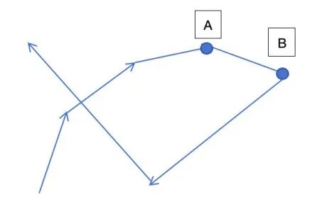
2. 即使有转弯,跑道也能保证其始终向前延伸的,不会出现下图中 B 点没有前进反而后退的情况。
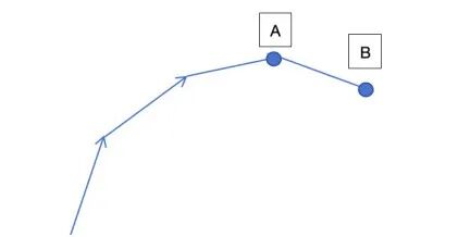
这可以避免当跑道长度太长时,可能出现的跑道重叠。
3. 策划可以很方便的将道具的位置配置到跑道上。
策划只需要将跑道当成一条直线来对待,可以大大减轻心智负担。
知道了跑道的宽度为 PathWidth,跑道的总长度为 PathLength 后,配置物体的坐标为:
X 坐标: [-PathWidth/2,PathWidth/2]
Z 坐标: [0,PathLength]
4. 可以指定跑道的最高点和最低点,让跑道在竖直方向上压缩到一个范围内。
Part.01
由点到线
我们首先在 3D 空间中动态生成一条跑线,而这个跑线则由许多的点组成。
为了能清晰的在编辑器中检测我们生成的点是否正确,我们先制作一个 PathPoint 预制件。创建一个空节点,然后将以下脚本挂在这个空节点上即可。
注意:该节点的绘制功能依赖 DebugDraw.ts 文件,请从 Github仓库上自取)
import { _decorator, Color, Component, Node, Vec3 } from"cc";
import { drawCube, drawLineFromTo } from"./DebugDraw";

const { ccclass, property, executeInEditMode } = _decorator;

@ccclass("PathPoint")
@executeInEditMode
exportclass PathPoint extends Component {
    @property({ type: Boolean })
    public drawDebug: boolean = true;

    public leftVertex: Vec3 = null;
    public rightVertex: Vec3 = null;

    start() {
    }

    update(deltaTime: number) {
        if (this.drawDebug) {
            // 画自己所在的位置
            let selfWorldPos = this.node.worldPosition;
            drawCube(selfWorldPos, 0.1, Color.RED);

            // 画路径线
            let next = this.node.getSiblingIndex() + 1;
            if (next < this.node.parent!.children.length) {
                let nextNode = this.node.parent!.children[next];
                let nextPos = nextNode.worldPosition;
                drawLineFromTo(selfWorldPos, nextPos, Color.YELLOW);
            }
        }
    }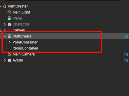
}接着,我们在场景上新建空节点PathCreate,设置位置为 (0, 0, 0)。
接着在它下边创建2个空的子节点PointContainer、ItemsContainer,如图所示。
接着我们创建脚本 PathCreateCtrl.ts 挂到PathCreate上。我们先定义好以下几个属性。
@ccclass("PathCreateCtr")
exportclass PathCreateCtr extends Component {
    // 路径点预制件
    @property(Prefab)
    pathPointPrefab: Prefab = null;

    // 路径点节点的容器
    @property(Node)
    pathPointContainer: Node = null;

    // 我们希望路径第一段永远是固定长度为firstSegmentLength的直线跑道
    @property(CCInteger)
    firstSegmentLength: number = 5;

    // 我们希望路径最后一段永远是固定长度为lastSegmentLength的直线跑道
    @property(CCInteger)
    lastSegmentLength: number = 5;

    @property(Node)
    public itemsContainer: Node = null!;

    // 路径网格
    private mesh: Mesh = new Mesh();

    // 一共会生成多少个路径点
    @property({ type: CCInteger })
    get pointCount(): number {
        returnthis._pointCount;
    }

    set pointCount(value: number) {
        this._pointCount = value;
        this.createPathPoint(value);
    }

    private _pointCount: number = 10;

    // 除去开头和结尾的长度,每个路径点之间的直线长度。
    // 此值越大,则路径越不平滑
    @property({ type: CCFloat })
    segmentLength: number = 1;

    // 路径在上坡和下坡的时候,每个路径线段之间的夹角是多少,此值越大,则坡度变化越大
    @property({ type: CCFloat })
    slopeAngle: number = 15;

    // 路径线段在上坡和下坡的时候允许的最大的角度是多少。
    @property({ type: CCFloat })
    maxSlopeAngle: number = 45;

    // 跑道的宽度
    @property({ type: CCFloat })
    pathWidth: number = 8;
}
接着我们来实现 createPathPoint 函数,我们先摆放好第一个路径段和最后一个路径段的位置。代码如下:
private createPathPoint(newValue: number) {
    if (newValue < 3) {
        this.pathPointContainer.removeAllChildren();
        console.warn("路径点数量不能少于3个");
        return;
    }

    // 先生成指定数量的路径点.
    let children = this.pathPointContainer.children;
    let currentLength = children.length;
    let needLength = newValue + 1; // 包括起点

    if (needLength > currentLength) {
        for (let i = currentLength; i < needLength; i++) {
            let newNode = instantiate(this.pathPointPrefab);
            newNode.parent = this.pathPointContainer;
        }
    } elseif (needLength < currentLength) {
        for (let i = currentLength - 1; i >= needLength; i--) {
            this.pathPointContainer.removeChild(children[i]);
        }
    }

    // 由 P0 到 P1的路径段l(0,1)为直线段,长度为 firstSegmentLength
    children = this.pathPointContainer.children;
    children[0].setPosition(0, 0, 0);
    children[1].setPosition(0, 0, -this.firstSegmentLength);

    // 生成中间的路径点,待定

    // 最后一段路径为直线,长度为lastSegmentLength
    // 先计算出前一个路径段的方向,接着延续这个方向即可
    let lastDir = Vec3.subtract(new Vec3(), children[needLength - 2].position, children[needLength - 3].position);
    lastDir = lastDir.normalize();
    let lastPos = Vec3.scaleAndAdd(new Vec3(), children[needLength - 2].position, lastDir, this.lastSegmentLength);
    children[needLength - 1].setPosition(lastPos);
}
接下来,我们讨论中间路径生成的情况。中间路径生成分为以下五种情况。
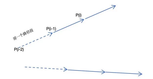
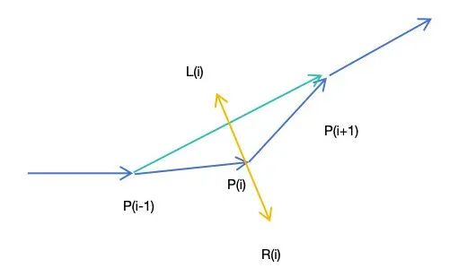
情况1:纯直线
如下图所示。这个时候,P(i) 的位置可以通过前一个路径段的方向乘以 segmentLength 得到。
对应的计算代码如下图所示:
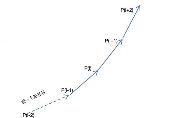
如果想要从i开始,连续 N 个路径点都是直线,则可以用如下代码:
let createDirecPath = (fromIndex: number) => {
    let dir = Vec3.subtract(new Vec3(), children[fromIndex - 1].position, children[fromIndex - 2].position);
    dir = dir.normalize();
    let newPos = Vec3.scaleAndAdd(new Vec3(), children[fromIndex - 1].position, dir, this.segmentLength);
    children[fromIndex].setPosition(newPos);
}
let createDirecPathArray = (fromIndex: number, count: number) => {
for (let j = 0; j < count; j++) {
let curIndex = fromIndex + j;
createDirecPath(curIndex);
}
}
情况2:水平面上的左转线段
如下图所示,从 P(i) 开始,后续的每个路径线段都在上一个路径线段的方向上水平向左旋转了slopeAngle。
在这里,必须保证 P(i-2)-P(i-1) 这条前置的路径段在Y轴上没有起落。
如果这前置路径段在Y轴有落差,则后边的线段就不会是水平的,而是有Y轴即竖直方向上有落差。
幸运的是,我们可以保证这一点。
这里的 Count 会有一个最大值限制,是为了防止这 N 个路径点累计的转弯角度超过90度,让跑道回头了,具体计算过程我们后边会提到。
对应的代码如下:
let createLeftTurnPath = (fromIndex: number, count: number) => {
    for (let j = 0; j < count; j++) {
        let curIndex = fromIndex + j;
        let dir = Vec3.subtract(new Vec3(), children[curIndex - 1].position, children[curIndex - 2].position);
        dir = dir.normalize();
        let up = new Vec3(0, 1, 0);
        let quat = new Quat();
        Quat.fromAxisAngle(quat, up, this.slopeAngle * Math.PI / 180);
        let leftDir = Vec3.transformQuat(new Vec3(), dir, quat);
        let newPos = Vec3.scaleAndAdd(new Vec3(), children[curIndex - 1].position, leftDir, this.segmentLength);

        // 如果弯度过大,导致当前的点z轴坐标大于前一个点的z轴坐标(路径回头了),则重新生成该点为直线。
        // 路径点的z应该是越来越小的。因为-Z为前进方向
        if (newPos.z > children[curIndex - 1].position.z) {
            createDirecPath(curIndex);
        } else {
            children[curIndex].setPosition(newPos);
        }
    }
}
情况3:水平方向的右转线段
这种情况和情况2是相同的,只不过是右转而已。理论上,createRightTurnPath 和 createLeftTurnPath 应该合并为一个函数,但为了理解更清晰分开使用。
具体代码如下:
let createRightTurnPath = (fromIndex: number, count: number) => {
    for (let j = 0; j < count; j++) {
        let curIndex = fromIndex + j;
        let dir = Vec3.subtract(new Vec3(), children[curIndex - 1].position, children[curIndex - 2].position);
        dir = dir.normalize();
        let up = new Vec3(0, 1, 0);
        let quat = new Quat();
        Quat.fromAxisAngle(quat, up, -this.slopeAngle * Math.PI / 180);
        let rightDir = Vec3.transformQuat(new Vec3(), dir, quat);
        let newPos = Vec3.scaleAndAdd(new Vec3(), children[curIndex - 1].position, rightDir, this.segmentLength);

        // 如果弯度过大,导致当前的点z轴坐标大于前一个点的z轴坐标(路径回头了),则重新生成该点为直线
        if (newPos.z > children[curIndex - 1].position.z) {
            createDirecPath(curIndex);
        } else {
            children[curIndex].setPosition(newPos);
        }
    }
}
情况4:竖直方向上的上坡曲线
如下图所示,从 P(i)-P(i+6) 构成了一个完整的上坡曲线,并且保证在 P(i+5)-P(i+6) 这条线段最后是水平的。
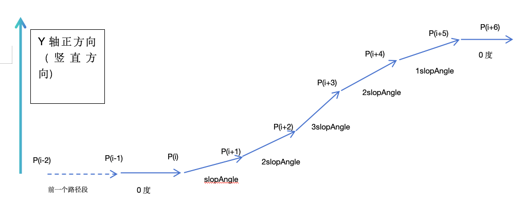
这样子就可以满足之前我提到的情况2的要求。从图中我们可以看出,组成上坡线段的段数 N 一定是为单数。具体计算代码如下:
// 当当前路径点设置为比前一个路径点在竖直方向上抬高angle度。
let createPitchPath = (fromIndex: number, angle: number) => {
    let dir = Vec3.subtract(new Vec3(), children[fromIndex - 1].position, children[fromIndex - 2].position);
    dir = dir.normalize();
    let right = Vec3.cross(new Vec3(), dir, Vec3.UP);
    right = right.normalize();
    let quat = new Quat();
    Quat.fromAxisAngle(quat, right, angle * Math.PI / 180);
    let pitchDir = Vec3.transformQuat(new Vec3(), dir, quat);
    let newPos = Vec3.scaleAndAdd(new Vec3(), children[fromIndex - 1].position, pitchDir, this.segmentLength);
    children[fromIndex].setPosition(newPos);
}

let createNoseUpPitchPath = (fromIndex: number, slopAngle: number, slopStep: number) => {
    createDirecPath(fromIndex);

    for (let l = 1; l < slopStep; l++) {
        if (l < slopStep / 2) {
            createPitchPath(fromIndex + l, slopAngle); //15
        } else {
            createPitchPath(fromIndex + l, -slopAngle); //15
        }
    }

    // 等价于
    // createPitchPath(fromIndex + 1, 15); //15
    // createPitchPath(fromIndex + 2, 15); //30
    // createPitchPath(fromIndex + 3, 15); //45
    // createPitchPath(fromIndex + 4, -15); //30
    // createPitchPath(fromIndex + 5, -15); // 15
    // createPitchPath(fromIndex + 6, -15); // 0
}
情况5:竖直方向上的下坡曲线
和情况4类似,这里不再赘述,具体代码如下:
let createNoseDownPitchPath = (fromIndex: number, slopAngle: number, slopStep: number) => {
    createDirecPath(fromIndex);

    for (let l = 1; l < slopStep; l++) {
        if (l < slopStep / 2) {
            createPitchPath(fromIndex + l, -slopAngle); //15
        } else {
            createPitchPath(fromIndex + l, +slopAngle); //15
        }
    }

    // 等价于
    // createPitchPath(fromIndex + 1, -15); //-15
    // createPitchPath(fromIndex + 2, -15); //-30
    // createPitchPath(fromIndex + 3, -15); //-45
    // createPitchPath(fromIndex + 4, 15); //-30
    // createPitchPath(fromIndex + 5, 15); // -15
    // createPitchPath(fromIndex + 6, 15); // 0
}
5种具体情况讨论完后,我们可以生成中间的路径点了。
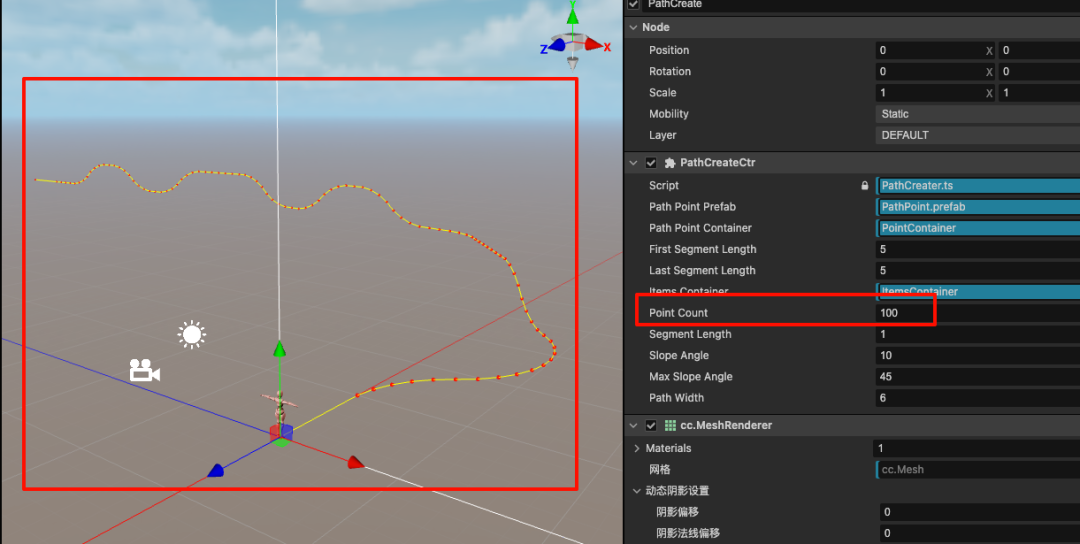
完成这些代码后,我们在编辑内修改一下属性面板上的 PointCount 的值,可以看到生成了路径点。
let i = 2;

// 爬坡或者下坡需要的路径点数量,假设我们的坡度变化为15度,最大坡度为45度,则需要7个路径点来完成一个完整的上坡和下坡
// 0 15 30 45 30 15 0
//如果坡度变化为10度,则需要10个路径点来完成一个完整的上坡和下坡
// 0 10 20 30 40 50 40 30 20 10 0
let slopeCount = Math.floor(this.maxSlopeAngle / this.slopeAngle) * 2 + 1;

// 单次转弯允许的最大段数,这里是为了防止一次转弯就累计到了90度,让路径点回头了
let maxTurnCount = Math.floor(90 / this.slopeAngle);

// 路径点的最低高度和最高高度,如果上坡之前发现当前高度已经达到最高了,就不会再上坡了
// 同理,下坡也是一样的道理
let minHight = 0 + 1.47;
let maxHight = 5 - 1.47;

while (i < needLength - 1) {
    // 0 直线
    // 1 左转
    // 2 右转
    // 3 上坡
    // 4 下坡
    let randomType = Math.floor(Math.random() * 5);

    if (randomType === 0) {
        let dirCectCount = Math.floor(Math.random() * maxTurnCount);

        // 如果剩余的路径点不足,则直接创建剩余的所有路径点为直线
        if (i + dirCectCount >= needLength - 1) {
            dirCectCount = needLength - 1 - i;
        }

        createDirecPathArray(i, dirCectCount);
        i += dirCectCount;
    } elseif (randomType === 1) {
        // 左转,随机N个路径点进行连续左转,只要N不超过maxTurnCount就行
        let turnCount = Math.floor(Math.random() * maxTurnCount);

        if (i + turnCount >= needLength - 1) {
            turnCount = needLength - 1 - i;
        }

        createLeftTurnPath(i, turnCount);
        i += turnCount;
    } elseif (randomType === 2) {
        // 右转,随机N个路径点进行连续右转,只要N不超过maxTurnCount就行
        let turnCount = Math.floor(Math.random() * maxTurnCount);

        if (i + turnCount >= needLength - 1) {
            turnCount = needLength - 1 - i;
        }

        createRightTurnPath(i, turnCount);
        i += turnCount;
    } elseif (randomType === 3) {
        // 如果当前高度已经达到最高了,就不会再上坡了,直接创建直线路径
        // 如果剩余的路径点数量不足以完成一个完整的上坡和下坡,则创建直线路径
        if (children[i - 1].position.y < maxHight && i + slopeCount < needLength - 1) {
            createNoseUpPitchPath(i, this.slopeAngle, slopeCount);
            i += slopeCount;
        } else {
            createDirecPath(i);
        }
    } else {
        // 如果当前高度已经达到最低了,就不会再下坡了,直接创建直线路径
        // 如果剩余的路径点数量不足以完成一个完整的上坡和下坡,则创建直线路径
        if (children[i - 1].position.y > minHight && i + slopeCount < needLength - 1) {
            createNoseDownPitchPath(i, this.slopeAngle, slopeCount);
            i += slopeCount;
        } else {
            createDirecPath(i);
        }
    }
}
Part.02
由线到面
在生成了路径后,我们就可以将这些点扩展成面了。
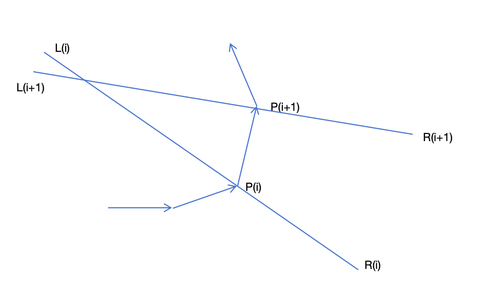
思路是先算出 P(i) 的切线方向,然后以这个朝向为正方向,做正方向的垂直线。左右各平移 PathWidth/2 个单位。如下图所示,其中:
P(0) 的切线方向就是 P(0)-P(1) 线段
P(N-1)的切线就是 P(N-2)-P(N-1) 线段
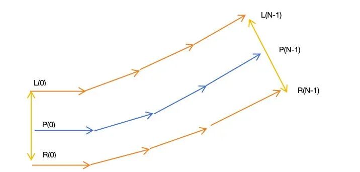
对于中间路径点 P(i),我们则将 P(i-i)-P(i+1) 作为这个点的切线。
根据该思路,我们来改造一下代码。
修改 PathPoint.ts中的 update 函数,用来帮忙画出 L(i) 和 R(i) 点,代码如下:
update(deltaTime: number) {
    if (this.drawDebug) {
        // 画自己所在的位置
        let selfWorldPos = this.node.worldPosition;
        drawCube(selfWorldPos, 0.1, Color.RED);

        // 画左右顶点
        if (this.leftVertex) {
            const worldPoint = new Vec3();
            Vec3.transformMat4(worldPoint, this.leftVertex, this.node.parent.worldMatrix);
            drawCube(worldPoint, 0.1, Color.BLUE);
            drawLineFromTo(selfWorldPos, worldPoint, Color.CYAN);
        }

        if (this.rightVertex) {
            const worldPoint = new Vec3();
            Vec3.transformMat4(worldPoint, this.rightVertex, this.node.parent.worldMatrix);
            drawCube(worldPoint, 0.1, Color.GREEN);
            drawLineFromTo(selfWorldPos, worldPoint, Color.CYAN);
        }

        // 画路径线
        let next = this.node.getSiblingIndex() + 1;
        if (next < this.node.parent!.children.length) {
            let nextNode = this.node.parent!.children[next];
            let nextPos = nextNode.worldPosition;
            drawLineFromTo(selfWorldPos, nextPos, Color.YELLOW);
        }
    }
}

// 在 PathCreater.ts 中将 set pointCount 函数修改如下
set pointCount(value: number) {
    this._pointCount = value;
    this.createPathPoint(value);
    this.createMeshData();
}
接着我们实现 createMeshData 函数private createMeshData() {
let children = this.pathPointContainer.children;
let currentLength = children.length;
if (currentLength < 2) {
console.warn("路径点数量不足,无法生成网格");
return;
}
let leftArray: Array<Vec3> = [];
let rightArray: Array<Vec3> = [];
// 计算每个路径点的左右顶点位置
for (let i = 0; i < currentLength; i++) {
let pathWidth = this.pathWidth;
let dir: Vec3;
if (i == 0) {
dir = Vec3.subtract(new Vec3(), children[i + 1].position, children[i].position);
} elseif (i == currentLength - 1) {
dir = Vec3.subtract(new Vec3(), children[i].position, children[i - 1].position);
} else {
dir = Vec3.subtract(new Vec3(), children[i + 1].position, children[i - 1].position);
}
dir = dir.normalize();
let right = Vec3.cross(new Vec3(), dir, Vec3.UP);
right = right.normalize();
let leftPoint = Vec3.scaleAndAdd(new Vec3(), children[i].position, right, -pathWidth / 2);
let rightPoint = Vec3.scaleAndAdd(new Vec3(), children[i].position, right, pathWidth / 2);
children[i].getComponent(PathPoint).leftVertex = leftPoint;
children[i].getComponent(PathPoint).rightVertex = rightPoint;
leftArray.push(leftPoint);
rightArray.push(rightPoint);
}
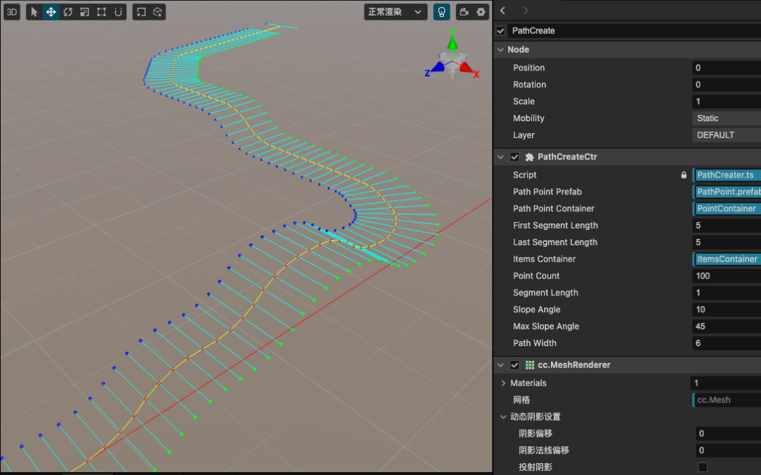
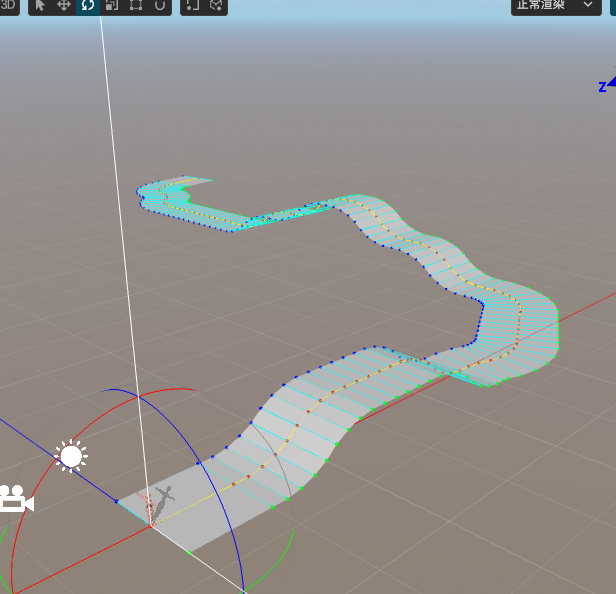
}做完这一步后,我们继续在编辑器中测试,可以看到结果如下图。
Part.03
由面到顶点数据
恭喜你,终于充满耐心看到这里了,接下来是激动人心的顶点数据填充环节。
对于每一个 P(i),我们先判断 P(i+1) 存在,如果存在就按照如下图的顺序来绘制三角形。
这里的顶点顺序需要满足右手螺旋定则。我们一次把 L(i+1)、L(i)、R(i) 和 L(i+1)、R(i)、R(i+1) 2个三角形加入顶点数据集合。
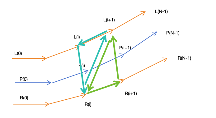
接着我们要算每个顶点的法线。如果没有法线,你会发现你生成的跑道不会有光照。
法线的计算也很简单,每个三角形顶点的法线等于与之相邻的两条边的叉乘。例如 R(i) 的法线等于 L(i+1)-R(i) 和 L(i)-R(i)的叉乘。
这里有个小技巧:由于两个三角形是完全共面的,所以只需要计算一个顶点的法线,就可以得到全部的六个法线。
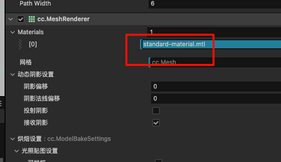
我们需要在PathCreate节点上添加MeshRenderer组件,为它选择一下默认的standard-material材质,如图所示。
然后继续在 createMeshData 里追加代码:
let vertices: number[] = newArray((currentLength - 1) * 6 * 3);
let normals: number[] = newArray((currentLength - 1) * 6 * 3);
let indices: number[] = newArray((currentLength - 1) * 2 * 3);
//顶点数据集
for (let i = 0; i < currentLength - 1; i++) {
let verticesStartIndex = i * 6 * 3;
// 左边三角形
vertices[verticesStartIndex + 0] = leftArray[i].x;
vertices[verticesStartIndex + 1] = leftArray[i].y;
vertices[verticesStartIndex + 2] = leftArray[i].z;
vertices[verticesStartIndex + 3] = rightArray[i].x;
vertices[verticesStartIndex + 4] = rightArray[i].y;
vertices[verticesStartIndex + 5] = rightArray[i].z;
vertices[verticesStartIndex + 6] = leftArray[i + 1].x;
vertices[verticesStartIndex + 7] = leftArray[i + 1].y;
vertices[verticesStartIndex + 8] = leftArray[i + 1].z;
// 右边三角形
vertices[verticesStartIndex + 9] = leftArray[i + 1].x;
vertices[verticesStartIndex + 10] = leftArray[i + 1].y;
vertices[verticesStartIndex + 11] = leftArray[i + 1].z;
vertices[verticesStartIndex + 12] = rightArray[i].x;
vertices[verticesStartIndex + 13] = rightArray[i].y;
vertices[verticesStartIndex + 14] = rightArray[i].z;
vertices[verticesStartIndex + 15] = rightArray[i + 1].x;
vertices[verticesStartIndex + 16] = rightArray[i + 1].y;
vertices[verticesStartIndex + 17] = rightArray[i + 1].z;
// 法线
let solveNormal = (target: Vec3, p1: Vec3, p2: Vec3) => {
let v1 = Vec3.subtract(new Vec3(), p1, target);
let v2 = Vec3.subtract(new Vec3(), p2, target);
let normal = Vec3.cross(new Vec3(), v1, v2);
normal = normal.normalize();
return normal;
}
let leftArrayN = solveNormal(leftArray[i], rightArray[i], leftArray[i + 1]);
let rightArrayN = leftArrayN; //solveNormal(rightArray[i], leftArray[i + 1], leftArray[i]);
let leftNextN = leftArrayN; //solveNormal(leftArray[i + 1], leftArray[i], rightArray[i]);
let leftNextN2 = leftArrayN; //solveNormal(leftArray[i + 1], rightArray[i], rightArray[i + 1]);
let rightN2 = leftNextN2; //solveNormal(rightArray[i], rightArray[i + 1], leftArray[i + 1]);
let rightNextN = leftNextN2; //solveNormal(rightArray[i + 1], leftArray[i + 1], rightArray[i]);
// 左边三角形
normals[verticesStartIndex + 0] = leftArrayN.x;
normals[verticesStartIndex + 1] = leftArrayN.y;
normals[verticesStartIndex + 2] = leftArrayN.z;
normals[verticesStartIndex + 3] = rightArrayN.x;
normals[verticesStartIndex + 4] = rightArrayN.y;
normals[verticesStartIndex + 5] = rightArrayN.z;
normals[verticesStartIndex + 6] = leftNextN.x;
normals[verticesStartIndex + 7] = leftNextN.y;
normals[verticesStartIndex + 8] = leftNextN.z;
// 右边三角形
normals[verticesStartIndex + 9] = leftNextN2.x;
normals[verticesStartIndex + 10] = leftNextN2.y;
normals[verticesStartIndex + 11] = leftNextN2.z;
normals[verticesStartIndex + 12] = rightN2.x;
normals[verticesStartIndex + 13] = rightN2.y;
normals[verticesStartIndex + 14] = rightN2.z;
normals[verticesStartIndex + 15] = rightNextN.x;
normals[verticesStartIndex + 16] = rightNextN.y;
normals[verticesStartIndex + 17] = rightNextN.z;
// 索引数据集
let indicesStartIndex = i * 2 * 3;
let vertexIndex = i * 6;
indices[indicesStartIndex + 0] = vertexIndex + 0;
indices[indicesStartIndex + 1] = vertexIndex + 1;
indices[indicesStartIndex + 2] = vertexIndex + 2;
indices[indicesStartIndex + 3] = vertexIndex + 3;
indices[indicesStartIndex + 4] = vertexIndex + 4;
indices[indicesStartIndex + 5] = vertexIndex + 5;
}
const mesh: Mesh = utils.MeshUtils.createMesh({
positions: vertices,
indices: indices,
normals: normals,
}, this.mesh);
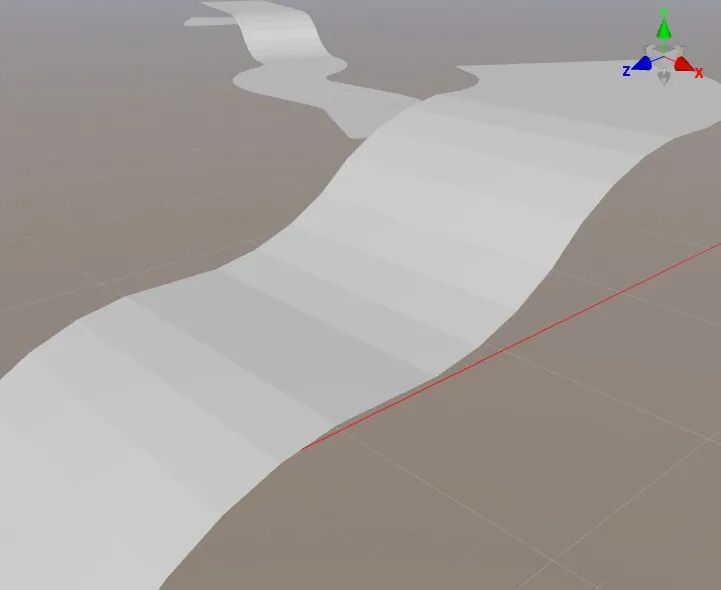
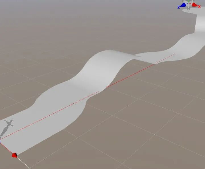
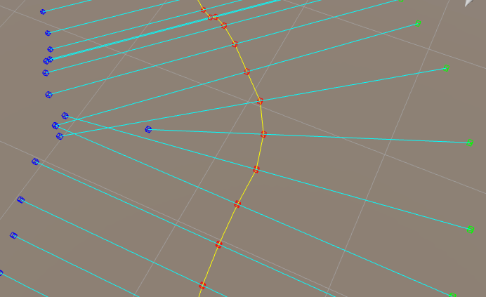
this.node.getComponent(MeshRenderer).mesh = this.mesh;继续在编辑器中测试,你会看到如下结果。至此,我们的路径生成已经结束了。
法线的优化
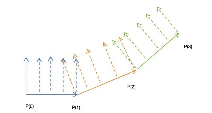
虽然基本网格已经生成了,但是只要仔细观察,会发现在上坡和下坡的地方,跑道的段落感非常的严重。
这是因为,在一个上坡的跑道上,蓝、橙、绿三条跑道的法线都在一条子跑道上,所以点的法线都是同一个方向。
因此,在进入下一个子跑道的时候,会有非常明显的明暗转折。
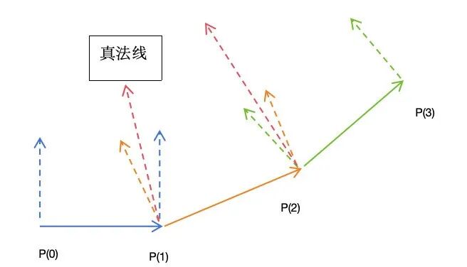
为了让法线的变化具有平滑性,我们应该把 P(1) 处的法线设置为2个法线的中间位置,如下图所示。为此,我们修改生成法线的相关代码如下:
// 法线
let solveNormal = (target: Vec3, p1: Vec3, p2: Vec3): Readonly<Vec3> => {
    let v1 = Vec3.subtract(new Vec3(), p1, target);
    let v2 = Vec3.subtract(new Vec3(), p2, target);
    let normal = Vec3.cross(new Vec3(), v1, v2);
    normal = normal.normalize();
    return normal;
}

let curMathNormal = solveNormal(leftArray[i], rightArray[i], leftArray[i + 1]);
let curTureNormal = new Vec3(curMathNormal);

if (preMathNormal) {
    curTureNormal = Vec3.add(new Vec3(), curMathNormal, preMathNormal).normalize();
    preMathNormal = new Vec3(curMathNormal);
}

// 左边三角形
normals[verticesStartIndex + 0] = curTureNormal.x;
normals[verticesStartIndex + 1] = curTureNormal.y;
normals[verticesStartIndex + 2] = curTureNormal.z;
normals[verticesStartIndex + 3] = curTureNormal.x;
normals[verticesStartIndex + 4] = curTureNormal.y;
normals[verticesStartIndex + 5] = curTureNormal.z;

// 这个点的法线在下个I会为重置
normals[verticesStartIndex + 6] = curMathNormal.x;
normals[verticesStartIndex + 7] = curMathNormal.y;
normals[verticesStartIndex + 8] = curMathNormal.z;

// 右边三角形
// 这个点的法线在下个I会为重置
normals[verticesStartIndex + 9] = curMathNormal.x;
normals[verticesStartIndex + 10] = curMathNormal.y;
normals[verticesStartIndex + 11] = curMathNormal.z;
normals[verticesStartIndex + 12] = curMathNormal.x;
normals[verticesStartIndex + 13] = curMathNormal.y;
normals[verticesStartIndex + 14] = curMathNormal.z;

// 这个点的法线在下个I会为重置
normals[verticesStartIndex + 15] = curMathNormal.x;
normals[verticesStartIndex + 16] = curMathNormal.y;
normals[verticesStartIndex + 17] = curMathNormal.z;

if (i > 1) {
    // 重置上个子路径的末尾的点的法线
    let preVerticesStartIndex = (i - 1) * 6 * 3;
    normals[preVerticesStartIndex + 6] = curTureNormal.x;
    normals[preVerticesStartIndex + 7] = curTureNormal.y;
    normals[preVerticesStartIndex + 8] = curTureNormal.z;
    normals[preVerticesStartIndex + 9] = curTureNormal.x;
    normals[preVerticesStartIndex + 10] = curTureNormal.y;
    normals[preVerticesStartIndex + 11] = curTureNormal.z;
    normals[preVerticesStartIndex + 15] = curTureNormal.x;
    normals[preVerticesStartIndex + 16] = curTureNormal.y;
    normals[preVerticesStartIndex + 17] = curTureNormal.z;
}
最终的效果也比较让人满意,可以看到,上下坡不再具有很强的段落感。
可怕的黑影
当我以为一切都趋于完美的时候,可怕的事情发生了,左转弯的地方出现了一大块黑影子。
出现这种情况的原因,是因为这条跑道的左边顶点出现了类似扇柄一样的错位。
这会导致按照如下图顶点连接起来的三角形 L(i+1)-L(i)-R(i) ,按照右手螺旋定则后,其正面面向了下边,而非上边,这导致了黑影。

上图情况下,L(i+1)-L(i)-R(i)构成的三角形面朝上,是正确的。
上图情况下,L(i+1)-L(i)-R(i) 构成的三角形面朝下了,会产生黑影。
我通过计算相邻的2条 L(i)R(i) 线段的交点,并缩短其中一条线段的方式,来避免相邻的 L(i)R(i) 线段中间有交缠。
但是如果仍旧不能消除黑影,那么可能是因为相邻的面片相互覆盖。
目前较好的建议是修改 SlopeAngle 和 PathWidth 的值,这2个值只要满足一定的条件,是不会出现 L(i)R(i) 相交的情况。
Part.04
小人跑酷
接着介绍下小人沿着跑道跑酷的逻辑。小人开跑的时候,记录所在的的子跑道的起点和终点路径点,并且根据这个子路径的方向设置好自己的朝向即可。
当达到了本条子跑道的终点时候,再将子跑道更新为下一段跑道。如下图所示。
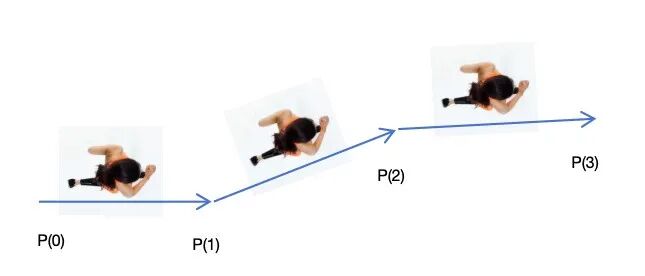
需要注意的是,当小人到达 P(1) 点时,不要直接将小人的朝向直接设置为 P(2)-P(1),这样子转弯会非常突兀。
正确的做法保存一个目标角度,在 update 里按照转角速度去修正自己的角度,这样会更加丝滑。
代码见项目中的 AvaterCtrl.ts部分。
Part.05
添加道具
有了路径点作为导航,那么添加道具就十分简单了。当我们填写好(vx,vz)的坐标后,假设首段和尾段的子路径不参与计算,那么我们需要计算道具放在哪个子跑道上:
let startPointIndex = Math.floor(vz / this.segmentLength) + 1;
let endPointIndex = startPointIndex + 1;

// 即可计算出子跑道的起点和终点序号。然后根据子跑道的方向算出来物体的朝向即可。

// 根据给出的虚拟位置,将物体放置到跑道上
public putItemByVirtualPosition(node: Node, vx: number, vz: number): boolean {
    let startPointIndex = Math.floor(vz / this.segmentLength) + 1;
    let endPointIndex = startPointIndex + 1;

    if (startPointIndex >= this.pathPointContainer.children.length - 1) {
        // 想要投放的物体已经超出了跑道的范围
        returnfalse;
    } else {
        let startPoint = this.pathPointContainer.children[startPointIndex];
        let endPoint = this.pathPointContainer.children[endPointIndex];
        let dir = Vec3.subtract(new Vec3(), endPoint.position, startPoint.position);
        dir = dir.normalize();

        let remainZ = vz - (startPointIndex - 1) * this.segmentLength;
        let pos = Vec3.scaleAndAdd(new Vec3(), startPoint.position, dir, remainZ);

        node.parent = this.itemsContainer;
        node.forward = dir;
        node.position = pos;

        let right = Vec3.cross(new Vec3(), dir, Vec3.UP).normalize();
        node.position = Vec3.scaleAndAdd(new Vec3(), node.position, right, vx);

        returntrue;
    }
}
Part.06
进阶思考
思考一:
目前生成的跑道是没有厚度的,你可以添加新的代码让跑道变成如下这个样子吗?
左右具有一个抬起来的边作为马路牙子,马路牙子上侧颜色可以自定义为蓝色或者别的颜色。
跑道具左右两侧有向下的侧边,具有厚度感。
思考二:
在可怕的黑影这个章节里,其实还有一种思路可以解决这个问题。
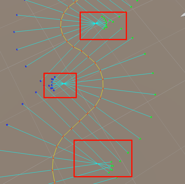
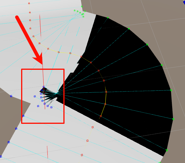
当 slopeAngle 和 PathWidth 足够大的时候,在左转或者右转时,一定会出现相邻左转或者右转路径点的所有 LR 线段都相交于一点。如下图所示。

幸运的是,我们是知道当前那些点是在左转和右转的。你可以重构代码,将每一个左转路径点的 L 点和右转路径点的 R 点缩回来一点,使得他们不相交吗?
如果有更优雅的解决方案,欢迎提交 PR 到 GitHub 仓库,期待你的加入!
点击【阅读原文】 或下方的 GitHub 链接,获取项目源码。
项目地址:
https://github.com/xiayangqun/CocosPathCreator
如果这篇文章对你有帮助,欢迎点赞、评论、转发!
我是晓衡,专注于游戏开发技术、开发者故事与个人感悟分享,如果公众号上的文章对你有所帮助或启发,欢迎点赞分享给更多朋友!
关注晓衡公众号,我会继续分享更多优质游戏资源与开发技巧。


 被折叠的 条评论
为什么被折叠?
被折叠的 条评论
为什么被折叠?
 到【灌水乐园】发言


