


〇、前言
LVGL 作为一款功能强大的开源嵌入式图形库,为资源有限的嵌入式设备带来了流畅美观的图形界面体验。然而,LVGL 的传统开发方式需要编写大量代码,对于初学者来说门槛较高,也增加了开发周期。而 SquareLine Studio 的出现,则完美解决了这些问题,为 LVGL 开发带来了以下优势:
1. 可视化开发,降低门槛:提供直观的可视化界面设计器,开发者无需编写代码即可通过拖拽控件、设置属性的方式快速构建用户界面,大大降低了 LVGL 的学习成本和开发难度,即使是没有编程经验的用户也能轻松上手。
2. 代码自动生成,提升效率:能够根据设计好的界面自动生成高质量的 LVGL 代码,开发者只需专注于业务逻辑的实现,无需手动编写繁琐的界面代码,极大地提高了开发效率,缩短了项目周期。
3. 实时预览,所见即所得: 支持实时预览功能,开发者可以随时查看界面设计效果,方便进行调试和修改,确保最终效果符合预期,避免反复修改代码的麻烦。
4. 跨平台支持,灵活便捷: 支持 Windows、macOS 和 Linux 系统,开发者可以在自己熟悉的操作系统上进行开发,同时,它支持多种嵌入式平台,包括 ESP32、ESP8266、STM32 等,方便将项目移植到不同的硬件平台。
5. 社区活跃,资源丰富: 有活跃的社区和丰富的学习资源,开发者可以轻松找到教程、示例代码和技术支持,快速解决开发过程中遇到的问题。
更多的SquareLine Studio信息和软件下载参考官方链接:https://squareline.io
这里不介绍如何安装SquareLine Studio(网上很多安装教程),直接从使用开始介绍。会介绍如何用SquareLine Studio创建一个Arduino工程,然后修改工程部分代码,让一些基本LVGL界面元素运行在esp8266上。
下面介绍使用到的硬件型号和软件版本如下:
| 软/硬件 | 版本/型号 |
| 操作系统 | win10 |
| SquareLine Studio | 1.5.0 |
| Arduino | 2.3.4 |
| nodeMcu | ESP8266-12F |
| 液晶屏 | ST7789 分辨率:240*240 |
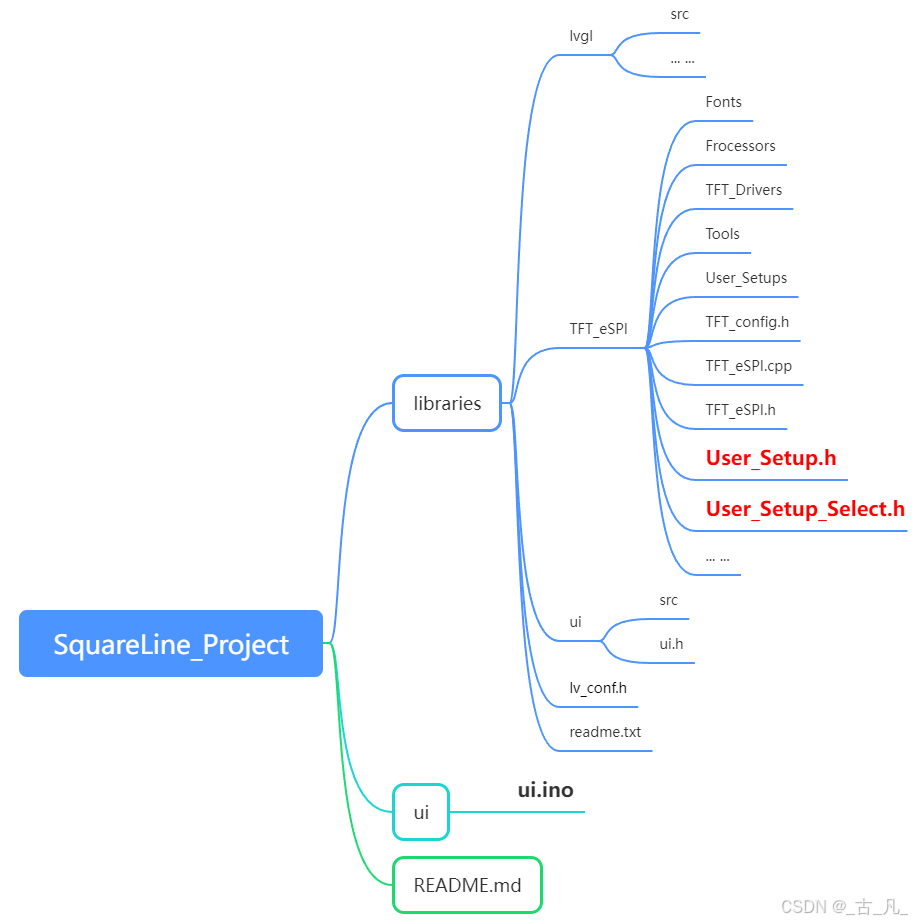
一、利用SquareLine Studio创建和导出Arduino工程
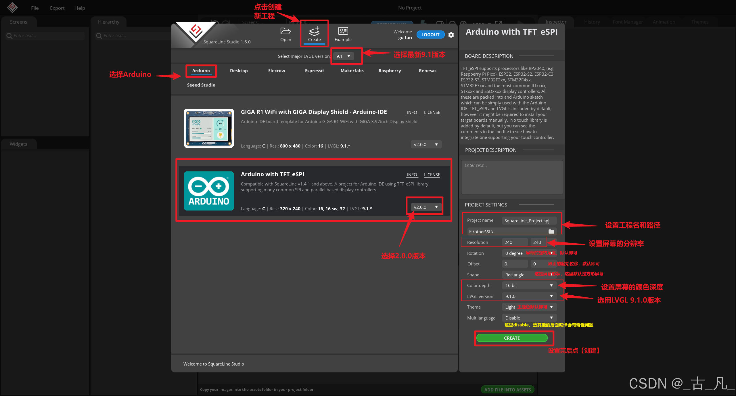
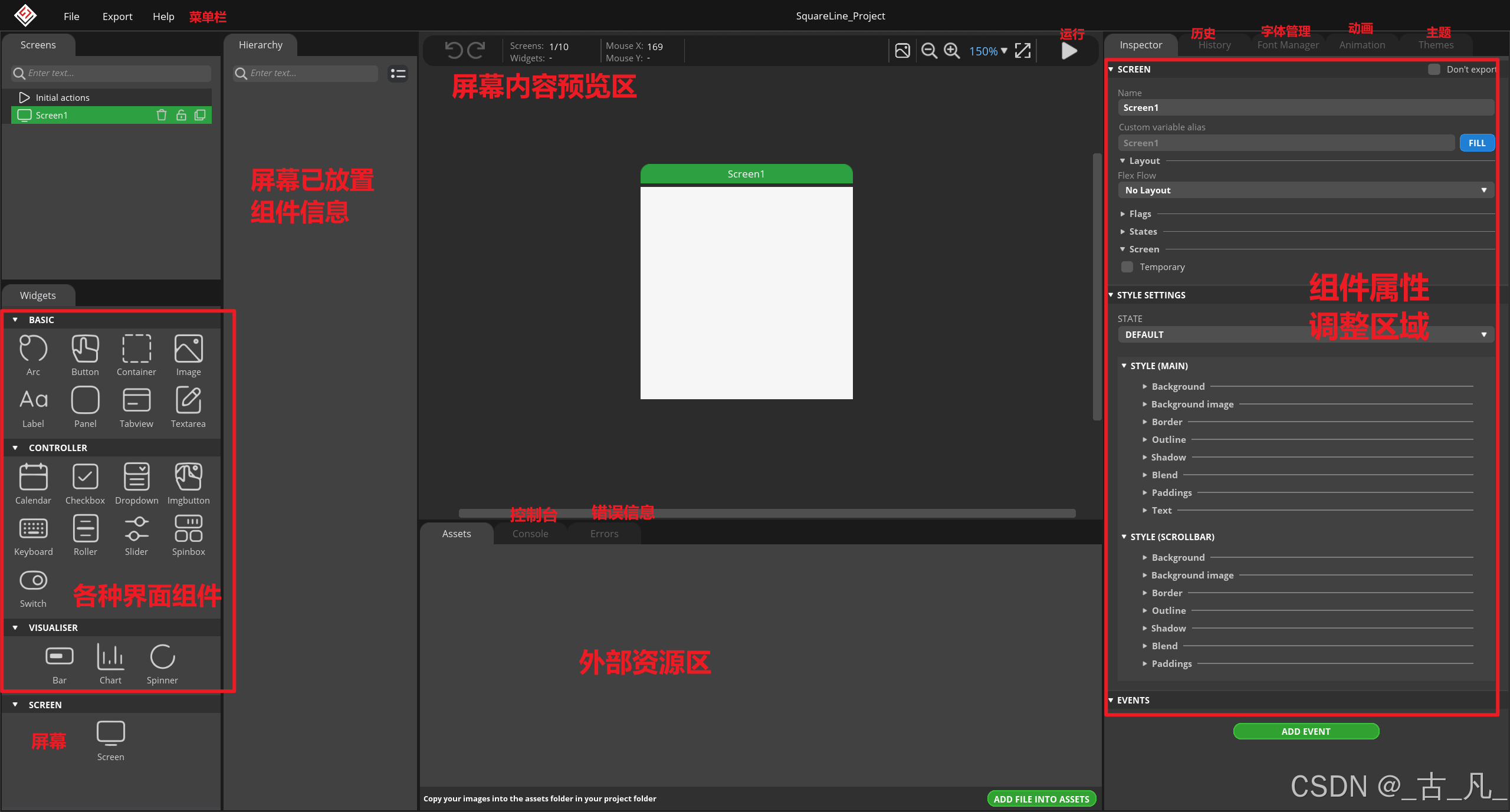
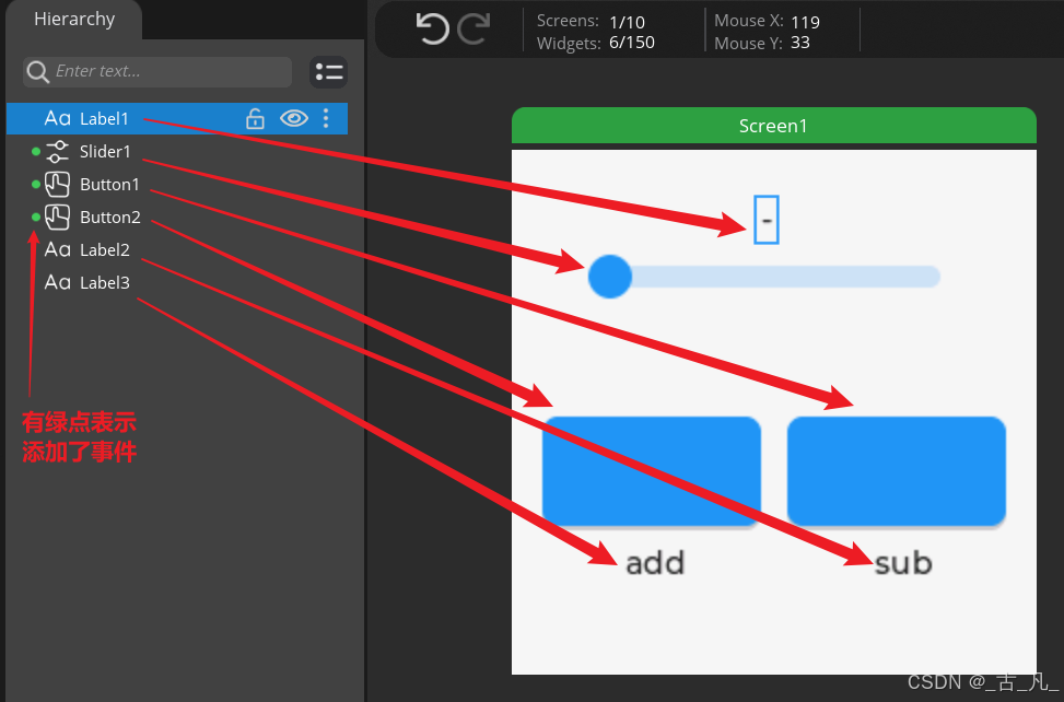
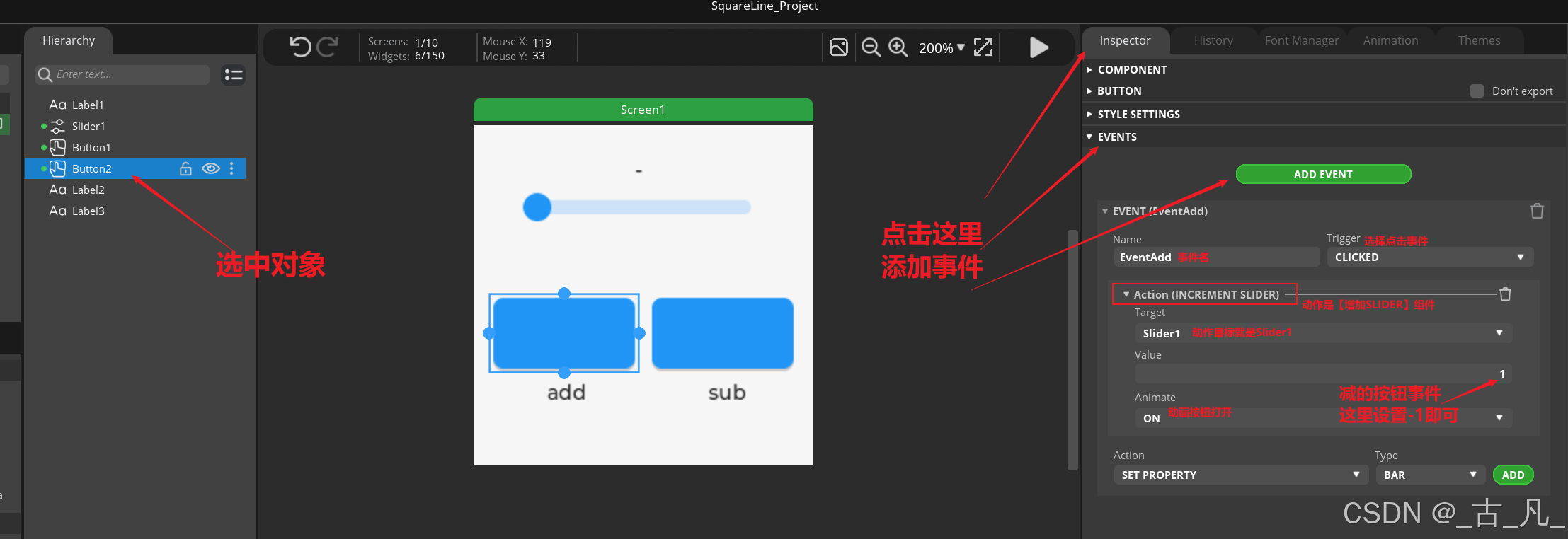
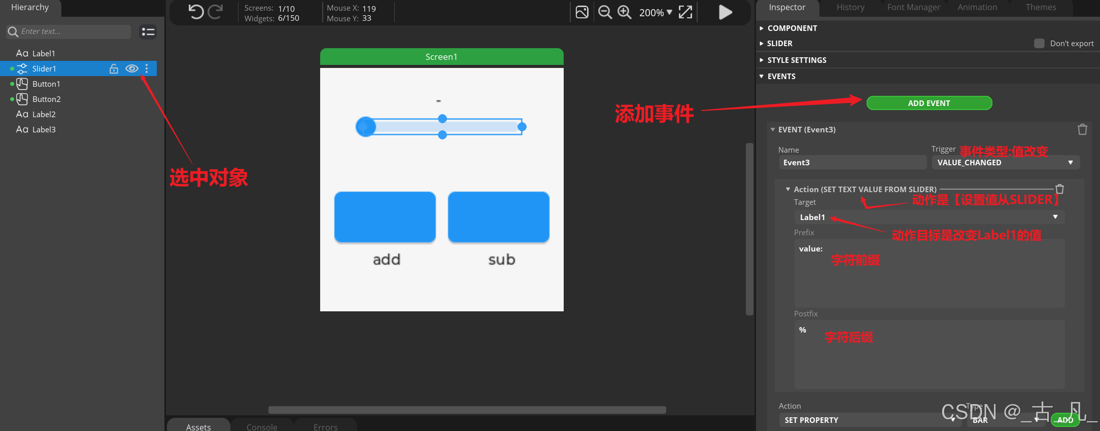
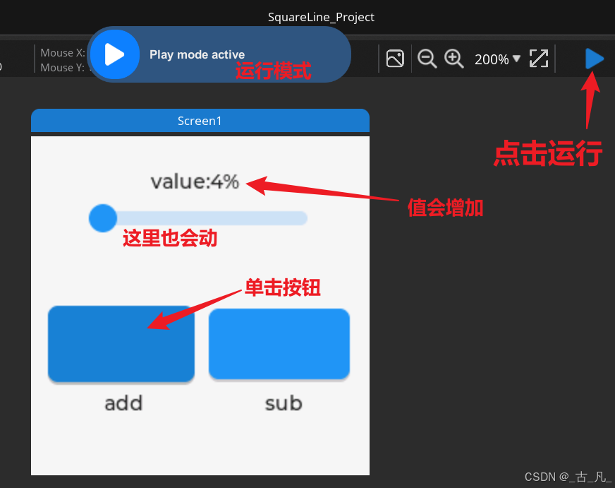
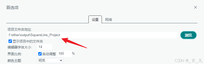
1.1 创建Arduino工程
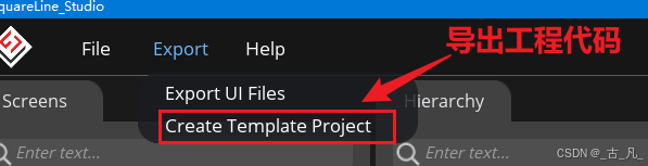
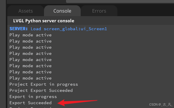
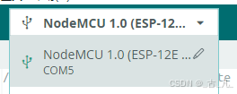
1.2 导出工程
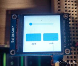
二、对Arduino工程部分做esp8266屏幕适配
2.1 修改步骤
- User_Setup_Select.h
//#include <User_Setups/Setup16_ILI9488_Parallel.h>  // Setup file for the ESP32 with parallel bus TFT
//#include <User_Setups/Setup17_ePaper.h>            // Setup file for ESP8266 and any Waveshare ePaper display
#include <User_Setups/Setup18_ST7789.h> // Setup file for ESP8266 configured for ST7789- User_Setup.h
// Only define one driver, the other ones must be commented out
//#define ILI9341_DRIVER // Generic driver for common displays
//#define ILI9341_2_DRIVER // Alternative ILI9341 driver, see https://github.com/Bodmer/TFT_eSPI/issues/1172
... ...
//#define ILI9488_DRIVER // WARNING: Do not connect ILI9488 display SDO to MISO if other devices share the SPI bus (TFT SDO does NOT tristate when CS is high)
#define ST7789_DRIVER // Full configuration option, define additional parameters below for this display// For ST7789, ST7735, ILI9163 and GC9A01 ONLY, define the pixel width and height in portrait orientation
// #define TFT_WIDTH 80
// #define TFT_WIDTH 128
// #define TFT_WIDTH 172 // ST7789 172 x 320
// #define TFT_WIDTH 170 // ST7789 170 x 320
#define TFT_WIDTH 240 // ST7789 240 x 240 and 240 x 320
// #define TFT_HEIGHT 160
// #define TFT_HEIGHT 128
#define TFT_HEIGHT 240 // ST7789 240 x 240
// #define TFT_HEIGHT 320 // ST7789 240 x 320
// #define TFT_HEIGHT 240 // GC9A01 240 x 240第三步:下载测试
|
nodeMcu引脚号
|
ESP8266-12F的IO引脚
|
屏幕引脚
|
|
D5
|
14
|
SCL
|
|
D7
|
13
|
SDA
|
|
D4
|
2
|
RES
|
|
D3
|
0
|
DC
|
|
VCC
|
VCC
|
BLK(背光)
|
2.2 可能的问题
2.2.1 屏幕颜色不对
// Identical looking TFT displays may have a different colour ordering in the 16-bit colour
#define TFT_BGR 0 // Colour order Blue-Green-Red
#define TFT_RGB 1 // Colour order Red-Green-Blue
User_Setup.h (76~77行左右)
// #define TFT_RGB_ORDER TFT_RGB // Colour order Red-Green-Blue
// #define TFT_RGB_ORDER TFT_BGR // Colour order Blue-Green-Red
lv_conf.h (26-29行左右)
/*Color depth: 8 (A8), 16 (RGB565), 24 (RGB888), 32 (XRGB8888)*/
#define LV_COLOR_DEPTH 16 //16
#define LV_COLOR_16_SWAP 0 //(LV_COLOR_16_SWAP is abandoned by LVGL9, but lv_draw_sw_rgb565_swap() is added to display flush function)2.2.2 如何修改引脚
// For NodeMCU - use pin numbers in the form PIN_Dx where Dx is the NodeMCU pin designation
#define TFT_DC PIN_D3 // Data Command control pin
#define TFT_RST PIN_D4 // Reset pin (could connect to NodeMCU RST, see next line)


 5503
5503

 被折叠的 条评论
为什么被折叠?
被折叠的 条评论
为什么被折叠?
 到【灌水乐园】发言


