


STM32 ADC和DMA简单总结
1.简介
使用野火开发板F429IGT6
ADC框图
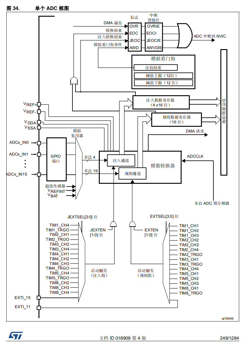
![[外链图片转存失败,源站可能有防盗链机制,建议将图片保存下来直接上传(img-hcRJQP6A-1656898707918)(https://raw.githubusercontent.com/Master-4869/pictures/main/image-20220702105905661.png)]](https://img-blog.csdnimg.cn/26097e67f47241a49214bce8140a7247.png)
ADC主要的选项配置有
- 时钟的分频配置,这个决定了ADC的时钟速度,
- 采样时钟数量,采样的时间长一点会更准,整个一个采样的周期是采样时间加上转换时间,如果使用12位的就需要加上12个时钟的转换时间,这样3个采样时间加上12个转换时间,整个采样周期就是15个周期
- 数据对齐的方式为左对齐还是右对齐,因为数据寄存器的宽度是16位的,采样的精度只能12位
- 扫描模式是同一个ADC开启多个通道,是否要轮流转换每个通道
- 连续采样是ADC是否要一直采样转换还是触发一次就停止转换
- EOC是转换结束标志
- 可以配置ADC的触发是软件触发还是硬件触发
- rank可以配置各个通道的转换先后顺序
- ADC可以分为规则转换通道和注入转换通道,一般用的就是规则转换通道
ADC还可以配置为多重采样的模式,一共有3个ADC,可以轮流来采样转换同一个通道,这样在第一个ADC转换的时候第二个可以紧接着采样,可以提升ADC的采样率。
![[外链图片转存失败,源站可能有防盗链机制,建议将图片保存下来直接上传(img-2GFsNAoN-1656898707918)(https://raw.githubusercontent.com/Master-4869/pictures/main/image-20220702111226199.png)]](https://img-blog.csdnimg.cn/d75366ef93014f9495549f099d2cfc92.png)
将3个ADC的相同通道选中,在ADC1的模式中选择三重采样。配置DMA以ADC1为主,其他ADC不需要配置,每个ADC都要打开循环检测模式。
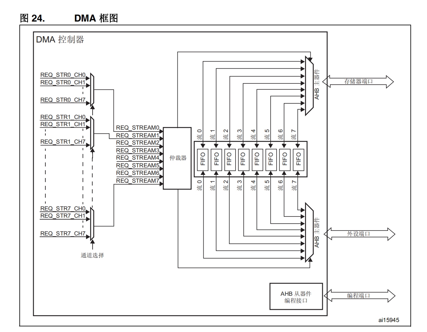

DMA的配置主要有
- 数据传输的方向,分为存储器到存储器,外设到存储器,存储器到外设
- 传输的模式是循环传输还是只传输一次
- 传输数据的宽度
- 传输时外设寄存器的地址和存储器的地址要不要递增,注意每次递增的地址的大小是和设置的数据宽度相同的
如果使用FIFO的话可以设置突发模式等
2.代码
使用cubemx6.6.0
MDK5.34
2.1多通道DMA
/* USER CODE BEGIN Header */
/**
  ******************************************************************************
  * @file    adc.c
  * @brief   This file provides code for the configuration
  *          of the ADC instances.
  ******************************************************************************
  * @attention
  *
  * Copyright (c) 2022 STMicroelectronics.
  * All rights reserved.
  *
  * This software is licensed under terms that can be found in the LICENSE file
  * in the root directory of this software component.
  * If no LICENSE file comes with this software, it is provided AS-IS.
  *
  ******************************************************************************
  */
/* USER CODE END Header */
/* Includes ------------------------------------------------------------------*/
#include "adc.h"

/* USER CODE BEGIN 0 */

/* USER CODE END 0 */

ADC_HandleTypeDef hadc1;
DMA_HandleTypeDef hdma_adc1;

/* ADC1 init function */
void MX_ADC1_Init(void)
{

  /* USER CODE BEGIN ADC1_Init 0 */

  /* USER CODE END ADC1_Init 0 */

  ADC_ChannelConfTypeDef sConfig = {0};

  /* USER CODE BEGIN ADC1_Init 1 */

  /* USER CODE END ADC1_Init 1 */

  /** Configure the global features of the ADC (Clock, Resolution, Data Alignment and number of conversion)
  */
  hadc1.Instance = ADC1;
  hadc1.Init.ClockPrescaler = ADC_CLOCK_SYNC_PCLK_DIV4;
  hadc1.Init.Resolution = ADC_RESOLUTION_12B;
  hadc1.Init.ScanConvMode = ENABLE;
  hadc1.Init.ContinuousConvMode = ENABLE;
  hadc1.Init.DiscontinuousConvMode = DISABLE;
  hadc1.Init.ExternalTrigConvEdge = ADC_EXTERNALTRIGCONVEDGE_NONE;
  hadc1.Init.ExternalTrigConv = ADC_SOFTWARE_START;
  hadc1.Init.DataAlign = ADC_DATAALIGN_RIGHT;
  hadc1.Init.NbrOfConversion = 3;
  hadc1.Init.DMAContinuousRequests = ENABLE;
  hadc1.Init.EOCSelection = ADC_EOC_SINGLE_CONV;
  if (HAL_ADC_Init(&hadc1) != HAL_OK)
  {
    Error_Handler();
  }

  /** Configure for the selected ADC regular channel its corresponding rank in the sequencer and its sample time.
  */
  sConfig.Channel = ADC_CHANNEL_13;
  sConfig.Rank = 1;
  sConfig.SamplingTime = ADC_SAMPLETIME_3CYCLES;
  if (HAL_ADC_ConfigChannel(&hadc1, &sConfig) != HAL_OK)
  {
    Error_Handler();
  }

  /** Configure for the selected ADC regular channel its corresponding rank in the sequencer and its sample time.
  */
  sConfig.Channel = ADC_CHANNEL_4;
  sConfig.Rank = 2;
  if (HAL_ADC_ConfigChannel(&hadc1, &sConfig) != HAL_OK)
  {
    Error_Handler();
  }

  /** Configure for the selected ADC regular channel its corresponding rank in the sequencer and its sample time.
  */
  sConfig.Channel = ADC_CHANNEL_6;
  sConfig.Rank = 3;
  if (HAL_ADC_ConfigChannel(&hadc1, &sConfig) != HAL_OK)
  {
    Error_Handler();
  }
  /* USER CODE BEGIN ADC1_Init 2 */
  /* USER CODE END ADC1_Init 2 */

}

void HAL_ADC_MspInit(ADC_HandleTypeDef* adcHandle)
{

  GPIO_InitTypeDef GPIO_InitStruct = {0};
  if(adcHandle->Instance==ADC1)
  {
  /* USER CODE BEGIN ADC1_MspInit 0 */

  /* USER CODE END ADC1_MspInit 0 */
    /* ADC1 clock enable */
    __HAL_RCC_ADC1_CLK_ENABLE();

    __HAL_RCC_GPIOC_CLK_ENABLE();
    __HAL_RCC_GPIOA_CLK_ENABLE();
    /**ADC1 GPIO Configuration
    PC3     ------> ADC1_IN13
    PA4     ------> ADC1_IN4
    PA6     ------> ADC1_IN6
    */
    GPIO_InitStruct.Pin = GPIO_PIN_3;
    GPIO_InitStruct.Mode = GPIO_MODE_ANALOG;
    GPIO_InitStruct.Pull = GPIO_NOPULL;
    HAL_GPIO_Init(GPIOC, &GPIO_InitStruct);

    GPIO_InitStruct.Pin = GPIO_PIN_4|GPIO_PIN_6;
    GPIO_InitStruct.Mode = GPIO_MODE_ANALOG;
    GPIO_InitStruct.Pull = GPIO_NOPULL;
    HAL_GPIO_Init(GPIOA, &GPIO_InitStruct);

    /* ADC1 DMA Init */
    /* ADC1 Init */
    hdma_adc1.Instance = DMA2_Stream0;
    hdma_adc1.Init.Channel = DMA_CHANNEL_0;
    hdma_adc1.Init.Direction = DMA_PERIPH_TO_MEMORY;
    hdma_adc1.Init.PeriphInc = DMA_PINC_DISABLE;
    hdma_adc1.Init.MemInc = DMA_MINC_ENABLE;
    hdma_adc1.Init.PeriphDataAlignment = DMA_PDATAALIGN_HALFWORD;
    hdma_adc1.Init.MemDataAlignment = DMA_MDATAALIGN_HALFWORD;
    hdma_adc1.Init.Mode = DMA_CIRCULAR;
    hdma_adc1.Init.Priority = DMA_PRIORITY_LOW;
    hdma_adc1.Init.FIFOMode = DMA_FIFOMODE_DISABLE;
    if (HAL_DMA_Init(&hdma_adc1) != HAL_OK)
    {
      Error_Handler();
    }

    __HAL_LINKDMA(adcHandle,DMA_Handle,hdma_adc1);

  /* USER CODE BEGIN ADC1_MspInit 1 */

  /* USER CODE END ADC1_MspInit 1 */
  }
}

void HAL_ADC_MspDeInit(ADC_HandleTypeDef* adcHandle)
{

  if(adcHandle->Instance==ADC1)
  {
  /* USER CODE BEGIN ADC1_MspDeInit 0 */

  /* USER CODE END ADC1_MspDeInit 0 */
    /* Peripheral clock disable */
    __HAL_RCC_ADC1_CLK_DISABLE();

    /**ADC1 GPIO Configuration
    PC3     ------> ADC1_IN13
    PA4     ------> ADC1_IN4
    PA6     ------> ADC1_IN6
    */
    HAL_GPIO_DeInit(GPIOC, GPIO_PIN_3);

    HAL_GPIO_DeInit(GPIOA, GPIO_PIN_4|GPIO_PIN_6);

    /* ADC1 DMA DeInit */
    HAL_DMA_DeInit(adcHandle->DMA_Handle);
  /* USER CODE BEGIN ADC1_MspDeInit 1 */

  /* USER CODE END ADC1_MspDeInit 1 */
  }
}

/* USER CODE BEGIN 1 */
//void HAL_ADC_ConvCpltCallback(ADC_HandleTypeDef* hadc)
//{
//	ADC_Value = HAL_ADC_GetValue(hadc);

//}
/* USER CODE END 1 */
/* USER CODE BEGIN Header */
/**
  ******************************************************************************
  * @file           : main.c
  * @brief          : Main program body
  ******************************************************************************
  * @attention
  *
  * Copyright (c) 2022 STMicroelectronics.
  * All rights reserved.
  *
  * This software is licensed under terms that can be found in the LICENSE file
  * in the root directory of this software component.
  * If no LICENSE file comes with this software, it is provided AS-IS.
  *
  ******************************************************************************
  */
/* USER CODE END Header */
/* Includes ------------------------------------------------------------------*/
#include "main.h"
#include "adc.h"
#include "dma.h"
#include "usart.h"
#include "gpio.h"

/* Private includes ----------------------------------------------------------*/
/* USER CODE BEGIN Includes */

/* USER CODE END Includes */

/* Private typedef -----------------------------------------------------------*/
/* USER CODE BEGIN PTD */

/* USER CODE END PTD */

/* Private define ------------------------------------------------------------*/
/* USER CODE BEGIN PD */
/* USER CODE END PD */

/* Private macro -------------------------------------------------------------*/
/* USER CODE BEGIN PM */

/* USER CODE END PM */

/* Private variables ---------------------------------------------------------*/

/* USER CODE BEGIN PV */
__IO uint16_t ADC_Value[300];
//extern UART_HandleTypeDef huart1;
/* USER CODE END PV */

/* Private function prototypes -----------------------------------------------*/
void SystemClock_Config(void);
/* USER CODE BEGIN PFP */

/* USER CODE END PFP */

/* Private user code ---------------------------------------------------------*/
/* USER CODE BEGIN 0 */

/* USER CODE END 0 */

/**
  * @brief  The application entry point.
  * @retval int
  */
int main(void)
{
  /* USER CODE BEGIN 1 */

  /* USER CODE END 1 */

  /* MCU Configuration--------------------------------------------------------*/

  /* Reset of all peripherals, Initializes the Flash interface and the Systick. */
  HAL_Init();

  /* USER CODE BEGIN Init */
	uint32_t chanel_value[3] = {0};
  /* USER CODE END Init */

  /* Configure the system clock */
  SystemClock_Config();

  /* USER CODE BEGIN SysInit */

  /* USER CODE END SysInit */

  /* Initialize all configured peripherals */
  MX_GPIO_Init();
  MX_DMA_Init();
  MX_ADC1_Init();
  MX_USART1_UART_Init();
  /* USER CODE BEGIN 2 */
	if (HAL_ADC_Start_DMA(&hadc1,(uint32_t *)&ADC_Value,300) == HAL_OK)
	{
		printf("dma开启成功\n\r");

	}
	else
		printf("dma开启失败\n\r");
  /* USER CODE END 2 */

  /* Infinite loop */
  /* USER CODE BEGIN WHILE */
  while (1)
  {
		chanel_value[0] = 0;
		chanel_value[1] = 0;
		chanel_value[2] = 0;
		for(int i = 0;i<300;)
		{
			chanel_value[0] += ADC_Value[i++];
			chanel_value[1] += ADC_Value[i++];
			chanel_value[2] += ADC_Value[i++];
		}
		chanel_value[0] = (float)chanel_value[0]/100;
		chanel_value[1] = (float)chanel_value[1]/100;
		chanel_value[2] = (float)chanel_value[2]/100;
		printf("\r\n------ ADC DMA ------\r\n\r\n");
    printf(" AD1 value = %1.3fV \r\n", chanel_value[0]*3.3f/4096);
    printf(" AD2 value = %1.3fV \r\n", chanel_value[1]*3.3f/4096);
		printf(" AD3 value = %1.3fV \r\n", chanel_value[2]*3.3f/4096);


		HAL_Delay(100);
    /* USER CODE END WHILE */

    /* USER CODE BEGIN 3 */
  }
  /* USER CODE END 3 */
}

/**
  * @brief System Clock Configuration
  * @retval None
  */
void SystemClock_Config(void)
{
  RCC_OscInitTypeDef RCC_OscInitStruct = {0};
  RCC_ClkInitTypeDef RCC_ClkInitStruct = {0};

  /** Configure the main internal regulator output voltage
  */
  __HAL_RCC_PWR_CLK_ENABLE();
  __HAL_PWR_VOLTAGESCALING_CONFIG(PWR_REGULATOR_VOLTAGE_SCALE1);

  /** Initializes the RCC Oscillators according to the specified parameters
  * in the RCC_OscInitTypeDef structure.
  */
  RCC_OscInitStruct.OscillatorType = RCC_OSCILLATORTYPE_HSE;
  RCC_OscInitStruct.HSEState = RCC_HSE_ON;
  RCC_OscInitStruct.PLL.PLLState = RCC_PLL_ON;
  RCC_OscInitStruct.PLL.PLLSource = RCC_PLLSOURCE_HSE;
  RCC_OscInitStruct.PLL.PLLM = 15;
  RCC_OscInitStruct.PLL.PLLN = 216;
  RCC_OscInitStruct.PLL.PLLP = RCC_PLLP_DIV2;
  RCC_OscInitStruct.PLL.PLLQ = 4;
  if (HAL_RCC_OscConfig(&RCC_OscInitStruct) != HAL_OK)
  {
    Error_Handler();
  }

  /** Activate the Over-Drive mode
  */
  if (HAL_PWREx_EnableOverDrive() != HAL_OK)
  {
    Error_Handler();
  }

  /** Initializes the CPU, AHB and APB buses clocks
  */
  RCC_ClkInitStruct.ClockType = RCC_CLOCKTYPE_HCLK|RCC_CLOCKTYPE_SYSCLK
                              |RCC_CLOCKTYPE_PCLK1|RCC_CLOCKTYPE_PCLK2;
  RCC_ClkInitStruct.SYSCLKSource = RCC_SYSCLKSOURCE_PLLCLK;
  RCC_ClkInitStruct.AHBCLKDivider = RCC_SYSCLK_DIV1;
  RCC_ClkInitStruct.APB1CLKDivider = RCC_HCLK_DIV4;
  RCC_ClkInitStruct.APB2CLKDivider = RCC_HCLK_DIV2;

  if (HAL_RCC_ClockConfig(&RCC_ClkInitStruct, FLASH_LATENCY_5) != HAL_OK)
  {
    Error_Handler();
  }
}

/* USER CODE BEGIN 4 */

/* USER CODE END 4 */

/**
  * @brief  This function is executed in case of error occurrence.
  * @retval None
  */
void Error_Handler(void)
{
  /* USER CODE BEGIN Error_Handler_Debug */
  /* User can add his own implementation to report the HAL error return state */
  __disable_irq();
  while (1)
  {
  }
  /* USER CODE END Error_Handler_Debug */
}

#ifdef  USE_FULL_ASSERT
/**
  * @brief  Reports the name of the source file and the source line number
  *         where the assert_param error has occurred.
  * @param  file: pointer to the source file name
  * @param  line: assert_param error line source number
  * @retval None
  */
void assert_failed(uint8_t *file, uint32_t line)
{
  /* USER CODE BEGIN 6 */
  /* User can add his own implementation to report the file name and line number,
     ex: printf("Wrong parameters value: file %s on line %d\r\n", file, line) */
  /* USER CODE END 6 */
}
#endif /* USE_FULL_ASSERT */
HAL_ADC_Start_DMA函数的作用就是启动ADC并且使用DMA传输数据。后面跟的数据长度要和自己设定的缓冲区长度一致,DMA会自动递增地址存放数据,递增设置的长度之后会自动复位地址重新开始从第一个地址写数据,覆盖掉之前的数据。
ADC规则通道只有一个数据寄存器, ADC_DR,在使能 DMA 模式的情况下(ADC_CR2 寄存器中的 DMA 位置 1),每完成规则通道组中的 一个通道转换后,都会生成一个 DMA 请求。这样便可将转换的数据从 ADC_DR 寄存器传输 到用软件选择的目标位置。
2.2三重ADC
/* USER CODE BEGIN Header */
/**
  ******************************************************************************
  * @file    adc.c
  * @brief   This file provides code for the configuration
  *          of the ADC instances.
  ******************************************************************************
  * @attention
  *
  * Copyright (c) 2022 STMicroelectronics.
  * All rights reserved.
  *
  * This software is licensed under terms that can be found in the LICENSE file
  * in the root directory of this software component.
  * If no LICENSE file comes with this software, it is provided AS-IS.
  *
  ******************************************************************************
  */
/* USER CODE END Header */
/* Includes ------------------------------------------------------------------*/
#include "adc.h"

/* USER CODE BEGIN 0 */

/* USER CODE END 0 */

ADC_HandleTypeDef hadc1;
ADC_HandleTypeDef hadc2;
ADC_HandleTypeDef hadc3;
DMA_HandleTypeDef hdma_adc1;

/* ADC1 init function */
void MX_ADC1_Init(void)
{

  /* USER CODE BEGIN ADC1_Init 0 */

  /* USER CODE END ADC1_Init 0 */

  ADC_MultiModeTypeDef multimode = {0};
  ADC_ChannelConfTypeDef sConfig = {0};

  /* USER CODE BEGIN ADC1_Init 1 */

  /* USER CODE END ADC1_Init 1 */

  /** Configure the global features of the ADC (Clock, Resolution, Data Alignment and number of conversion)
  */
  hadc1.Instance = ADC1;
  hadc1.Init.ClockPrescaler = ADC_CLOCK_SYNC_PCLK_DIV4;
  hadc1.Init.Resolution = ADC_RESOLUTION_12B;
  hadc1.Init.ScanConvMode = DISABLE;
  hadc1.Init.ContinuousConvMode = ENABLE;
  hadc1.Init.DiscontinuousConvMode = DISABLE;
  hadc1.Init.ExternalTrigConvEdge = ADC_EXTERNALTRIGCONVEDGE_NONE;
  hadc1.Init.ExternalTrigConv = ADC_SOFTWARE_START;
  hadc1.Init.DataAlign = ADC_DATAALIGN_RIGHT;
  hadc1.Init.NbrOfConversion = 1;
  hadc1.Init.DMAContinuousRequests = ENABLE;
  hadc1.Init.EOCSelection = ADC_EOC_SINGLE_CONV;
  if (HAL_ADC_Init(&hadc1) != HAL_OK)
  {
    Error_Handler();
  }

  /** Configure the ADC multi-mode
  */
  multimode.Mode = ADC_TRIPLEMODE_INTERL;
  multimode.DMAAccessMode = ADC_DMAACCESSMODE_2;
  multimode.TwoSamplingDelay = ADC_TWOSAMPLINGDELAY_5CYCLES;
  if (HAL_ADCEx_MultiModeConfigChannel(&hadc1, &multimode) != HAL_OK)
  {
    Error_Handler();
  }

  /** Configure for the selected ADC regular channel its corresponding rank in the sequencer and its sample time.
  */
  sConfig.Channel = ADC_CHANNEL_13;
  sConfig.Rank = 1;
  sConfig.SamplingTime = ADC_SAMPLETIME_3CYCLES;
  if (HAL_ADC_ConfigChannel(&hadc1, &sConfig) != HAL_OK)
  {
    Error_Handler();
  }
  /* USER CODE BEGIN ADC1_Init 2 */

  /* USER CODE END ADC1_Init 2 */

}
/* ADC2 init function */
void MX_ADC2_Init(void)
{

  /* USER CODE BEGIN ADC2_Init 0 */

  /* USER CODE END ADC2_Init 0 */

  ADC_ChannelConfTypeDef sConfig = {0};

  /* USER CODE BEGIN ADC2_Init 1 */

  /* USER CODE END ADC2_Init 1 */

  /** Configure the global features of the ADC (Clock, Resolution, Data Alignment and number of conversion)
  */
  hadc2.Instance = ADC2;
  hadc2.Init.ClockPrescaler = ADC_CLOCK_SYNC_PCLK_DIV4;
  hadc2.Init.Resolution = ADC_RESOLUTION_12B;
  hadc2.Init.ScanConvMode = DISABLE;
  hadc2.Init.ContinuousConvMode = ENABLE;
  hadc2.Init.DiscontinuousConvMode = DISABLE;
  hadc2.Init.DataAlign = ADC_DATAALIGN_RIGHT;
  hadc2.Init.NbrOfConversion = 1;
  hadc2.Init.DMAContinuousRequests = DISABLE;
  hadc2.Init.EOCSelection = ADC_EOC_SINGLE_CONV;
  if (HAL_ADC_Init(&hadc2) != HAL_OK)
  {
    Error_Handler();
  }

  /** Configure for the selected ADC regular channel its corresponding rank in the sequencer and its sample time.
  */
  sConfig.Channel = ADC_CHANNEL_13;
  sConfig.Rank = 1;
  sConfig.SamplingTime = ADC_SAMPLETIME_3CYCLES;
  if (HAL_ADC_ConfigChannel(&hadc2, &sConfig) != HAL_OK)
  {
    Error_Handler();
  }
  /* USER CODE BEGIN ADC2_Init 2 */

  /* USER CODE END ADC2_Init 2 */

}
/* ADC3 init function */
void MX_ADC3_Init(void)
{

  /* USER CODE BEGIN ADC3_Init 0 */

  /* USER CODE END ADC3_Init 0 */

  ADC_ChannelConfTypeDef sConfig = {0};

  /* USER CODE BEGIN ADC3_Init 1 */

  /* USER CODE END ADC3_Init 1 */

  /** Configure the global features of the ADC (Clock, Resolution, Data Alignment and number of conversion)
  */
  hadc3.Instance = ADC3;
  hadc3.Init.ClockPrescaler = ADC_CLOCK_SYNC_PCLK_DIV4;
  hadc3.Init.Resolution = ADC_RESOLUTION_12B;
  hadc3.Init.ScanConvMode = DISABLE;
  hadc3.Init.ContinuousConvMode = ENABLE;
  hadc3.Init.DiscontinuousConvMode = DISABLE;
  hadc3.Init.DataAlign = ADC_DATAALIGN_RIGHT;
  hadc3.Init.NbrOfConversion = 1;
  hadc3.Init.DMAContinuousRequests = DISABLE;
  hadc3.Init.EOCSelection = ADC_EOC_SINGLE_CONV;
  if (HAL_ADC_Init(&hadc3) != HAL_OK)
  {
    Error_Handler();
  }

  /** Configure for the selected ADC regular channel its corresponding rank in the sequencer and its sample time.
  */
  sConfig.Channel = ADC_CHANNEL_13;
  sConfig.Rank = 1;
  sConfig.SamplingTime = ADC_SAMPLETIME_3CYCLES;
  if (HAL_ADC_ConfigChannel(&hadc3, &sConfig) != HAL_OK)
  {
    Error_Handler();
  }
  /* USER CODE BEGIN ADC3_Init 2 */

  /* USER CODE END ADC3_Init 2 */

}

void HAL_ADC_MspInit(ADC_HandleTypeDef* adcHandle)
{

  GPIO_InitTypeDef GPIO_InitStruct = {0};
  if(adcHandle->Instance==ADC1)
  {
  /* USER CODE BEGIN ADC1_MspInit 0 */

  /* USER CODE END ADC1_MspInit 0 */
    /* ADC1 clock enable */
    __HAL_RCC_ADC1_CLK_ENABLE();

    __HAL_RCC_GPIOC_CLK_ENABLE();
    /**ADC1 GPIO Configuration
    PC3     ------> ADC1_IN13
    */
    GPIO_InitStruct.Pin = GPIO_PIN_3;
    GPIO_InitStruct.Mode = GPIO_MODE_ANALOG;
    GPIO_InitStruct.Pull = GPIO_NOPULL;
    HAL_GPIO_Init(GPIOC, &GPIO_InitStruct);

    /* ADC1 DMA Init */
    /* ADC1 Init */
    hdma_adc1.Instance = DMA2_Stream0;
    hdma_adc1.Init.Channel = DMA_CHANNEL_0;
    hdma_adc1.Init.Direction = DMA_PERIPH_TO_MEMORY;
    hdma_adc1.Init.PeriphInc = DMA_PINC_DISABLE;
    hdma_adc1.Init.MemInc = DMA_MINC_ENABLE;
    hdma_adc1.Init.PeriphDataAlignment = DMA_PDATAALIGN_WORD;
    hdma_adc1.Init.MemDataAlignment = DMA_MDATAALIGN_WORD;
    hdma_adc1.Init.Mode = DMA_CIRCULAR;
    hdma_adc1.Init.Priority = DMA_PRIORITY_LOW;
    hdma_adc1.Init.FIFOMode = DMA_FIFOMODE_DISABLE;
    if (HAL_DMA_Init(&hdma_adc1) != HAL_OK)
    {
      Error_Handler();
    }

    __HAL_LINKDMA(adcHandle,DMA_Handle,hdma_adc1);

  /* USER CODE BEGIN ADC1_MspInit 1 */

  /* USER CODE END ADC1_MspInit 1 */
  }
  else if(adcHandle->Instance==ADC2)
  {
  /* USER CODE BEGIN ADC2_MspInit 0 */

  /* USER CODE END ADC2_MspInit 0 */
    /* ADC2 clock enable */
    __HAL_RCC_ADC2_CLK_ENABLE();

    __HAL_RCC_GPIOC_CLK_ENABLE();
    /**ADC2 GPIO Configuration
    PC3     ------> ADC2_IN13
    */
    GPIO_InitStruct.Pin = GPIO_PIN_3;
    GPIO_InitStruct.Mode = GPIO_MODE_ANALOG;
    GPIO_InitStruct.Pull = GPIO_NOPULL;
    HAL_GPIO_Init(GPIOC, &GPIO_InitStruct);

  /* USER CODE BEGIN ADC2_MspInit 1 */

  /* USER CODE END ADC2_MspInit 1 */
  }
  else if(adcHandle->Instance==ADC3)
  {
  /* USER CODE BEGIN ADC3_MspInit 0 */

  /* USER CODE END ADC3_MspInit 0 */
    /* ADC3 clock enable */
    __HAL_RCC_ADC3_CLK_ENABLE();

    __HAL_RCC_GPIOC_CLK_ENABLE();
    /**ADC3 GPIO Configuration
    PC3     ------> ADC3_IN13
    */
    GPIO_InitStruct.Pin = GPIO_PIN_3;
    GPIO_InitStruct.Mode = GPIO_MODE_ANALOG;
    GPIO_InitStruct.Pull = GPIO_NOPULL;
    HAL_GPIO_Init(GPIOC, &GPIO_InitStruct);

  /* USER CODE BEGIN ADC3_MspInit 1 */

  /* USER CODE END ADC3_MspInit 1 */
  }
}

void HAL_ADC_MspDeInit(ADC_HandleTypeDef* adcHandle)
{

  if(adcHandle->Instance==ADC1)
  {
  /* USER CODE BEGIN ADC1_MspDeInit 0 */

  /* USER CODE END ADC1_MspDeInit 0 */
    /* Peripheral clock disable */
    __HAL_RCC_ADC1_CLK_DISABLE();

    /**ADC1 GPIO Configuration
    PC3     ------> ADC1_IN13
    */
    HAL_GPIO_DeInit(GPIOC, GPIO_PIN_3);

    /* ADC1 DMA DeInit */
    HAL_DMA_DeInit(adcHandle->DMA_Handle);
  /* USER CODE BEGIN ADC1_MspDeInit 1 */

  /* USER CODE END ADC1_MspDeInit 1 */
  }
  else if(adcHandle->Instance==ADC2)
  {
  /* USER CODE BEGIN ADC2_MspDeInit 0 */

  /* USER CODE END ADC2_MspDeInit 0 */
    /* Peripheral clock disable */
    __HAL_RCC_ADC2_CLK_DISABLE();

    /**ADC2 GPIO Configuration
    PC3     ------> ADC2_IN13
    */
    HAL_GPIO_DeInit(GPIOC, GPIO_PIN_3);

  /* USER CODE BEGIN ADC2_MspDeInit 1 */

  /* USER CODE END ADC2_MspDeInit 1 */
  }
  else if(adcHandle->Instance==ADC3)
  {
  /* USER CODE BEGIN ADC3_MspDeInit 0 */

  /* USER CODE END ADC3_MspDeInit 0 */
    /* Peripheral clock disable */
    __HAL_RCC_ADC3_CLK_DISABLE();

    /**ADC3 GPIO Configuration
    PC3     ------> ADC3_IN13
    */
    HAL_GPIO_DeInit(GPIOC, GPIO_PIN_3);

  /* USER CODE BEGIN ADC3_MspDeInit 1 */

  /* USER CODE END ADC3_MspDeInit 1 */
  }
}

/* USER CODE BEGIN 1 */

/* USER CODE END 1 */
/* USER CODE BEGIN Header */
/**
  ******************************************************************************
  * @file           : main.c
  * @brief          : Main program body
  ******************************************************************************
  * @attention
  *
  * Copyright (c) 2022 STMicroelectronics.
  * All rights reserved.
  *
  * This software is licensed under terms that can be found in the LICENSE file
  * in the root directory of this software component.
  * If no LICENSE file comes with this software, it is provided AS-IS.
  *
  ******************************************************************************
  */
/* USER CODE END Header */
/* Includes ------------------------------------------------------------------*/
#include "main.h"
#include "adc.h"
#include "dma.h"
#include "usart.h"
#include "gpio.h"

/* Private includes ----------------------------------------------------------*/
/* USER CODE BEGIN Includes */

/* USER CODE END Includes */

/* Private typedef -----------------------------------------------------------*/
/* USER CODE BEGIN PTD */

/* USER CODE END PTD */

/* Private define ------------------------------------------------------------*/
/* USER CODE BEGIN PD */
uint32_t adc_buffer[300] = {0};
/* USER CODE END PD */

/* Private macro -------------------------------------------------------------*/
/* USER CODE BEGIN PM */

/* USER CODE END PM */

/* Private variables ---------------------------------------------------------*/

/* USER CODE BEGIN PV */

/* USER CODE END PV */

/* Private function prototypes -----------------------------------------------*/
void SystemClock_Config(void);
/* USER CODE BEGIN PFP */

/* USER CODE END PFP */

/* Private user code ---------------------------------------------------------*/
/* USER CODE BEGIN 0 */

/* USER CODE END 0 */

/**
  * @brief  The application entry point.
  * @retval int
  */
int main(void)
{
  /* USER CODE BEGIN 1 */

  /* USER CODE END 1 */

  /* MCU Configuration--------------------------------------------------------*/

  /* Reset of all peripherals, Initializes the Flash interface and the Systick. */
  HAL_Init();

  /* USER CODE BEGIN Init */

  /* USER CODE END Init */

  /* Configure the system clock */
  SystemClock_Config();

  /* USER CODE BEGIN SysInit */

  /* USER CODE END SysInit */

  /* Initialize all configured peripherals */
  MX_GPIO_Init();
  MX_DMA_Init();
  MX_ADC1_Init();
  MX_ADC2_Init();
  MX_ADC3_Init();
  MX_USART1_UART_Init();
  /* USER CODE BEGIN 2 */
	printf("\r\n------ ADC DMA ------\r\n\r\n");
	HAL_ADC_Start(&hadc3);
	HAL_ADC_Start(&hadc2);
	HAL_ADCEx_MultiModeStart_DMA(&hadc1,adc_buffer,300);

  /* USER CODE END 2 */

  /* Infinite loop */
  /* USER CODE BEGIN WHILE */
  while (1)
  {
    /* USER CODE END WHILE */
		printf("\r\n------ ADC DMA ------\r\n\r\n");
		printf(" AD1 value = %1.3fV \r\n", (uint16_t)adc_buffer[0]*3.3f/4096);
		printf(" AD1 value = %1.3fV \r\n", (adc_buffer[0]>>16)*3.3f/4096);
		printf(" AD1 value = %1.3fV \r\n", (uint16_t)adc_buffer[1]*3.3f/4096);
		printf(" AD1 value = %1.3fV \r\n", (adc_buffer[1]>>16)*3.3f/4096);
		HAL_Delay(100);

    /* USER CODE BEGIN 3 */
  }
  /* USER CODE END 3 */
}

/**
  * @brief System Clock Configuration
  * @retval None
  */
void SystemClock_Config(void)
{
  RCC_OscInitTypeDef RCC_OscInitStruct = {0};
  RCC_ClkInitTypeDef RCC_ClkInitStruct = {0};

  /** Configure the main internal regulator output voltage
  */
  __HAL_RCC_PWR_CLK_ENABLE();
  __HAL_PWR_VOLTAGESCALING_CONFIG(PWR_REGULATOR_VOLTAGE_SCALE1);

  /** Initializes the RCC Oscillators according to the specified parameters
  * in the RCC_OscInitTypeDef structure.
  */
  RCC_OscInitStruct.OscillatorType = RCC_OSCILLATORTYPE_HSE;
  RCC_OscInitStruct.HSEState = RCC_HSE_ON;
  RCC_OscInitStruct.PLL.PLLState = RCC_PLL_ON;
  RCC_OscInitStruct.PLL.PLLSource = RCC_PLLSOURCE_HSE;
  RCC_OscInitStruct.PLL.PLLM = 15;
  RCC_OscInitStruct.PLL.PLLN = 216;
  RCC_OscInitStruct.PLL.PLLP = RCC_PLLP_DIV2;
  RCC_OscInitStruct.PLL.PLLQ = 4;
  if (HAL_RCC_OscConfig(&RCC_OscInitStruct) != HAL_OK)
  {
    Error_Handler();
  }

  /** Activate the Over-Drive mode
  */
  if (HAL_PWREx_EnableOverDrive() != HAL_OK)
  {
    Error_Handler();
  }

  /** Initializes the CPU, AHB and APB buses clocks
  */
  RCC_ClkInitStruct.ClockType = RCC_CLOCKTYPE_HCLK|RCC_CLOCKTYPE_SYSCLK
                              |RCC_CLOCKTYPE_PCLK1|RCC_CLOCKTYPE_PCLK2;
  RCC_ClkInitStruct.SYSCLKSource = RCC_SYSCLKSOURCE_PLLCLK;
  RCC_ClkInitStruct.AHBCLKDivider = RCC_SYSCLK_DIV1;
  RCC_ClkInitStruct.APB1CLKDivider = RCC_HCLK_DIV4;
  RCC_ClkInitStruct.APB2CLKDivider = RCC_HCLK_DIV2;

  if (HAL_RCC_ClockConfig(&RCC_ClkInitStruct, FLASH_LATENCY_5) != HAL_OK)
  {
    Error_Handler();
  }
}

/* USER CODE BEGIN 4 */

/* USER CODE END 4 */

/**
  * @brief  This function is executed in case of error occurrence.
  * @retval None
  */
void Error_Handler(void)
{
  /* USER CODE BEGIN Error_Handler_Debug */
  /* User can add his own implementation to report the HAL error return state */
  __disable_irq();
  while (1)
  {
  }
  /* USER CODE END Error_Handler_Debug */
}

#ifdef  USE_FULL_ASSERT
/**
  * @brief  Reports the name of the source file and the source line number
  *         where the assert_param error has occurred.
  * @param  file: pointer to the source file name
  * @param  line: assert_param error line source number
  * @retval None
  */
void assert_failed(uint8_t *file, uint32_t line)
{
  /* USER CODE BEGIN 6 */
  /* User can add his own implementation to report the file name and line number,
     ex: printf("Wrong parameters value: file %s on line %d\r\n", file, line) */
  /* USER CODE END 6 */
}
#endif /* USE_FULL_ASSERT */
注意在启动ADC的时候要以下面的顺序开启,DMA是使用ADC1的
	HAL_ADC_Start(&hadc3);
	HAL_ADC_Start(&hadc2);
	HAL_ADCEx_MultiModeStart_DMA(&hadc1,adc_buffer,300);
在多重 ADC 模式下,可在多模式数据寄存器 (ADC_CDR) 中读取转换的数据。可在多模式状 态寄存器 (ADC_CSR) 中读取状态位
在三重 ADC 模式下,ADC 通用数据寄存器 (ADC_CDR) 包含 ADC1、ADC2 和 ADC3 的规则转换数据。 按照所选的存储顺序使用全部 32 个寄存器位。
在双重 ADC 模式下,ADC 通用数据寄存器 (ADC_CDR) 包含 ADC1 和 ADC2 的规则转换数据。使用全部 32 个寄存器位。
![[外链图片转存失败,源站可能有防盗链机制,建议将图片保存下来直接上传(img-segkD2js-1656898707919)(https://raw.githubusercontent.com/Master-4869/pictures/main/image-20220702114556931.png)]](https://img-blog.csdnimg.cn/c1a70d41c55f4f3faccc914036fb5e06.png)

3.结果
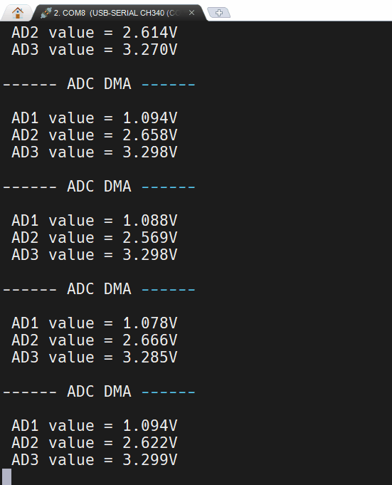
多通道ADC
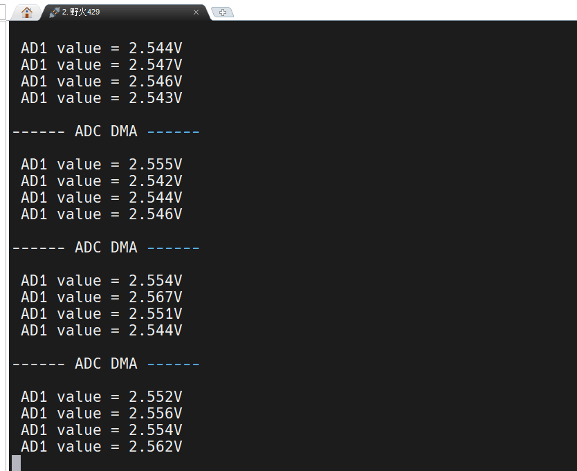
多重ADC
工程文件已上传。


 1381
1381


 被折叠的 条评论
为什么被折叠?
被折叠的 条评论
为什么被折叠?
 到【灌水乐园】发言


