


Arduino - RFID/NFC
Arduino - RFID/NFC
In this tutorial, we are going to learn how to use RFID/NFC with Arduino. The RFID/NFC system includes two components: reader and tag. There are two popular RFID/NFC readers: RC522 and PN532 RFID/NFC reader. This tutorial focuses on RC522 RFID/NFC reader. PN532 RFID/NFC reader will be presented in an upcoming tutorial.
在本教程中,我们将学习如何将RFID / NFC与Arduino一起使用。RFID/NFC系统包括两个组件:读卡器和标签。有两种流行的 RFID/NFC 阅读器:RC522 和 PN532 RFID/NFC 阅读器。本教程重点介绍 RC522 RFID/NFC 阅读器。PN532 RFID/NFC阅读器将在即将到来的教程中介绍。
RC522 RFID/NFC reader (also called RFID-RC522 Module) can:
RC522 RFID/NFC读写器(也称为RFID-RC522模块)可以:
- Read the UID of RFID/NFC tag
读取RFID / NFC标签的UID - Change the UID of RFID/NFC tag (only if the tag is UID-writable)
更改 RFID/NFC 标签的 UID(仅当标签是 UID 可写的时) - Write data to RFID/NFC tag
将数据写入 RFID/NFC 标签 - Read data from RFID/NFC tag
从RFID/NFC标签读取数据
In above capabilities, for Arduino, reading the UID is the most widely-used. This tutorial focuses on reading the UID of RFID/NFC tag. The other will be present in next tutorials
在上述能力中,对于Arduino来说,读取UID是应用最广泛的。本教程重点介绍如何读取RFID/NFC标签的UID。另一个将在下一个教程中出现
Hardware Required 所需硬件
About RFID-RC522 Module 关于RFID-RC522模块
RFID-RC522 Module Pinout RFID-RC522 模块引脚排列
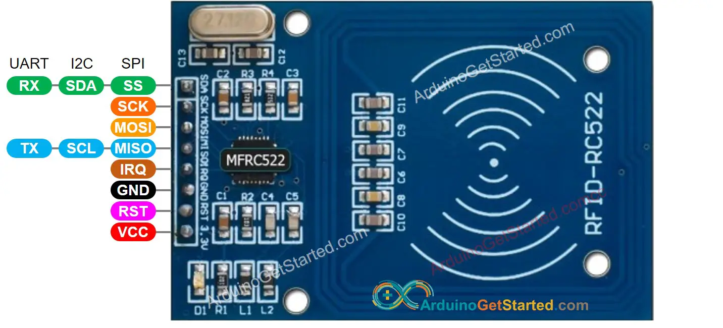
RFID-RC522 has 8 pins, some of them are common pins, the others are shared among three communication modes: SPI, I2C, UART. At a time, only one communication mode can be used. The pin are:
RFID-RC522 有 8 个引脚,其中一些是公共引脚,其他引脚由三种通信模式共享:SPI、I2C、UART。每次只能使用一种通信模式。这些引脚是:
- GND pin: needs to be connected to GND (0V)
GND引脚:需要接GND(0V) - VCC pin: needs to be connected to VCC (3.3)
VCC 引脚:需要连接到 VCC (3.3) - RST pin: is a pin for reset and power-down. When this pin goes low, hard power-down is enabled. On the rising edge, the module is reset.
RST引脚:是用于复位和关断的引脚。当此引脚变为低电平时,使能硬断电。在上升沿上,模块被复位。 - IRQ pin: is an interrupt pin that can alert the microcontroller when RFID tag comes into its vicinity.
IRQ引脚:是一个中断引脚,当RFID标签进入其附近时,可以提醒微控制器。 - MISO/SCL/TX pin: acts as MISO when SPI interface is enabled, acts as SCL when I2C interface is enabled and acts as TX when UART interface is enabled.
MISO/SCL/TX 引脚:在启用 SPI 接口时充当 MISO,在启用 I2C 接口时充当 SCL,在启用 UART 接口时充当 TX。 - MOSI pin: acts as MOSI when SPI interface is enabled.
MOSI引脚:启用SPI接口时充当MOSI。 - SCK pin: acts as SCK when SPI interface is enabled
SCK 引脚:启用 SPI 接口时充当 SCK - SS/SDA/RX pin: acts as SS when SPI interface is enabled, acts as SDA when I2C interface is enabled and acts as RX when UART interface is enabled.
SS/SDA/RX 引脚:在启用 SPI 接口时充当 SS,在启用 I2C 接口时充当 SDA,在启用 UART 接口时充当 RX。
※ NOTE THAT: ※ 注意事项:
-
The order of pins can vary according to manufacturers. ALWAYS use the labels printed on the module. The above image shows the pinout of the module from DIYables manufacturer.
-
引脚的顺序因制造商而异。请务必使用模块上印制的标签。上图显示的是 DIYables 制造商的模块引脚布局。
-
Do not connect VCC pin to 5V pin. This will likely destroy your module.
请勿将 VCC 引脚连接到 5V 引脚。这可能会损坏您的模块。 -
MFRC522 library supports only SPI mode. Therefore, this tutorial uses only SPI communication.
MFRC522库仅支持 SPI 模式。因此,本教程仅使用 SPI 通信。
How RFID/NFC Works RFID/NFC 的工作原理
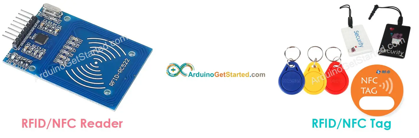
RFID/NFC includes two components: reader and tag.
RFID/NFC 包括两个组件:读取器和标签。
- The reader consists of a radio frequency module and an antenna which generates high frequency electromagnetic field.
读卡器由射频模块和产生高频电磁场的天线组成。 - The tag is usually a passive device, which doesn’t need to have power source. The tag contains a microchip that stores and processes information, and an antenna to receive and transmit a signal. The tag is used to store the information: UID (Unique ID) and data.
标签通常是无源设备,不需要电源。该标签包含一个存储和处理信息的微芯片,以及一个用于接收和传输信号的天线。该标签用于存储信息:UID(唯一 ID)和数据。
To read the information on a tag, the tag must be in close proximity to the reader (does not require the direct line-of-sight). The reading processes:
要读取标签上的信息,标签必须靠近阅读器(不需要直接视线)。阅读过程:
- The reader generates an electromagnetic field which causes electrons to move through the tag’s antenna and subsequently power the chip.
读取器产生电磁场,使电子穿过标签的天线,随后为芯片供电。 - The chip inside the tag then responds by sending the requested information back to the reader in the form of another radio signal.
然后,标签内的芯片以另一种无线电信号的形式将所需信息发送回阅读器。 - The reader detects the signal and transform the signal into data
读取器检测信号并将信号转换为数据 - Arduino reads the data from reader.
Arduino从阅读器读取数据。
Wiring Diagram between RFID-RC522 Module and Arduino RFID-RC522模块与Arduino之间的接线图
The RFID-RC522 Module is designed to operate at a 3.3V level, while the output pins of an Arduino produce a 5V level. So:
RFID-RC522 模块设计为在 3.3V 电平下工作,而 Arduino 的输出引脚产生 5V 电平。所以:
- To be safe, It needs to regulate 5V voltage from Arduino pins to 3.3V before connecting to the RC522 Module
为了安全起见,在连接到 RC522 模块之前,它需要将 Arduino 引脚的 5V 电压调节到 3.3V - To be simple and for the testing purpose, it can connect Arduino pins directly to RC522 Module, but doing so might cause the Arduino to stop working correctly in some cases.
为了简单起见,出于测试目的,它可以将Arduino引脚直接连接到RC522模块,但这样做可能会导致Arduino在某些情况下停止正常工作。
This tutorial provide two different wiring diagrams for both cases:
本教程为这两种情况提供了两种不同的接线图:
- Wiring Diagram between RC522 and Arduino without voltage regulator
RC522和Arduino之间的接线图,不带稳压器

- Wiring Diagram between RC522 and Arduino with voltage regulator
RC522和Arduino之间的接线图,带电压调节器
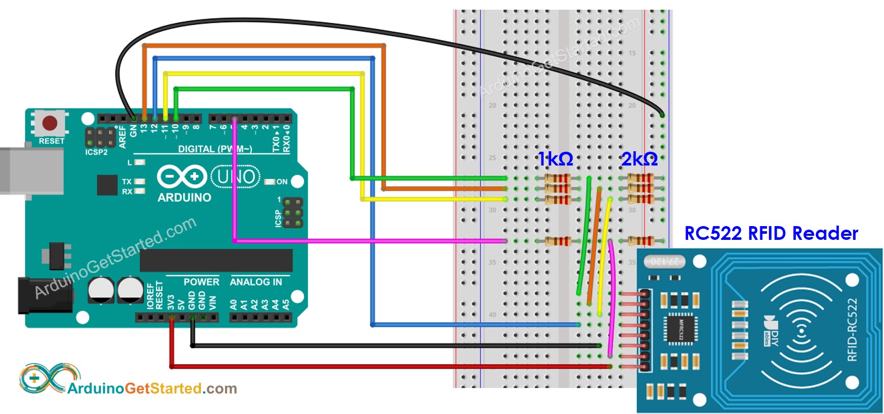
As shown in the wiring diagram above, 1kOhM and 2kOhm pair of resistors are used to regulate 5V to 3.3V. It does not need to adjust the voltage between the Arduino pin and the MISO pin of the RC522 module. However, it is necessary to regulate the voltage between the Arduino pins and the SS, SCK, MOSI, and RST pins of the RC522 module.
如上接线图所示,一对 1kOhM 和 2kOhm 电阻用于将 5V 电压调节为 3.3V。无需调节 Arduino 引脚和 RC522 模块 MISO 引脚之间的电压。但是,有必要调节 Arduino 引脚与 RC522 模块的 SS、SCK、MOSI 和 RST 引脚之间的电压。
Wiring table of RFID/NFC RC522 Module and Arduino RFID/NFC RC522模块和Arduino接线表
| RFID/NFC RC522 无线射频识别/NFC RC522 | Arduino Arduino的 |
|---|---|
| SS | → 10 |
| SCK | → 13 |
| MOSI | → 11 |
| MISO | → 12 |
| IRQ(not connected) IRQ(未连接) | |
| GND | → GND |
| RST | → 5 |
| VCC | → 3.3V |
Arduino RFID/NFC Code Arduino RFID/NFC代码
/*

 * Created by ArduinoGetStarted.com
   *
 * This example code is in the public domain
   *
 * Tutorial page: https://arduinogetstarted.com/tutorials/arduino-rfid-nfc
   */

#include <SPI.h>

#include <MFRC522.h>

#define SS_PIN 10

#define RST_PIN 5

MFRC522 rfid(SS_PIN, RST_PIN);

void setup() {
  Serial.begin(9600);
  SPI.begin(); // init SPI bus
  rfid.PCD_Init(); // init MFRC522

  Serial.println("Tap RFID/NFC Tag on reader");
}

void loop() {
  if (rfid.PICC_IsNewCardPresent()) { // new tag is available
    if (rfid.PICC_ReadCardSerial()) { // NUID has been readed
      MFRC522::PICC_Type piccType = rfid.PICC_GetType(rfid.uid.sak);
      //Serial.print("RFID/NFC Tag Type: ");
      //Serial.println(rfid.PICC_GetTypeName(piccType));

      // print NUID in Serial Monitor in the hex format
      Serial.print("UID:");
      for (int i = 0; i < rfid.uid.size; i++) {
        Serial.print(rfid.uid.uidByte[i] < 0x10 ? " 0" : " ");
        Serial.print(rfid.uid.uidByte[i], HEX);
      }
      Serial.println();

      rfid.PICC_HaltA(); // halt PICC
      rfid.PCD_StopCrypto1(); // stop encryption on PCD
    }
  }
}
Quick Steps 快速步骤
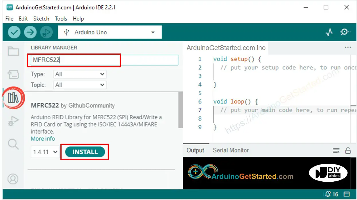
- Navigate to the Libraries icon on the left bar of the Arduino IDE.
导航到 Arduino IDE 左侧栏上的 Libraries 图标。 - Search “MFRC522”, then find the library by GithubCommunity
搜索“MFRC522”,然后通过 GithubCommunity 找到库 - Click Install button to install MFRC522 library.
单击“安装”按钮安装MFRC522库。

- Copy the above code and open with Arduino IDE
复制上面的代码并使用Arduino IDE打开 - Click Upload button on Arduino IDE to upload code to Arduino
单击Arduino IDE上的“上传”按钮,将代码上传到Arduino - Open Serial Monitor 开放式串行监视器
- Tap several RFID/NFC tags on RFID-RC522 module
点击 RFID-RC522 模块上的多个 RFID/NFC 标签 - See UID on Serial Monitor
查看串行监视器上的 UID
Arduino - RFID/NFC - 伺服电机
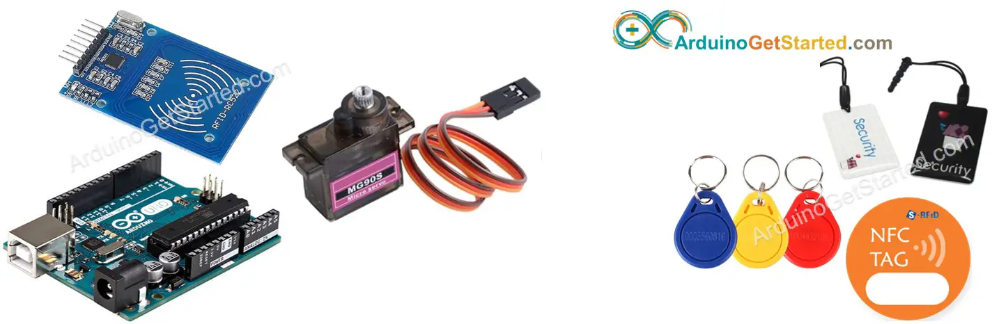
In this tutorial, we are going to learn how to use RFID/NFC tag to control servo motor using Arduino, It works as follows:
在本教程中,我们将学习如何使用 RFID/NFC 标签使用 Arduino 控制伺服电机,其工作原理如下:
- If an authorized tag is tapped, Arduino rotates servo motor to 90°
如果点击授权标签,Arduino 会将伺服电机旋转至 90° - If an authorized tag is tapped again, Arduino rotates servo motor back to 0°
如果再次点击授权标签,Arduino 会将伺服电机旋转回 0° - The above process is repeated infinitely
上述过程无限重复
This can be applied to lock/unlock cabinet, drawer, door, or open/clock the pet feeder…
这可以应用于锁定/解锁橱柜、抽屉、门或打开/时钟宠物喂食器…
About RFID/NFC RC522 Module and Servo Motor 关于RFID/NFC RC522模块和伺服电机
If you do not know about RFID/NFC RC522 Module and Servo Motor (pinout, how it works, how to program …), learn about them in the following tutorials:
如果您不了解 RFID/NFC RC522 模块和伺服电机(引脚排列、工作原理、编程方法等),请在以下教程中了解它们:
- Arduino - RFID/NFC RC522 tutorial
Arduino - RFID/NFC RC522 教程 - Arduino - Servo Motor tutorial
Arduino - 伺服电机教程
How It Works 它是如何工作的
- The UIDs of some RFID/NFC tags are preset in Arduino code
一些RFID / NFC标签的UID在Arduino代码中预设 - User taps an RFID/NFC tag on RFID/NFC reader
用户在 RFID/NFC 阅读器上点击 RFID/NFC 标签 - The reader reads UID from the tag.
读取器从标记中读取 UID。 - Arduino gets the UID from the reader
Arduino从读卡器获取UID - Arduino compares the read UID with the predefined UIDs
Arduino将读取的UID与预定义的UID进行比较 - If the UID is matched with one of the predefined UIDs, Arduino controls servo motor to 90°.
如果 UID 与预定义的 UID 之一匹配,Arduino 将伺服电机控制到 90°。 - If the tag is tapped again, Arduino controls servo motor back to 0°
如果再次点击标签,Arduino将伺服电机控制回0° - This process is repeated infinitely.
这个过程是无限重复的。
Wiring Diagram 接线图
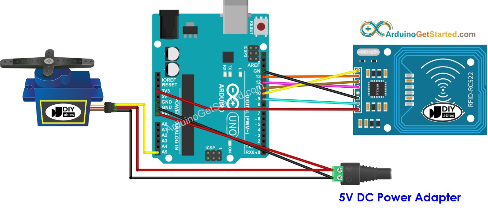
In above wiring diagram, a single 5V addapter supplies power to Arduino directly, to servo motor directly, and RC522 module (indirectly via 3.3V pin of Arduino).
在上面的接线图中,单个 5V addapter 直接向 Arduino 供电,直接向伺服电机供电,RC522 模块(通过 Arduino 的 3.3V 引脚间接供电)。
To simplify the process, the pins of the RC522 module are directly connected to the pins of the Arduino. However, this can cause the Arduino to stop functioning correctly in certain cases as the output pins of the Arduino produce a voltage of 5V, while the pins of the RC522 module function normally at a voltage of 3.3V. Consequently, it is advisable to regulate the voltage between the pins of the Arduino and those of the RC522 module. For further details, please refer to the Arduino - RFID RC522 tutorial. The diagram below depicts how to regulate 5V to 3.3V using resistors:
为了简化流程,RC522模块的引脚直接连接到Arduino的引脚。但是,这可能会导致Arduino在某些情况下停止正常工作,因为Arduino的输出引脚产生5V的电压,而RC522模块的引脚在3.3V的电压下正常工作。因此,建议调节Arduino引脚和RC522模块引脚之间的电压。有关详细信息,请参阅 Arduino - RFID RC522 教程。下图描述了如何使用电阻器调节 5V 至 3.3V:
※ NOTE THAT: ※ 注意事项:
The order of pins can vary according to manufacturers. ALWAYS use the labels printed on the module. The above image shows the pinout of the modules from DIYables manufacturer.
引脚的顺序可能因制造商而异。始终使用印在模块上的标签。上图显示了 DIYables 制造商的模块引脚排列。
Wiring table of RFID/NFC RC522 Module RFID/NFC RC522模块接线表
| RFID/NFC RC522 无线射频识别/NFC RC522 | Arduino Arduino的 |
|---|---|
| SS | → 10 |
| SCK | → 13 |
| MOSI | → 11 |
| MISO | → 12 |
| IRQ(not connected) IRQ(未连接) | |
| GND | → GND |
| RST | → 9 |
| VCC | → 3.3V |
Wiring table of Servo Motor 伺服电机接线表
| Servo Motor 伺服电机 | Arduino Arduino的 | 5V DC Adapter 5V 直流适配器 |
|---|---|---|
| VCC (red) VCC(红色) | → positive →正极 | |
| GND (brown) GND(棕色) | → negative → 负极 | |
| SIG (yellow) SIG(黄色) | → A5 |
Wiring table of 5V DC Adapter 5V直流适配器接线表
| 5V DC Adapter 5V 直流适配器 | Servo Motor 伺服电机 | Arduino Arduino的 |
|---|---|---|
| Positive 阳性 | → VCC | |
| Positive 阳性 | -> Vin ->文 | |
| Negative 阴性 | → GND | |
| Negative 阴性 | → GND |
Arduino Code - Single RFID/NFC Tag Arduino代码 - 单个RFID / NFC标签
/*

 * Created by ArduinoGetStarted.com
   *
 * This example code is in the public domain
   *
 * Tutorial page: https://arduinogetstarted.com/tutorials/arduino-rfid-nfc-servo-motor
   */

#include <SPI.h>

#include <MFRC522.h>

#include <Servo.h>

#define SS_PIN    10

#define RST_PIN   9

#define SERVO_PIN A5

MFRC522 rfid(SS_PIN, RST_PIN);
Servo servo;

byte authorizedUID[4] = {0xFF, 0xFF, 0xFF, 0xFF};
int angle = 0; // the current angle of servo motor

void setup() {
  Serial.begin(9600);
  SPI.begin(); // init SPI bus
  rfid.PCD_Init(); // init MFRC522
  servo.attach(SERVO_PIN);
  servo.write(angle); // rotate servo motor to 0°

  Serial.println("Tap RFID/NFC Tag on reader");
}

void loop() {
  if (rfid.PICC_IsNewCardPresent()) { // new tag is available
    if (rfid.PICC_ReadCardSerial()) { // NUID has been readed
      MFRC522::PICC_Type piccType = rfid.PICC_GetType(rfid.uid.sak);

      if (rfid.uid.uidByte[0] == authorizedUID[0] &&
          rfid.uid.uidByte[1] == authorizedUID[1] &&
          rfid.uid.uidByte[2] == authorizedUID[2] &&
          rfid.uid.uidByte[3] == authorizedUID[3] ) {
        Serial.println("Authorized Tag");

        // change angle of servo motor
        if (angle == 0)
          angle = 90;
        else //if(angle == 90)
          angle = 0;

        // control servo motor arccoding to the angle
        servo.write(angle);
        Serial.print("Rotate Servo Motor to ");
        Serial.print(angle);
        Serial.println("°");
      } else {
        Serial.print("Unauthorized Tag with UID:");
        for (int i = 0; i < rfid.uid.size; i++) {
          Serial.print(rfid.uid.uidByte[i] < 0x10 ? " 0" : " ");
          Serial.print(rfid.uid.uidByte[i], HEX);
        }
        Serial.println();
      }

      rfid.PICC_HaltA(); // halt PICC
      rfid.PCD_StopCrypto1(); // stop encryption on PCD
    }
  }
}
Quick Steps 快速步骤
- Navigate to the Libraries icon on the left bar of the Arduino IDE.
导航到 Arduino IDE 左侧栏上的 Libraries 图标。 - Search “MFRC522”, then find the library by GithubCommunity
搜索“MFRC522”,然后通过 GithubCommunity 找到库 - Click Install button to install MFRC522 library.
单击“安装”按钮安装MFRC522库。
Because UID is usually not printed on RFID/NFC tag, The first step we need to do is to find out the tag’s UID. This can be done by:
因为 UID 通常不会打印在 RFID/NFC 标签上,我们需要做的第一步是找出标签的 UID。这可以通过以下方式完成:
- Copy the above code and open with Arduino IDE
复制上面的代码并使用Arduino IDE打开 - Click Upload button on Arduino IDE to upload code to Arduino
单击Arduino IDE上的“上传”按钮,将代码上传到Arduino - Open Serial Monitor 开放式串行监视器
- Tap an RFID/NFC tag on RFID-RC522 module
点击 RFID-RC522 模块上的 RFID/NFC 标签 - Get UID on Serial Monitor
在串行监视器上获取 UID
Tap RFID/NFC tag on reader Unauthorized Tag with UID: 3A C9 6A CB
点击读卡器上的 RFID/NFC 标签 带 UID 的未经授权的标签:3A C9 6A CB
-
Update UID in the line 20 of the above code. For example, change byte authorizedUID[4] = {0xFF, 0xFF, 0xFF, 0xFF}; TO byte authorizedUID[4] = {0x3A, 0xC9, 0x6A, 0xCB};
更新上述代码第 20 行中的 UID。例如,更改 byte authorizedUID[4] = {0xFF, 0xFF, 0xFF, 0xFF};TO 字节 authorizedUID[4] = {0x3A, 0xC9, 0x6A, 0xCB}; -
Upload the code to Arduino again
再次将代码上传到Arduino -
Tap an RFID/NFC tag on RFID-RC522 module
点击 RFID-RC522 模块上的 RFID/NFC 标签 -
You will see the servo motor rotate to 90°
您将看到伺服电机旋转 90° -
See output on Serial Monitor
查看串行监视器上的输出 -
Tap the same RFID/NFC tag on RFID-RC522 module again
再次点击 RFID-RC522 模块上的相同 RFID/NFC 标签 -
You will see the servo motor rotate to 0°
您将看到伺服电机旋转到 0° -
See output on Serial Monitor
查看串行监视器上的输出
Tap RFID/NFC tag on reader Authorized Tag Rotate Servo Motor to 90° Authorized Tag Rotate Servo Motor to 0°
点击读卡器上的 RFID/NFC 标签 授权标签 将伺服电机旋转至90° 授权标签 将伺服电机旋转至0°
Tap RFID/NFC tag on reader Authorized Tag Rotate Servo Motor to 90° Authorized Tag Rotate Servo Motor to 0° Unauthorized Tag with UID: BD 1E 1D 00
点击读卡器上的 RFID/NFC 标签 授权标签 将伺服电机旋转至90° 授权标签 将伺服电机旋转至0° 带有 UID 的未经授权的标签:BD 1E 1D 00
Arduino Code - Multiple RFID/NFC Tags Arduino代码 - 多个RFID / NFC标签
We can allow multiple RFID/NFC tags to control servo motor. The below code uses two tags as an example.
我们可以允许多个RFID / NFC标签来控制伺服电机。以下代码以两个标签为例。
/*
 * Created by ArduinoGetStarted.com
 *
 * This example code is in the public domain
 *
 * Tutorial page: https://arduinogetstarted.com/tutorials/arduino-rfid-nfc-servo-motor
 */

#include <SPI.h>
#include <MFRC522.h>
#include <Servo.h>

#define SS_PIN    10
#define RST_PIN   9
#define SERVO_PIN A5

MFRC522 rfid(SS_PIN, RST_PIN);
Servo servo;

byte authorizedUID1[4] = {0x3A, 0xC9, 0x6A, 0xCB};
byte authorizedUID2[4] = {0x30, 0x01, 0x8B, 0x15};

int angle = 0; // the current angle of servo motor

void setup() {
  Serial.begin(9600);
  SPI.begin(); // init SPI bus
  rfid.PCD_Init(); // init MFRC522
  servo.attach(SERVO_PIN);
  servo.write(angle); // rotate servo motor to 0°

  Serial.println("Tap RFID/NFC Tag on reader");
}

void loop() {
  if (rfid.PICC_IsNewCardPresent()) { // new tag is available
    if (rfid.PICC_ReadCardSerial()) { // NUID has been readed
      MFRC522::PICC_Type piccType = rfid.PICC_GetType(rfid.uid.sak);

      if (rfid.uid.uidByte[0] == authorizedUID1[0] &&
          rfid.uid.uidByte[1] == authorizedUID1[1] &&
          rfid.uid.uidByte[2] == authorizedUID1[2] &&
          rfid.uid.uidByte[3] == authorizedUID1[3] ) {
        Serial.println("Authorized Tag 1");
        changeServo();
      } else if (rfid.uid.uidByte[0] == authorizedUID2[0] &&
                 rfid.uid.uidByte[1] == authorizedUID2[1] &&
                 rfid.uid.uidByte[2] == authorizedUID2[2] &&
                 rfid.uid.uidByte[3] == authorizedUID2[3] ) {
        Serial.println("Authorized Tag 2");
        changeServo();
      } else {
        Serial.print("Unauthorized Tag with UID:");
        for (int i = 0; i < rfid.uid.size; i++) {
          Serial.print(rfid.uid.uidByte[i] < 0x10 ? " 0" : " ");
          Serial.print(rfid.uid.uidByte[i], HEX);
        }
        Serial.println();
      }

      rfid.PICC_HaltA(); // halt PICC
      rfid.PCD_StopCrypto1(); // stop encryption on PCD
    }
  }
}

void changeServo() {
  // change angle of servo motor
  if (angle == 0)
    angle = 90;
  else //if(angle == 90)
    angle = 0;

  // control servo motor arccoding to the angle
  servo.write(angle);
  Serial.print("Rotate Servo Motor to ");
  Serial.print(angle);
  Serial.println("°");
}


 322
322

 被折叠的 条评论
为什么被折叠?
被折叠的 条评论
为什么被折叠?
 到【灌水乐园】发言


