/*
Test and validation of the circuit.
This sketch will check the I2C communication bus and try to tune the receiver on a given frequency.
ATTENTION:
Please, avoid using the computer connected to the mains during testing. Used just the battery of your computer.
This sketch was tested on ATmega328 based board. If you are not using a ATmega328, please check the pins of your board.
The main advantages of using this sketch are:
1) It is a easy way to check if your circuit is working;
2) You do not need to connect any display device to make your radio works;
3) You do not need connect any push buttons or encoders to change volume and frequency;
4) The Arduino IDE is all you need to check your circuit.
By Ricardo Lima Caratti, 2020.
*/
#include <RDA5807.h>
#define FIX_STATION 10340 //8860 9350 9000 8990 9790 10520 10340
RDA5807 rx;
void setup() {
Serial.begin(115200);
while(!Serial);
delay(500);
if (!checkI2C())
{
Serial.println("\nCheck your circuit!");
while(1);
}
rx.setup();
rx.setVolume(8);
delay(500);
// //****
Serial.print("\nEstacao 106.5MHz");
rx.setFrequency(FIX_STATION); // The frequency you want to select in MHz multiplied by 100.
Serial.print("\nCurrent Channel: ");
Serial.print(rx.getRealChannel());
delay(500);
Serial.print("\nReal Frequency.: ");
Serial.print(rx.getRealFrequency());
Serial.print("\nRSSI: ");
Serial.print(rx.getRssi());
// Mute test
Serial.print("\nAfter 5s device will mute during 3s");
delay(5000);
rx.setMute(true);
delay(3000);
rx.setMute(false);
Serial.print("\nMute test has finished.");
Serial.print("\nEstacao 106.5MHz");
rx.setFrequency(FIX_STATION);
delay(1000);
// // Seek test
// Serial.print("\nSeek station");
// for (int i = 0; i < 10; i++ ) {
// rx.seek(1,0);
// Serial.print("\nReal Frequency.: ");
// Serial.print(rx.getRealFrequency());
// delay(5000);
// }
}
void loop() {
}
/**
* Returns true if device found
*/
bool checkI2C() {
Wire.begin();
byte error, address;
int nDevices;
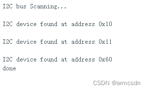
Serial.println("I2C bus Scanning...");
nDevices = 0;
for(address = 1; address < 127; address++ ) {
Wire.beginTransmission(address);
error = Wire.endTransmission();
if (error == 0) {
Serial.print("\nI2C device found at address 0x");
if (address<16) {
Serial.print("0");
}
Serial.println(address,HEX);
nDevices++;
}
else if (error==4) {
Serial.print("\nUnknow error at address 0x");
if (address<16) {
Serial.print("0");
}
Serial.println(address,HEX);
}
}
if (nDevices == 0) {
Serial.println("No I2C devices found\n");
return false;
}
else {
Serial.println("done\n");
return true;
}
}


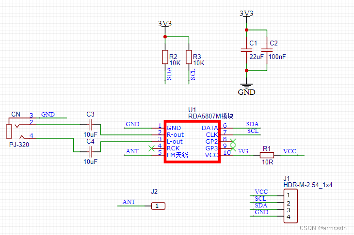
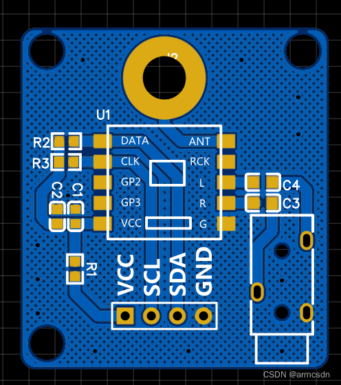
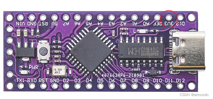
 在尝试使用LGT8F328P-LQFP48MiniEVB开发板调试RDA5807M调频广播模块时,遇到无法接收广播的问题。初步误认为是I2C通信故障,但更换为LQFP32开发板后,模块正常工作。问题根源在于原开发板只有5V电压,而RDA5807M需要1.8到3.3V工作电压,电压不匹配导致故障。解决方法是确保提供正确的电源电压。


 1137
1137


 被折叠的 条评论
为什么被折叠?
被折叠的 条评论
为什么被折叠?
 到【灌水乐园】发言


