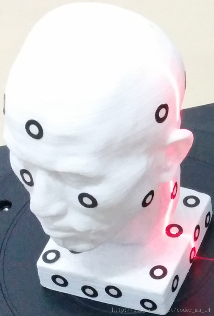
我们有无数种方法可以让扫描仪进行360°扫描
拿我导师的项目来举例


在被测物体上贴上标定点,先扫一次点,然后多次扫描拼接时,保证任意一次扫描均能看见3个以上的点,即可根据点,拼接整个被测物体。
再说一个商业扫描仪
这是一个手持扫描仪


扫描时不需要贴任何的标定点 是的完全不需要!
扫描仪是线激光扫描仪,投射一个红十字和蓝激光,由一个摄像头、激光发射器还有其他传感器组成。
这个扫描仪是极其强大的,我这里只说拼接。
它是如何实现在不贴点的情况下拼接的呢?
可以发现,这个扫描仪后面跟了一个机械臂一样的东西。
没错!这台扫描仪正是利用这个像机械臂一样的装置,获取空间位置,而且精度极高。
我顿时觉得人生好黑暗…怎么什么玩意都做出来了…要我何用…
回来看看我们的破烂转盘扫描仪

为了从不同的镜头重建整个物体,我们需要把定义物体的所有的点设定在同一个坐标系。把初始拍摄点P的坐标定义为P(X, Y, Z),当转盘旋转的时候P点坐标发生改变,新坐标为P(X,Y, Z)。

具体的机械结构设计请参考我的上一篇博客。
Arduino
Arduino代码是最简单的
不过分为两种~(我Arduino比较多)
一、任意角度任意次数扫描代码
int potPin = A0;
int Pos = 0;

void setup() {
  // put your setup code here, to run once:
  pinMode(potPin, INPUT);
  Serial.begin(9600);
}

void loop() {
  // put your main code here, to run repeatedly:
  Pos = analogRead(potPin);
  delay(250);
  Serial.println(Pos);
}
setup 、 loop 和 analogRead请参考我之前的博客
代码详解
第一行给我们看中的端口起一个新名字,只是起一个新名字而已,我们看中的这个端口原来叫做A0,现在叫做potPin,我们还需要知道它是一个模拟口。
第二行初始化一个整型变量Pos,用来保存读到的数据,将来还要把这个Pos告诉电脑上的Processing。这个读数就是Arduino读到的电位器的数值,范围是0-1023。
pinMode定义的是用哪个口,它用来读入还是输出。我们希望A0口也就是potPin这个口是输入口。
所以:pinMode ——我要设置端口 (potPin ——我要用这个端口了 , INPUT ——这个端口负责读入 ); ——一行代码到此为止。
Serial.begin(9600);是设置波特率。
其实想设置多少波特率很随意的,只不过我设置为9600而已,当然你可以设置为115200。
!!!!!!!!!!!!!!!!!!!!!!!!!!!
!但是!如果你并不了解波特率!那就千万不要动这个参数!
!!!!!!!!!!!!!!!!!!!!!!!!!!!
这个参数需要和电脑上Processing上的波特率设置一致。
Pos = analogRead(potPin);
analogRead 、delay请参考我之前的博客
首先执行“=”右边的代码,从potPin也就是A0这个端口读入传感器的数据。然后将这个数据保存在Pos这变量中。
delay(250);
delay是延时函数,也就是说,程序运行到这里之后会暂停,就像等红绿灯一样,等多久呢?250毫秒,就是0.25秒。更深的知识会涉及到晶振等硬件,这里不做阐述,本项目中我们知道它能延时就可以了。
Serial.println(Pos);
现在从传感器中读出的数据被装在Pos中,我们现在将这个参数发送到电脑。
使用println发送,会自动发送\n,叫做转义字符,效果就是,每发一个数据,都会自动换一行。
二、简单步进电机运动代码
int xdir = 13;
int Step = 12;
int xen = 9;

void setup() {
  // put your setup code here, to run once:
  pinMode(xen, OUTPUT);
  pinMode(xdir, OUTPUT);
  pinMode(Step, OUTPUT);
  digitalWrite(xen, LOW);
  digitalWrite(xdir, LOW);
}

void loop() {
  // put your main code here, to run repeatedly:
  digitalWrite(Step, LOW);
  delay(10);
  digitalWrite(Step, HIGH);
  delay(10);
}
使用的电机驱动是:ZUM SCAN Shield

使用4线步进电机,这里不对步进电机做详细阐述。
digitalWrite(Step, LOW);
delay(10);
digitalWrite(Step, HIGH);
delay(10);
是给脉冲的意思。如果想加快转速,只需调低delay的参数。
那么digitalWrite又是什么意思呢?
在配置pinMode之后,它可以输出数字信号。那么数字信号和模拟信号又有什么区别?
可以自己百度两个关键词,一个就是数字信号模拟信号,还有一个是占空比。
Processing
一、导包&全局变量初始化
import processing.serial.*;
import processing.opengl.*;
import SimpleOpenNI.*;
import kinectOrbit.*;
//Init Orbit and OpenNI Class.
KinectOrbit myOrbit;
SimpleOpenNI kinect;
//Serial data.
Serial myPort;
boolean serial = true;
//!
String turnTableAngle = "0";
int turnAngle = 0;
float Angle = 0;
//!
//Init pointClouds and ArrayList with clolors.
ArrayList<PVector> scanPoints = new ArrayList<PVector>();//pointCloud
ArrayList<PVector> scanColors = new ArrayList<PVector>();//obj color
ArrayList<PVector> objectPoints = new ArrayList<PVector>();//pointCloud
ArrayList<PVector> objectColors = new ArrayList<PVector>();//obj color

//Height
float baseHeight  = -180;
float modelWidth  = 1000;
float modelHeight = 1000;
PVector axis = new PVector(0, baseHeight, 1200);

int scanLines = 300;
int scanRes   = 1;  //high ppx
boolean scanning = false;
boolean arrived  = false;
float[] shotNumber = new float[30];
int currentShot = 0;

int dataNum = 1;
我们需要4个库,分别是Processing自带的serial和opengl库,以及Kinect需要的SimpleOpenNI库,Kinect摄像机库kinectOrbit。
KinectOrbit myOrbit;
SimpleOpenNI kinect;
Serial myPort;
声明三个类。
boolean serial = true;
是否允许和Arduino通信的boolean型变量。
String turnTableAngle = “0”;
int turnAngle = 0;
float Angle = 0;
用于获得转盘旋转角度的变量。
ArrayList< PVector > scanPoints = new ArrayList< PVector >();
ArrayList< PVector > scanColors = new ArrayList< PVector >();
开辟动态数组,用于储存当前扫描到的点云,实时的。
ArrayList< PVector > objectPoints = new ArrayList< PVector >();
ArrayList< PVector > objectColors = new ArrayList< PVector >();
开辟动态数组,用于储存已经保存的点云,不动的。
float baseHeight = -180;
float modelWidth = 1000;
float modelHeight = 1000;
PVector axis = new PVector(0, baseHeight, 1200);
限定Kinect的扫描范围。以kinect下方180的地方为底,宽1000,高1000,深1200。
int scanLines = 300;
扫描宽度。可以理解为有300个线激光排排坐。
int scanRes = 1;
不跳过任何一个点(高精度)。
boolean scanning = false;
boolean arrived = false;
开始扫描。
float[] shotNumber = new float[30];
int currentShot = 0;
最大扫描次数。
当前扫描次数。
int dataNum = 1;
导出的文件名。
二、setup()函数
public void setup()
{
  size(800, 600, OPENGL);

  //Init orbit
  myOrbit = new KinectOrbit(this, 0, "kinect");
  myOrbit.drawCS(true);
  myOrbit.drawGizmo(true);
  myOrbit.setCSScale(200);
  myOrbit.drawGround(true);

  //Init SimpleOpenNI
  kinect = new SimpleOpenNI(this);
  kinect.setMirror(false);
  kinect.enableDepth();
  kinect.enableRGB();
  kinect.alternativeViewPointDepthToImage();

  //Serial
  if(serial) {
    String portName = Serial.list()[0];
    myPort = new Serial(this, portName, 9600);
    //!
    myPort.bufferUntil('\n');
    //!
  }
}
size(800, 600, OPENGL);
设置窗口x y是800*600像素,启用OPENGL深度显示。
myOrbit = new KinectOrbit(this, 0, “kinect”);
myOrbit.drawCS(true);
myOrbit.drawGizmo(true);
myOrbit.setCSScale(200);
myOrbit.drawGround(true);
初始化Kinect Orbit库。
kinect = new SimpleOpenNI(this);
kinect.setMirror(false);
kinect.enableDepth();
kinect.enableRGB();
kinect.alternativeViewPointDepthToImage();
初始化SimpleOpenNI库。
特别说一下最后一个:alternativeViewPointDepthToImage()方法。
这个方法会调用Kinect自带的标定功能,让彩色图像和深度图像完美结合。
if(serial) {
String portName = Serial.list()[0];
myPort = new Serial(this, portName, 9600);
//!
myPort.bufferUntil(‘\n’);
//!
}
和Arduino进行通信,接收角度值。
String portName = Serial.list()[0];
获得PC——USB——Arduino的端口。
myPort = new Serial(this, portName, 9600);
波特率9600。
myPort.bufferUntil(‘\n’);
当接收到\n这个转义字符时,标志着一个数据的收发结束。
三、draw()函数
public void draw()
{
  kinect.update();
  background(0);
  myOrbit.pushOrbit(this);  //Start Orbit
  drawPointCloud(1);
  //!!!!!
  updateObject(scanLines, scanRes);
  //!!!!!
  drawObjects();
  drawBoundingBox();
  kinect.drawCamFrustum();
  myOrbit.popOrbit(this);
}
kinect.update();
background(0);
刷新一下Kinect再刷新一下整个窗口。
myOrbit.pushOrbit(this);
开始绘制摄像机模型。
drawPointCloud(1);
显示实时点云,不跳过点。跳过的话,把1改大。
updateObject(scanLines, scanRes);
核心。
选择点云模型。保证被扫描到的点在限制范围之内。
drawObjects();
同时显示已经保存的点和实时情况下的点。
drawBoundingBox();
绘制扫描范围
myOrbit.popOrbit(this);
关闭Orbit


 本文介绍了一种实现360°物体扫描的方法,包括使用带有标定点的手持扫描仪和通过机械臂获取空间位置信息的技术。文中还详细讲解了Arduino和Processing的编程代码,展示了如何控制扫描仪进行不同角度的扫描,并处理获取的数据。


 被折叠的 条评论
为什么被折叠?


