


目录
1 概述
CPU虚拟化都需要做哪些事情?
参考连接:Xen and the Art of Virtualization![]() https://www.cl.cam.ac.uk/research/srg/netos/papers/2003-xensosp.pdf
https://www.cl.cam.ac.uk/research/srg/netos/papers/2003-xensosp.pdf
- CPU Protection Guest OS must run at a lower privilege level than Xen.
- Exceptions Guest OS must register a descriptor table for exception handlers with Xen. Aside from page faults, the handlers remain the same
- System Calls Guest OS may install a ‘fast’ handler for system calls, allowing direct calls from an application into its guest OS and avoiding indirecting through Xen on every call.
- Interrupts Hardware interrupts are replaced with a lightweight event system.
- Time Each guest OS has a timer interface and is aware of both ‘real’ and ‘virtual’ time.
以上是XEN在CPU虚拟化中列出的事项,虽然与KVM实现不同,但是,这些大概就是CPU虚拟化中需要实现的部分。当然,XEN与KVM实现不同,所以其中的System Calls可以归入CPU Protection中,毕竟系统调用的目的就是执行特权指令。
2 VMX
参考文档中Xen and the Art of Virtualization![]() https://www.cl.cam.ac.uk/research/srg/netos/papers/2003-xensosp.pdf
https://www.cl.cam.ac.uk/research/srg/netos/papers/2003-xensosp.pdf
In order to protect the hypervisor from OS misbehavior (and domains from one another) guest OSes must be modified to run at a lower privilege level.
VMM需要有能力保留对资源的控制权,这些资源包括:processor resources, physical memory, interrupt management, and I/O。 为此Intel为cpu引入了vmx,即virutual machine extensions;
参考Intel手册,23.3 INTRODUCTION TO VMX OPERATION;
Processor support for virtualization is provided by a form of processor operation called VMX operation. There are two kinds of VMX operation: VMX root operation and VMX non-root operation. In general, a VMM will run in VMX root operation and guest software will run in VMX non-root operation. Transitions between VMX root operation and VMX non-root operation are called VMX transitions. There are two kinds of VMX transitions. Transitions into VMX non-root operation are called VM entries. Transitions from VMX non-root operation to VMX root operation are called VM exits.
Processor behavior in VMX non-root operation is restricted and modified to facilitate virtualization. Instead of their ordinary operation, certain instructions (including the new VMCALL instruction) and events cause VM exits to the VMM. Because these VM exits replace ordinary behavior, the functionality of software in VMX non-root operation is limited. It is this limitation that allows the VMM to retain control of processor resources.
vmx引入了root和non-root两种模式,让VMM运行在root模式下,Guest运行在non-root模式下;VMM可以通过vmx的配置让Guest在特定条件下VM-Exit,接管CPU,进而实现对资源的控制。
2.1 Entry & Exit
引用自Intel手册:
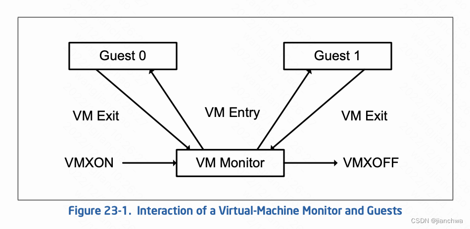
- Software enters VMX operation by executing a VMXON instruction. vmxon指令让CPU进入vmx root operations模式;
- Using VM entries, a VMM can then enter guests into virtual machines (one at a time). The VMM effects VM entry using instructions VMLAUNCH and VMRESUME; it regains control using VM exits. VMM通过vmlaunch和vmresume指令将CPU控制权转交给Guest OS
- VM exits transfer control to an entry point specified by the VMM. The VMM can take action appropriate to the cause of the VM exit and can then return to the virtual machine using a VM entry. VMM可以通过特定配置控制Guest何时VM-exit,进而重新获得CPU控制权;
- Eventually, the VMM may decide to shut itself down and leave VMX operation. It does so by executing the VMXOFF instruction.
本小节,我们将主要关注,在执行vm-entry和vm-exit时,CPU上下文是如何保存和切换的。
vmx引入了一个vmcs,即Virtual-machine Control Data Structure,用来保存一个vm的控制信息;VMM就是通过vmcs实现的对Guest的控制;其中主要保存了如下信息:
- Guest-state area. Processor state is saved into the guest-state area on VM exits and loaded from there on VM entries.
- Host-state area. Processor state is loaded from the host-state area on VM exits.
- VM-execution control fields. These fields control processor behavior in VMX non-root operation. They determine in part the causes of VM exits.
- VM-exit control fields. These fields control VM exits.
- VM-entry control fields. These fields control VM entries.
- VM-exit information fields. These fields receive information on VM exits and describe the cause and the nature of VM-exit;
vmptrld指令用于设置current vmcs,之后,可以通过vmlaunch、vmresume、vmread、vmwrite对这个vmcs进行操作;
vmcs由VMM申请,每个vcpu一个,参考代码alloc_vmcs_cpu()
涉及到上下文信息的包括 Intel手册 24.3 ORGANIZATION OF VMCS DATA,
- Guest-state area. Processor state is saved into the guest-state area on VM exits and loaded from there on VM entries.
- Host-state area. Processor state is loaded from the host-state area on VM exits.
我看下,Guest-state和Host-state area中,与上下文相关的信息,都包括哪些;
Guest-state:
- Control registers CR0, CR3, and CR4 (64 bits each; 32 bits on processors that do not support Intel 64 archi- tecture).
- RSP, RIP, and RFLAGS
Host-state
- CR0, CR3, and CR4 (64 bits each; 32 bits on processors that do not support Intel 64 architecture).
- RSP and RIP
其中,并没有rdi/rsi/rdx/rcs等通用寄存器;
vcpu_run()
  -> vcpu_enter_guest()
    -> kvm_x86_ops->run(vcpu);
      -> vmx_vcpu_run()
	     ---
	vmx->fail = __vmx_vcpu_run(vmx, (unsigned long *)&vcpu->arch.regs,
				   vmx->loaded_vmcs->launched);
		 ---

ENTRY(__vmx_vcpu_run)
	push %_ASM_BP
	mov  %_ASM_SP, %_ASM_BP

	push %r15
	push %r14
	push %r13
	push %r12
	push %_ASM_BX

	push %_ASM_ARG2

	/* Copy @launched to BL, _ASM_ARG3 is volatile. */
	mov %_ASM_ARG3B, %bl

	/* Adjust RSP to account for the CALL to vmx_vmenter(). */
	lea -WORD_SIZE(%_ASM_SP), %_ASM_ARG2
	call vmx_update_host_rsp

	/* Load @regs to RAX. */
	mov (%_ASM_SP), %_ASM_AX

	/* Check if vmlaunch or vmresume is needed */
	cmpb $0, %bl

	/* Load guest registers.  Don't clobber flags. */
	mov VCPU_RBX(%_ASM_AX), %_ASM_BX
	mov VCPU_RCX(%_ASM_AX), %_ASM_CX
	mov VCPU_RDX(%_ASM_AX), %_ASM_DX
	mov VCPU_RSI(%_ASM_AX), %_ASM_SI
	mov VCPU_RDI(%_ASM_AX), %_ASM_DI
	mov VCPU_RBP(%_ASM_AX), %_ASM_BP
#ifdef CONFIG_X86_64
	mov VCPU_R8 (%_ASM_AX),  %r8
	mov VCPU_R9 (%_ASM_AX),  %r9
	mov VCPU_R10(%_ASM_AX), %r10
	mov VCPU_R11(%_ASM_AX), %r11
	mov VCPU_R12(%_ASM_AX), %r12
	mov VCPU_R13(%_ASM_AX), %r13
	mov VCPU_R14(%_ASM_AX), %r14
	mov VCPU_R15(%_ASM_AX), %r15
#endif
	/* Load guest RAX.  This kills the vmx_vcpu pointer! */
	mov VCPU_RAX(%_ASM_AX), %_ASM_AX

	/* Enter guest mode */
	call vmx_vmenter

	/* Jump on VM-Fail. */
	jbe 2f

	/* Temporarily save guest's RAX. */
	push %_ASM_AX

	/* Reload @regs to RAX. */
	mov WORD_SIZE(%_ASM_SP), %_ASM_AX

	/* Save all guest registers, including RAX from the stack */
	__ASM_SIZE(pop) VCPU_RAX(%_ASM_AX)
	mov %_ASM_BX,   VCPU_RBX(%_ASM_AX)
	mov %_ASM_CX,   VCPU_RCX(%_ASM_AX)
	mov %_ASM_DX,   VCPU_RDX(%_ASM_AX)
	mov %_ASM_SI,   VCPU_RSI(%_ASM_AX)
	mov %_ASM_DI,   VCPU_RDI(%_ASM_AX)
	mov %_ASM_BP,   VCPU_RBP(%_ASM_AX)
#ifdef CONFIG_X86_64
	mov %r8,  VCPU_R8 (%_ASM_AX)
	mov %r9,  VCPU_R9 (%_ASM_AX)
	mov %r10, VCPU_R10(%_ASM_AX)
	mov %r11, VCPU_R11(%_ASM_AX)
	mov %r12, VCPU_R12(%_ASM_AX)
	mov %r13, VCPU_R13(%_ASM_AX)
	mov %r14, VCPU_R14(%_ASM_AX)
	mov %r15, VCPU_R15(%_ASM_AX)
#endif
	...

	/* "POP" @regs. */
	add $WORD_SIZE, %_ASM_SP
	pop %_ASM_BX

	pop %r12
	pop %r13
	pop %r14
	pop %r15
	pop %_ASM_BP
	ret

	/* VM-Fail.  Out-of-line to avoid a taken Jcc after VM-Exit. */
2:	mov $1, %eax
	jmp 1b
ENDPROC(__vmx_vcpu_run)
VMM的寄存器保存在了栈里;
Guest OS的寄存器则保存在了
struct kvm_vcpu_arch {
	unsigned long regs[NR_VCPU_REGS];
	...
};
2.2 拦截
vmx都可以拦截vmx non-root operation时的那些操作或者事件?
这里可参考APPENDIX C VMX BASIC EXIT REASONS,下面选择几个关键的:
- External interrupt. An external interrupt arrived and the “external-interrupt exiting” VM-execution control was 1.
- CPUID. Guest software attempted to execute CPUID.
- HLT. Guest software attempted to execute HLT and the “HLT exiting” VM-execution control was 1.
- INVD. Guest software attempted to execute INVD.
- INVLPG. Guest software attempted to execute INVLPG and the “INVLPG exiting” VM-execution control was 1.
- RDTSC. Guest software attempted to execute RDTSC and the “RDTSC exiting” VM-execution control was 1.
- Control-register accesses. Guest software attempted to access CR0, CR3, CR4, or CR8 using CLTS, LMSW, or MOV CR and the VM-execution control fields indicate that a VM exit should occur
- I/O instruction. Guest software attempted to execute an I/O instruction, The“useI/Obitmaps”VM-execution contro lwas 1 and a bit in the I/O bitmap associated with one of the ports accessed by the I/O instruction was 1.
- RDMSR / WRMSR
- EPT violation. An attempt to access memory with a guest-physical address was disallowed by the configuration of the EPT paging structures.
- EPT misconfiguration. An attempt to access memory with a guest-physical address encountered a misconfigured EPT paging-structure entry.
注:EPT misconfiguration用于拦截Guest对MMIO的读写
3 中断虚拟化
3.1 中断处理
3.1.1 IDT
The Interrupt Descriptor Table (IDT) is a binary data structure specific to the IA-32 and x86-64 architectures. It is the Protected Mode and Long Mode counterpart to the Real Mode Interrupt Vector Table (IVT) telling the CPU where the Interrupt Service Routines (ISR) are located (one per interrupt vector)
x86架构下,IDT如何设置?参考代码:
start_secondary()
  -> cpu_init()
    -> load_current_idt()
      -> load_idt((const struct desc_ptr *)&idt_descr);

struct desc_ptr idt_descr __ro_after_init = {
	.size		= (IDT_ENTRIES * 2 * sizeof(unsigned long)) - 1,
	.address	= (unsigned long) idt_table,
};
idt_table的初始化,参考函数:
start_kernel()
  -> init_IRQ()
    -> x86_init.irqs.intr_init()
	  -> native_init_IRQ()
	    -> idt_setup_apic_and_irq_gates()

void __init idt_setup_apic_and_irq_gates(void)
{
	int i = FIRST_EXTERNAL_VECTOR;
	void *entry;

	idt_setup_from_table(idt_table, apic_idts, ARRAY_SIZE(apic_idts), true);

	for_each_clear_bit_from(i, system_vectors, FIRST_SYSTEM_VECTOR) {
		entry = irq_entries_start + 8 * (i - FIRST_EXTERNAL_VECTOR);
		set_intr_gate(i, entry);
	}

#ifdef CONFIG_X86_LOCAL_APIC
	for_each_clear_bit_from(i, system_vectors, NR_VECTORS) {
		set_bit(i, system_vectors);
		set_intr_gate(i, spurious_interrupt);
	}
#endif
}

这个函数首先将apic_idts里面的内容设置进idt_table,里面的我们比较常见的参考以下:
static const __initconst struct idt_data apic_idts[] = {
#ifdef CONFIG_SMP
	INTG(RESCHEDULE_VECTOR,		reschedule_interrupt),
	INTG(CALL_FUNCTION_VECTOR,	call_function_interrupt),
	INTG(CALL_FUNCTION_SINGLE_VECTOR, call_function_single_interrupt),
#endif

#ifdef CONFIG_X86_LOCAL_APIC
	INTG(LOCAL_TIMER_VECTOR,	apic_timer_interrupt),
	INTG(X86_PLATFORM_IPI_VECTOR,	x86_platform_ipi),
	...
};

之后,对于FIRST_SYSTEM_VECTOR以下的,全部设置为以下,其函数入口为common_interrupt,
外部中断的入口就是这,
ENTRY(irq_entries_start)
    vector=FIRST_EXTERNAL_VECTOR
    .rept (FIRST_SYSTEM_VECTOR - FIRST_EXTERNAL_VECTOR)
	UNWIND_HINT_IRET_REGS
	pushq	$(~vector+0x80)			/* Note: always in signed byte range */
	jmp	common_interrupt
	.align	8
	vector=vector+1
    .endr
END(irq_entries_start)
在CPU处理中断的过程中,其需要知道irq vector,然后依据此vector跳转到对应的处理函数;
3.1.2 vector管理
x86架构下,每个CPU有256个vector,其中前32个是reserve给系统的trap、fault和abort的,参考连接:Exceptions - OSDev Wikihttps://wiki.osdev.org/Exceptions
还有一个部分,也被reserve了,比如:
#define ERROR_APIC_VECTOR		0xfe
#define RESCHEDULE_VECTOR		0xfd
#define CALL_FUNCTION_VECTOR		0xfc
#define CALL_FUNCTION_SINGLE_VECTOR	0xfb
#define THERMAL_APIC_VECTOR		0xfa
#define THRESHOLD_APIC_VECTOR		0xf9
#define REBOOT_VECTOR			0xf8
留给我们可以自由申请的,通过irq_matrix维护了起来;参考代码:
allocate_vector()
---
	vector = irq_matrix_alloc(vector_matrix, dest, resvd, &cpu);
	if (vector > 0)
		apic_update_vector(irqd, vector, cpu);
		---
			struct irq_desc *desc = irq_data_to_desc(irqd);
			per_cpu(vector_irq, newcpu)[newvec] = desc;
		---
---

在申请vector的时候,会选择一个使用vector最少的CPU
irq_matrix_alloc()
  -> matrix_find_best_cpu()
	 ---
	for_each_cpu(cpu, msk) {
		cm = per_cpu_ptr(m->maps, cpu);

		if (!cm->online || cm->available <= maxavl)
			continue;

		best_cpu = cpu;
		maxavl = cm->available;
	}
	return best_cpu;
	 ---

选择好CPU之后,会将对应的irq desc安装到该CPU的对应slot上,
在发生IRQ时,会依据vector获取irq desc,并获取对应的action
do_IRQ()
---
	unsigned vector = ~regs->orig_ax;

	entering_irq();
	desc = __this_cpu_read(vector_irq[vector]);
	handle_irq(desc, regs);
	exiting_irq();
---
3.1.3 MSI
Interrupts Delivery in a Multi-host Environmen![]() https://www3.cs.stonybrook.edu/~live3/files/pcie-interrupt-delivery.pdf这个连接里很好的说明了,MSI机制,下面引用里面的一些说法。
https://www3.cs.stonybrook.edu/~live3/files/pcie-interrupt-delivery.pdf这个连接里很好的说明了,MSI机制,下面引用里面的一些说法。
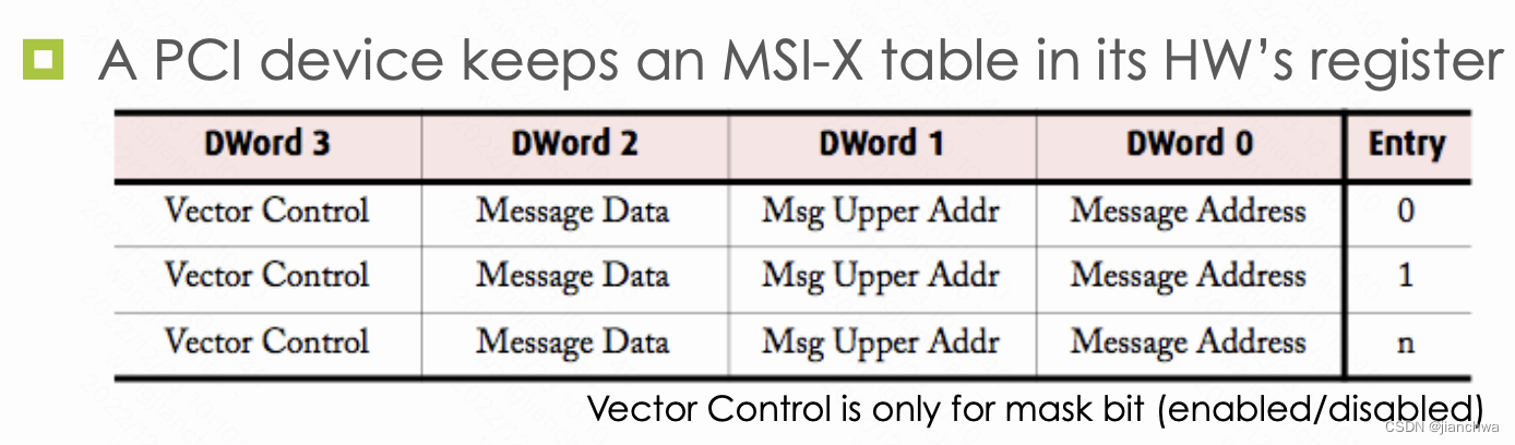
With MSI/MSI-X, everything in PCIe boils down to PCIe read/write
- A device
- Signals interrupt to its host using MSI address (write from the bus to the MSI area, interpreted by the chipset.)
- DMA read/write data to host’s memory
- A host
- Read/write its memory
- Configure its devices using memory-mapped IO
MSI的addr和data的格式为:

其中有两个关键信息,CPU ID和Interrupt Vector;设备是怎么知道这两个信息的呢?
参考如下代码:
pci_alloc_irq_vectors_affinity()
  -> __pci_enable_msix_range()
	-> __pci_enable_msix()
	  -> msix_capability_init()
	    -> pci_msi_setup_msi_irqs()
		  -> msi_domain_alloc_irqs()
	        -> __irq_domain_alloc_irqs()
	           -> irq_domain_alloc_irqs_hierarchy()
	             -> x86_vector_alloc_irqs()
	               -> assign_irq_vector_policy()
	                 -> assign_irq_vector()
	                   -> assign_vector_locked()
	                     -> allocate_vector()
		    -> irq_domain_activate_irq()
	          -> __irq_domain_activate_irq()
			    -> msi_domain_activate()
				  -> irq_chip_write_msi_msg()
					-> pci_msi_domain_write_msg()
  					  -> __pci_write_msi_msg()

__pci_write_msi_msg()
---
		int pos = dev->msi_cap;
		u16 msgctl;

		pci_read_config_word(dev, pos + PCI_MSI_FLAGS, &msgctl);
		msgctl &= ~PCI_MSI_FLAGS_QSIZE;
		msgctl |= entry->msi_attrib.multiple << 4;
		pci_write_config_word(dev, pos + PCI_MSI_FLAGS, msgctl);

		pci_write_config_dword(dev, pos + PCI_MSI_ADDRESS_LO,
				       msg->address_lo);
		if (entry->msi_attrib.is_64) {
			pci_write_config_dword(dev, pos + PCI_MSI_ADDRESS_HI,
					       msg->address_hi);
			pci_write_config_word(dev, pos + PCI_MSI_DATA_64,
					      msg->data);
		} else {
			pci_write_config_word(dev, pos + PCI_MSI_DATA_32,
					      msg->data);
		}

---

msg是在下面的函数构造的
irq_msi_compose_msg()
---
	msg->address_lo =
		MSI_ADDR_BASE_LO |
		((apic->irq_dest_mode == 0) ?
			MSI_ADDR_DEST_MODE_PHYSICAL :
			MSI_ADDR_DEST_MODE_LOGICAL) |
		MSI_ADDR_REDIRECTION_CPU |
		MSI_ADDR_DEST_ID(cfg->dest_apicid);

	msg->data =
		MSI_DATA_TRIGGER_EDGE |
		MSI_DATA_LEVEL_ASSERT |
		MSI_DATA_DELIVERY_FIXED |
		MSI_DATA_VECTOR(cfg->vector);

---
3.2 PIC及其虚拟化
PIC,Programmable Interrupt Controller,即8259,可参考资料:
8259 PIC - OSDev Wikihttps://wiki.osdev.org/8259_PIC8259A PROGRAMMABLE INTERRUPT CONTROLLER
![]() https://pdos.csail.mit.edu/6.828/2017/readings/hardware/8259A.pdf通常将两块8259A如下图连接起来:
https://pdos.csail.mit.edu/6.828/2017/readings/hardware/8259A.pdf通常将两块8259A如下图连接起来:

Each of the two 8259 PICs in modern systems have 8 inputs. When any of the inputs is raised, the PIC sets a bit internally telling one of the inputs needs servicing. It then checks whether that channel is masked or not, and whether there's an interrupt already pending. If the channel is unmasked and there's no interrupt pending, the PIC will raise the interrupt line. On the slave, this feeds IRQ 2 to the master, and the master is connected to the processor interrupt line.
When the processor accepts the interrupt, the master checks which of the two PICs is responsible for answering, then either supplies the interrupt number to the processor, or asks the slave to do so. The PIC that answers looks up the "vector offset" variable stored internally and adds the input line to form the requested interrupt number. After that the processor will look up the interrupt address and act accordingly (see Interrupts for more details).
上文中提到的vector offset,通过IO Port配置进去的,具体方法列出的链接中有。
综上,PIC的工作方式,大致上分为三步:
- 外设在某条irq line上输出;
- PIC通知CPU
- CPU从PIC获取中断的vector,然后调用IDT中对应vector的处理函数
那么如何在软件上模拟这些行为?
注:为什么要模拟?对于Fully Virtualization,VMM必须模拟设备的所有的行为;PIC作为一种设备,自然也需要模拟,比如vector offset的配置和使用
外设设置irq line,PIC通知CPU
kvm_pic_set_irq()
  -> pic_set_irq1()
	 ---
		mask = 1 << irq;
		/*
		 * edge triggered
         *
		 * -------.   .--->
		 *        |   |
		 *        '---'
		 *----------------------
		 */
		if (level) {
			if ((s->last_irr & mask) == 0) {
				ret = !(s->irr & mask);
				s->irr |= mask; // Interrupt Request Register
			}
			s->last_irr |= mask;
		} else
			s->last_irr &= ~mask;
	 ---
  -> pic_update_irq()
	 ---
		irq2 = pic_get_irq(&s->pics[1]);
		if (irq2 >= 0) {
			/*
			 * if irq request by slave pic, signal master PIC
			 */
			pic_set_irq1(&s->pics[0], 2, 1);
			pic_set_irq1(&s->pics[0], 2, 0);
		}
		irq = pic_get_irq(&s->pics[0]);
		pic_irq_request(s->kvm, irq >= 0); // set wakeup_needed if needed
	 ---
  -> pic_unlock()
	 ---
	if (wakeup) {
		kvm_for_each_vcpu(i, vcpu, s->kvm) {
			if (kvm_apic_accept_pic_intr(vcpu)) {
				kvm_make_request(KVM_REQ_EVENT, vcpu);
				kvm_vcpu_kick(vcpu);
				return;
			}
		}
	}
	 ---
被中断的CPU读取irq vector,
vcpu_enter_guest()
  -> inject_pending_event()
	-> kvm_cpu_get_interrupt()
	  -> kvm_cpu_get_extint()
	    -> kvm_pic_read_irq()
---
	pic_lock(s);
	irq = pic_get_irq(&s->pics[0]);
	if (irq >= 0) {
		if (irq == 2) {
			irq2 = pic_get_irq(&s->pics[1]);
			intno = s->pics[1].irq_base + irq2;
			irq = irq2 + 8;
		} else
			intno = s->pics[0].irq_base + irq;
	} else {
		/*
		 * spurious IRQ on host controller
		 */
		irq = 7;
		intno = s->pics[0].irq_base + irq;
	}
	pic_unlock(s);
	return intno;
---

这里的irq_base就是这个PIC的vector offset,它的配置是通过对对应端口的写完成的
配置代码可以参考:
#define PIC1		0x20		/* IO base address for master PIC */
#define PIC2		0xA0		/* IO base address for slave PIC */
#define PIC1_COMMAND	PIC1
#define PIC1_DATA	(PIC1+1)
#define PIC2_COMMAND	PIC2
#define PIC2_DATA	(PIC2+1)

#define ICW1_ICW4	0x01		/* ICW4 (not) needed */
#define ICW1_INIT	0x10		/* Initialization - required! */
/*
arguments:
	offset1 - vector offset for master PIC
		vectors on the master become offset1..offset1+7
	offset2 - same for slave PIC: offset2..offset2+7
*/
void PIC_remap(int offset1, int offset2)
{
	unsigned char a1, a2;

	a1 = inb(PIC1_DATA);                        // save masks
	a2 = inb(PIC2_DATA);

	outb(PIC1_COMMAND, ICW1_INIT | ICW1_ICW4);  // reset
	io_wait();
	outb(PIC2_COMMAND, ICW1_INIT | ICW1_ICW4);  // reset
	io_wait();
	outb(PIC1_DATA, offset1);                 // ICW2: Master PIC vector offset
	io_wait();
	outb(PIC2_DATA, offset2);                 // ICW2: Slave PIC vector offset
	io_wait();
	....
}
pic_ioport_write()
---
	addr &= 1;
	if (addr == 0) { // command port 0x20 or 0xa0
		if (val & 0x10) {
			s->init4 = val & 1;
			...
			kvm_pic_reset(s); // set init_state to '1'
		}
	} else // data port 0x21 or 0xa1
		switch (s->init_state) {
		case 1:
			s->irq_base = val & 0xf8;
			s->init_state = 2;
			break;
			...
		}
---
3.3 APIC及其虚拟化
3.3.1 APIC
APIC,包括lapic和ioapic,如下图,解决了多核场景下的中断分发问题;
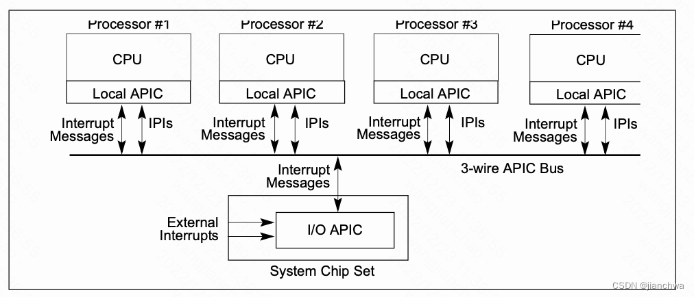
在MSI/MIS-X,引入之后,IOAPIC变得没有必要,设备通过对lapic的pci写事务触发中断;
Reducing Interrupt Latency Through the Use of Message Signaled Interrupts![]() https://www.intel.com/content/dam/www/public/us/en/documents/white-papers/msg-signaled-interrupts-paper.pdfExternal Interrupts in the x86 system. Part 1. Interrupt controller evolution / HabrThis article is about the interrupt delivery process from external devices in the x86 system. It tries to answer questions such as: What is PIC and what is it for? What is APIC and what is it for?...
https://www.intel.com/content/dam/www/public/us/en/documents/white-papers/msg-signaled-interrupts-paper.pdfExternal Interrupts in the x86 system. Part 1. Interrupt controller evolution / HabrThis article is about the interrupt delivery process from external devices in the x86 system. It tries to answer questions such as: What is PIC and what is it for? What is APIC and what is it for?... https://habr.com/en/post/446312/上面的连接比较系统的说明的PIC/APIC/MSI的演化和对比。接下来,我们主要关注lapic的特性。
lapic主要处理以下中断源:
- 本地,包括APIC timer generated interrupts,用作sched_tick时钟中断
- IPI ,用作reschedule ipi和smp call function
- 外部中断源,可能来自IOAPIC或者MSI/MSI-X
lapic的配置通过MMIO进行,基址为0xFEE00000H;每个CPU的lapic的寄存器的地址都是一样的;
注:Bits 31-20 of Message Address Register of MSI;These bits contain a fixed value for interrupt messages (0FEEH). This value locates interrupts at the 1-MByte area with a base address of 4G – 18M. All accesses to this region are directed as interrupt messages
X2APIC配置使用MSR,其速度比MMIO更快。
本地中断源需要配置Local Vector Table,详情可以参考Intel SDM 3 10.5.1 Local Vector Table

__setup_APIC_LVTT()
---
	lvtt_value = LOCAL_TIMER_VECTOR;
	if (!oneshot)
		lvtt_value |= APIC_LVT_TIMER_PERIODIC;
	else if (boot_cpu_has(X86_FEATURE_TSC_DEADLINE_TIMER))
		lvtt_value |= APIC_LVT_TIMER_TSCDEADLINE;

	if (!lapic_is_integrated())
		lvtt_value |= SET_APIC_TIMER_BASE(APIC_TIMER_BASE_DIV);

	if (!irqen)
		lvtt_value |= APIC_LVT_MASKED;

	apic_write(APIC_LVTT, lvtt_value);
---
IPI,interprocessor interrupt,APIC的ICR,interrupt control register,用于控制其发送。寄存器格式:
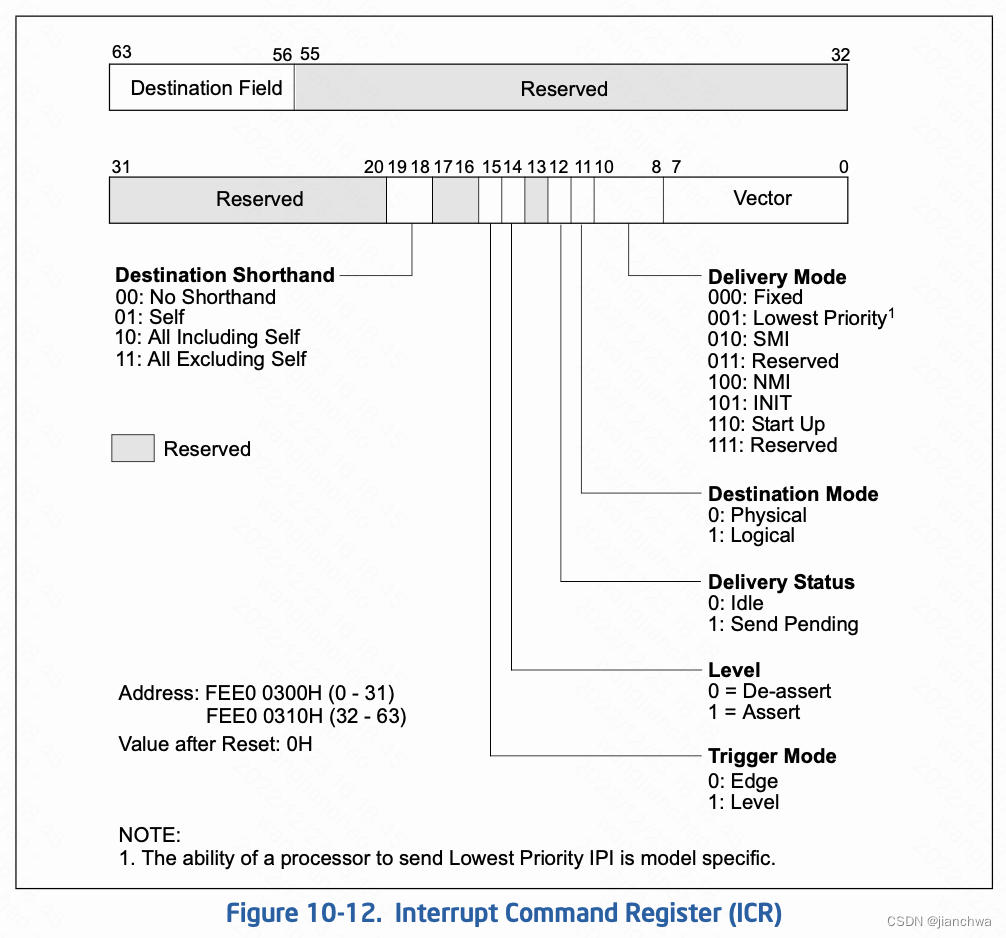
IPI的两个主要的使用场景是,resched和smp call function,参考代码:
resched_curr()
  -> smp_send_reschedule()
    -> native_smp_send_reschedule()
      -> apic->send_IPI(cpu, RESCHEDULE_VECTOR);


smp_call_function_many()
  -> arch_send_call_function_ipi_mask()
	 -> native_send_call_func_ipi()
	    ---
		if (cpumask_equal(mask, allbutself) &&
		    cpumask_equal(cpu_online_mask, cpu_callout_mask))
			apic->send_IPI_allbutself(CALL_FUNCTION_VECTOR);
		else
			apic->send_IPI_mask(mask, CALL_FUNCTION_VECTOR);
		---
__x2apic_send_IPI_mask()
---
	local_irq_save(flags);

	this_cpu = smp_processor_id();
	for_each_cpu(query_cpu, mask) {
		if (apic_dest == APIC_DEST_ALLBUT && this_cpu == query_cpu)
			continue;
		__x2apic_send_IPI_dest(per_cpu(x86_cpu_to_apicid, query_cpu),
				       vector, APIC_DEST_PHYSICAL);
		  -> native_x2apic_icr_write()
	        -> wrmsrl(APIC_BASE_MSR + (APIC_ICR >> 4), ((__u64) id) << 32 | low);
	}
	local_irq_restore(flags)
---
lapic在响应中断的过程中,有几个关键寄存器:
- IRR(Interrupt Request Register),256个bits,read-only
- ISR(In Service Register),246个bits, read-only
- EOI(End of Interrupt),32bits,write-only, For all interrupts except those delivered with the NMI, SMI, INIT, ExtINT, the start-up, or INIT-Deassert delivery mode, the interrupt handler must include a write to the end-of-interrupt (EOI) register . This write must occur at the end of the handler routine, sometime before the IRET instruction. This action indicates that the servicing of the current interrupt is complete and the local APIC can issue the next interrupt from the ISR;Upon receiving an EOI, the APIC clears the highest priority bit in the ISR and dispatches the next highest priority interrupt to the processor.
- TPR(Task Priority Register) ,read-write,寄存器的bits 7:4 用来定义 task-priority class;
- PPR(Processor Priority Register),read-only,寄存器的bits 7:4用来定义processor-priority class;The value of the PPR is based on the value of TPR and the value ISRV; ISRV is the vector number of the highest priority bit that is set in the ISR or 00H if no bit is set in the ISR;
- Vector Priority = vector number / 16
中断处理过程中,以上寄存器的工作过程如下:
- 中断首先进入IRR pending,然后选择其中优先级最高的一个vector;
- 如果该vector高于PPR,则进入ISR,并通知CPU进入中断处理;
- CPU处理完中断,将vector写入EOI,ISR中的相关vector被clear,同时,重新从IRR中选择一个新的vector;
3.3.2 APIC模拟
我们首先看下中断处理部分;
首先,模拟的lapic内部申请了一段内存,用来保存lapic的寄存器内容,
kvm_create_lapic()
---
	apic->regs = (void *)get_zeroed_page(GFP_KERNEL_ACCOUNT);
---

几个关键寄存器的访问方式大致如下:
kvm_lapic_set_vector(vec, apic->regs + APIC_IRR);


代码涉及apicv的部分,这里先略过,我们会在后面的章节详述

在向lapic发送中断时,首先设置了irr
kvm_apic_set_irq()
  -> __apic_accept_irq()
	 ---
	case APIC_DM_FIXED:
		...
		if (vcpu->arch.apicv_active)
			kvm_x86_ops->deliver_posted_interrupt(vcpu, vector);
		else {
			kvm_lapic_set_irr(vector, apic);

			kvm_make_request(KVM_REQ_EVENT, vcpu);
			kvm_vcpu_kick(vcpu);
		}
		break;
	 ---

在获取中断vector时,
kvm_cpu_get_interrupt()
  -> kvm_get_apic_interrupt()
    -> kvm_apic_has_interrupt()
	  -> __apic_update_ppr()
	     ---
			old_ppr = kvm_lapic_get_reg(apic, APIC_PROCPRI);
			tpr = kvm_lapic_get_reg(apic, APIC_TASKPRI);
			isr = apic_find_highest_isr(apic);
			isrv = (isr != -1) ? isr : 0;

			if ((tpr & 0xf0) >= (isrv & 0xf0))
				ppr = tpr & 0xff;
			else
				ppr = isrv & 0xf0;

			*new_ppr = ppr;
			if (old_ppr != ppr)
				kvm_lapic_set_reg(apic, APIC_PROCPRI, ppr);

         ppr的值来自tpr和isr
		 ---
      -> apic_has_interrupt_for_ppr()
	     ---
			if (apic->vcpu->arch.apicv_active)
				highest_irr = kvm_x86_ops->sync_pir_to_irr(apic->vcpu);
			else
				highest_irr = apic_find_highest_irr(apic);
			if (highest_irr == -1 || (highest_irr & 0xF0) <= ppr)
				return -1;
			return highest_irr;
         获得irr中高于ppr的那个vector
		 ---

kvm_get_apic_interrupt()
---
	int vector = kvm_apic_has_interrupt(vcpu);
	...
    根据获得vector设置isr
	apic_set_isr(vector, apic);
	__apic_update_ppr(apic, &ppr);

	return vector;
---

//清理isr,并处理下一个
kvm_lapic_reg_write()
  -> apic_set_eoi()
	 ---
	apic_clear_isr(vector, apic);
	apic_update_ppr(apic);

	kvm_ioapic_send_eoi(apic, vector);
	kvm_make_request(KVM_REQ_EVENT, apic->vcpu);
	 ---
上面只是一个模拟lapic内部寄存操作的部分,怎么给VM触发中断呢?
kvm_make_request(KVM_REQ_EVENT, vcpu);
kvm_vcpu_kick(vcpu);


首先需要让目标VCPU vm-exit,
kvm_vcpu_kick()
---
	me = get_cpu();
	if (cpu != me && (unsigned)cpu < nr_cpu_ids && cpu_online(cpu))

		if (kvm_arch_vcpu_should_kick(vcpu))
		    // return cmpxchg(&vcpu->mode, IN_GUEST_MODE, EXITING_GUEST_MODE) == IN_GUEST_MODE;
			smp_send_reschedule(cpu);
	        // RESCHEDULE_VECTOR
	put_cpu();
---
这里给目标CPU发送了一个IPI中断,vector为RESCHEDULE_VECTOR
参考Intel SDM 3 24.6.1 Pin-Based VM-Execution Controls

setup_vmcs_config()
---
	min = PIN_BASED_EXT_INTR_MASK | PIN_BASED_NMI_EXITING;
	opt = PIN_BASED_VIRTUAL_NMIS | PIN_BASED_POSTED_INTR |
		 PIN_BASED_VMX_PREEMPTION_TIMER;
	if (adjust_vmx_controls(min, opt, MSR_IA32_VMX_PINBASED_CTLS,
				&_pin_based_exec_control) < 0)
		return -EIO;
---

vcpu_enter_guest()
---
	kvm_before_interrupt(vcpu);
	kvm_x86_ops->handle_external_intr(vcpu);
	kvm_after_interrupt(vcpu);
---
vmx_handle_external_intr()
---
	u32 exit_intr_info = vmcs_read32(VM_EXIT_INTR_INFO);

	if ((exit_intr_info & (INTR_INFO_VALID_MASK | INTR_INFO_INTR_TYPE_MASK))
			== (INTR_INFO_VALID_MASK | INTR_TYPE_EXT_INTR)) {
		unsigned int vector;
		unsigned long entry;
		gate_desc *desc;
		struct vcpu_vmx *vmx = to_vmx(vcpu);
#ifdef CONFIG_X86_64
		unsigned long tmp;
#endif

		vector =  exit_intr_info & INTR_INFO_VECTOR_MASK;
		desc = (gate_desc *)vmx->host_idt_base + vector;
		entry = gate_offset(desc);
		asm volatile(
#ifdef CONFIG_X86_64
			"mov %%" _ASM_SP ", %[sp]\n\t"
			"and $0xfffffffffffffff0, %%" _ASM_SP "\n\t"
			"push $%c[ss]\n\t"
			"push %[sp]\n\t"
#endif
			"pushf\n\t"
			__ASM_SIZE(push) " $%c[cs]\n\t"
			CALL_NOSPEC
			:
#ifdef CONFIG_X86_64
			[sp]"=&r"(tmp),
#endif
			ASM_CALL_CONSTRAINT
			:
			THUNK_TARGET(entry),
			[ss]"i"(__KERNEL_DS),
			[cs]"i"(__KERNEL_CS)
			);
	}
}

---
在vmx_handle_external_interrtupt(),host端的IDT会被调用。
kvm_kick_vcpu()在触发vm-exit之后,vcpu_enter_guest()检查KVM_REQ_EVENT标记,并检查是否需要中断注入:
vcpu_enter_guest()
---
if (kvm_check_request(KVM_REQ_EVENT, vcpu) || req_int_win) {
++vcpu->stat.req_event;
kvm_apic_accept_events(vcpu);
...
if (inject_pending_event(vcpu, req_int_win) != 0) {
...
}
---
inject_pending_event()
---
if (kvm_cpu_has_injectable_intr(vcpu)) { // kvm_apic_has_interrupt() != -1
...
if (kvm_x86_ops->interrupt_allowed(vcpu)) {
//将从虚拟apic中获得的中断vector注入到vcpu中
kvm_queue_interrupt(vcpu, kvm_cpu_get_interrupt(vcpu),
false);
---
vcpu->arch.interrupt.injected = true;
vcpu->arch.interrupt.soft = soft;
vcpu->arch.interrupt.nr = vector;
---
kvm_x86_ops->set_irq(vcpu);
}
}
---
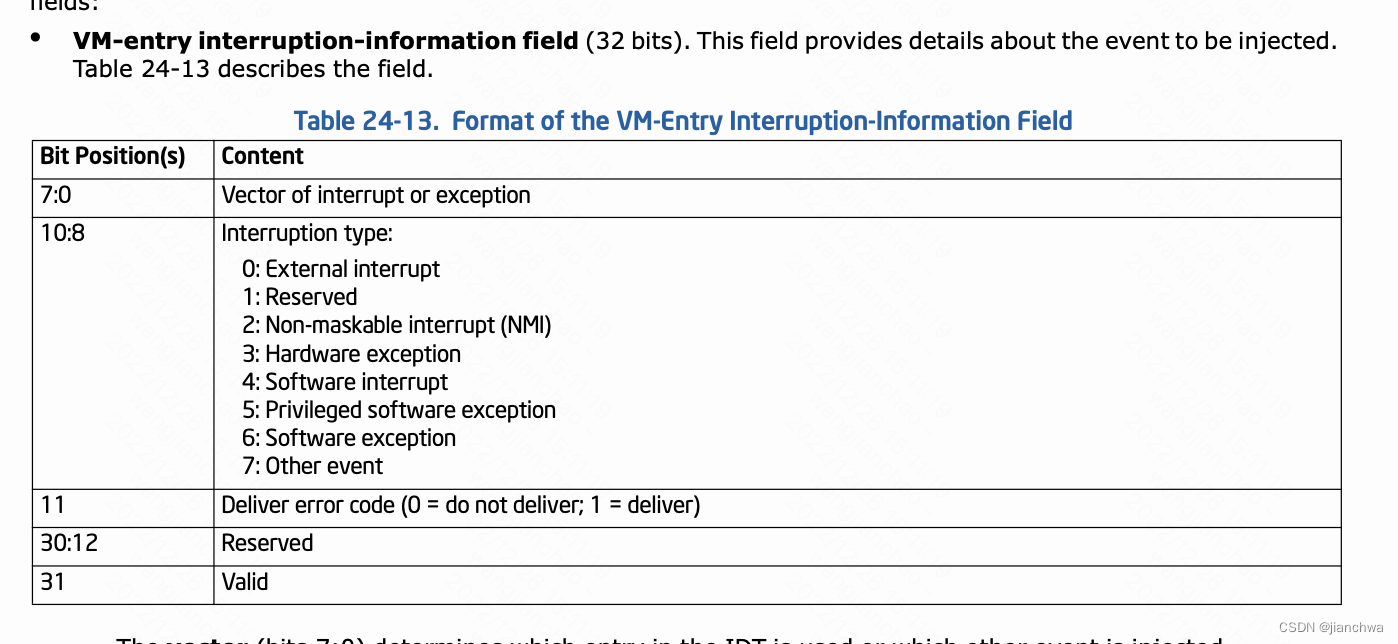
vmx_inject_irq()
---
int irq = vcpu->arch.interrupt.nr;
...
intr = irq | INTR_INFO_VALID_MASK;
if (vcpu->arch.interrupt.soft) {
intr |= INTR_TYPE_SOFT_INTR;
vmcs_write32(VM_ENTRY_INSTRUCTION_LEN,
vmx->vcpu.arch.event_exit_inst_len);
} else
intr |= INTR_TYPE_EXT_INTR;
vmcs_write32(VM_ENTRY_INTR_INFO_FIELD, intr);
---
向Guest VM诸如中断依赖的是vmx的机制,参考Intel SDM 3 24.8.3 VM-Entry Controls for Event Injection,
综上,对于纯软件的APIC模拟来说,要想给VCPU发一个中断,需要两个步骤:
- 用IPI触发VCPU vm-exit
- 向VCPU 注入一个中断
LAPIC模拟IPI的过程则更加曲折,因为这还涉及到MMIO或者MSR的写操作,参考代码:
kvm_x2apic_msr_write()
apic_mmio_write()
  -> kvm_lapic_reg_write()
	---
		kvm_lapic_set_reg(apic, APIC_ICR, val & ~(1 << 12));
		apic_send_ipi(apic);
	---

apic_send_ipi()
  -> kvm_irq_delivery_to_apic()
	-> kvm_irq_delivery_to_apic_fast()
	  -> kvm_apic_set_irq()
无论是msr还是mmio,都会触发一个vm-exit,然后,中断的处理过程大体跟外部中断一致;不过,不需要额外再触发一次vm-exit:
3.3.3 VAPIC
上一小节中描述的APIC的模拟过程,涉及到多个vm-exit,包括:
- APIC register的读写操作,这里影响最大的是EOI寄存机;
- Virtual interrupt delivery,需要首先通过IPI让Guest vm-exit,然后执行中断注入;
Intel给出了解决方案,即VAPIC,参考Intel SDM 3主要有以下几点:
Virtual-APIC page
The virtual-APIC page is a 4-KByte region of memory that the processor uses to virtualize certain accesses to APIC registers and to manage virtual interrupts. The physical address of the virtual-APIC page is the virtual-APIC address, a 64-bit VM-execution control field in the VMCS.
每个vcpu的vapic都有一个virtual apic page用来保存vapic的寄存器的状态,Guest OS对vapic寄存器的操作会在virtual apic page的基础上进行虚拟化;如此,可以避免对vapic寄存器操作引起的vm-exit;
这里我们看下x2apic的情况(xapic的MMIO的情况基本类似),
If “APIC-register virtualization” is 1 and ECX contains a value in the range 800H–8FFH, the instruction reads the 8 bytes from offset X on the virtual-APIC page into EDX:EAX, where X = (ECX & FFH) « 4.
对于WRMSR的操作,我们看下virtual interrupt delivery和EOI的虚拟化;
Virtual Interrupt Delivery流程:参考29.2.2 Virtual-InterruptDelivery
While true
IF any bits set in VIRR
THEN
RVI = highest index of bit set in VIRR
ELSE
RVI = 0;
FI;
IF RVI == 0
THEN
break
FI
Vector = RVI;
VIRR[Vector] = 0;
VISR[Vector] = 1;
SVI = Vector;
VPPR = Vector & F0H;deliver interrupt with Vector through IDT;
流程触发有以下时机:
- VM entry;
- TPR virtualization;
- EOI virtualization;
- self-IPI virtualizatio;
- posted-interrupt processing
EOI寄存器的虚拟化,参考Intel SDM 3 29.5 VIRTUALIZING MSR-BASED APIC ACCESSES,
WRMSR,
If ECX contains 80BH (indicating the EOI MSR) and the “virtual-interrupt delivery” VM-execution control is 1; WRMSR stores EDX:EAX at offset X on the virtual-APIC page, where X = (ECX & FFH) « 4.
Then the processor performs EOI virtualization (see Section 29.1.4). EOI virtualization uses and updates the guest interrupt status (specifically, SVI; see Section 24.4.2). The following pseudocode details the behavior of EOI virtualization:
Vector = SVI;
VISR[Vector] = 0;IF any bits set in VISR
THEN
SVI = highest index of bit set in VISR
ELSE
SVI = 0;
FI;
perform PPR virtualiation
IF EOI_exit_bitmap[Vector] = 1THEN
cause EOI-induced VM exit with Vector as exit qualification;
ELSE
evaluate pending virtual interrupts;
Posted-interrupt proccessing,这是一种虚拟中断发布机制,有两个关键的VMCS域:
- posted-interrupt notification vector
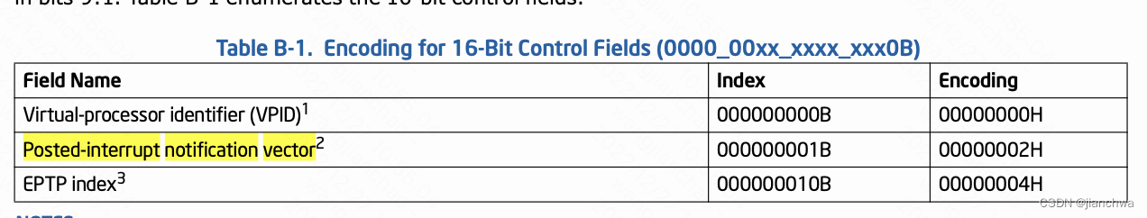
- Posted-interrupt Descirptor ,即PIR
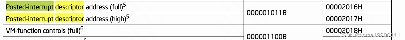
这两个域是这样配合工作的:
- vcpu给自己的vmcs设置一个合理的posted-interrupt notification vector,我们称之为V
- 当我们通过IPI机制,给该vcpu所在的物理cpu发送V vector时,会触发该CPU的posted-interrupt processing机制
- posted-interrupt processing机制被触发之后,硬件自动将PIR的值OR进vcpu的VIRR,然后进入virtual-interrrupt delivery机制
- PIR的值可以在vcpu运行在non-root operations时设置,但是需要使用cmpxchg指令
SDM中的原文是:
- The local APIC is acknowledged; this provides the processor core with an interrupt vector, called here the physical vector.
- If the physical vector equals the posted-interrupt notification vector, the logical processor continues to the next step. Otherwise, a VM exit occurs as it would normally due to an external interrupt; the vector is saved in the VM-exit interruption-information field.
- The processor clears the outstanding-notification bit in the posted-interrupt descriptor. This is done atomically so as to leave the remainder of the descriptor unmodified (e.g., with a locked AND operation).
- The processor writes zero to the EOI register in the local APIC; this dismisses the interrupt with the postedinterrupt notification vector from the local APIC.
- The logical processor performs a logical-OR of PIR into VIRR and clears PIR. No other agent can read or write a PIR bit (or group of bits) between the time it is read (to determine what to OR into VIRR) and when it is cleared.
- The logical processor sets RVI to be the maximum of the old value of RVI and the highest index of all bits that were set in PIR; if no bit was set in PIR, RVI is left unmodified.
- The logical processor evaluates pending virtual interrupts as described in Section 29.2.1
如此,我们就可以在不引起vm-exit的情况下,向vcpu注入中断。
参考代码:
#define POSTED_INTR_WAKEUP_VECTOR	0xf1

vmx_vcpu_setup()
---
	if (kvm_vcpu_apicv_active(&vmx->vcpu)) {
		vmcs_write64(EOI_EXIT_BITMAP0, 0);
		vmcs_write64(EOI_EXIT_BITMAP1, 0);
		vmcs_write64(EOI_EXIT_BITMAP2, 0);
		vmcs_write64(EOI_EXIT_BITMAP3, 0);

		vmcs_write16(GUEST_INTR_STATUS, 0);

		// Posted-interrrupt notification vector
		vmcs_write16(POSTED_INTR_NV, POSTED_INTR_VECTOR);
		// PIR .....
		vmcs_write64(POSTED_INTR_DESC_ADDR, __pa((&vmx->pi_desc)));
	}
---

__apic_accept_irq()
---
		if (vcpu->arch.apicv_active)
			kvm_x86_ops->deliver_posted_interrupt(vcpu, vector);
		else {
			kvm_lapic_set_irr(vector, apic);

			kvm_make_request(KVM_REQ_EVENT, vcpu);
			kvm_vcpu_kick(vcpu);
		}
---

vmx_deliver_posted_interrupt()
---
	// Update PIR
	if (pi_test_and_set_pir(vector, &vmx->pi_desc))
		return;

	/* If a previous notification has sent the IPI, nothing to do.  */
	if (pi_test_and_set_on(&vmx->pi_desc))
		return;

	if (!kvm_vcpu_trigger_posted_interrupt(vcpu, false))
		kvm_vcpu_kick(vcpu);
---

kvm_vcpu_trigger_posted_interrupt()
---
#ifdef CONFIG_SMP
	int pi_vec = nested ? POSTED_INTR_NESTED_VECTOR : POSTED_INTR_VECTOR;

	if (vcpu->mode == IN_GUEST_MODE) {
		apic->send_IPI_mask(get_cpu_mask(vcpu->cpu), pi_vec);
		return true;
	}
#endif
	return false;
---
注意之前对PI的Delivery的过程的描述:
If the physical vector equals the posted-interrupt notification vector, the logical processor continues to the next step. Otherwise, a VM exit occurs as it would normally due to an external interrupt; the vector is saved in the VM-exit interruption-information field.
如果此时,该CPU已经退出了non-root模式,换句话说,没有loaded VMCS,也就没有posted-interrupt notification vector,这种情况,要怎么处理?
首先,如果POST_INTERRUPT_VECTOR被发送到没有VMCS的CPU上,
/*
 * Handler for POSTED_INTERRUPT_VECTOR.
 */
DEFINE_IDTENTRY_SYSVEC_SIMPLE(sysvec_kvm_posted_intr_ipi)
{
	ack_APIC_irq();
	inc_irq_stat(kvm_posted_intr_ipis);
}
这个vector会被以上方式处理;对于被Post给相关VCPU的Vector,可以参考函数:
static inline void kvm_vcpu_trigger_posted_interrupt(struct kvm_vcpu *vcpu,
						     int pi_vec)
{
#ifdef CONFIG_SMP
	if (vcpu->mode == IN_GUEST_MODE) {
		/*
		 * The vector of the virtual has already been set in the PIR.
		 * Send a notification event to deliver the virtual interrupt
		 * unless the vCPU is the currently running vCPU, i.e. the
		 * event is being sent from a fastpath VM-Exit handler, in
		 * which case the PIR will be synced to the vIRR before
		 * re-entering the guest.
		 *
		 * When the target is not the running vCPU, the following
		 * possibilities emerge:
		 *
		 * Case 1: vCPU stays in non-root mode. Sending a notification
		 * event posts the interrupt to the vCPU.
		 *
		 * Case 2: vCPU exits to root mode and is still runnable. The
		 * PIR will be synced to the vIRR before re-entering the guest.
		 * Sending a notification event is ok as the host IRQ handler
		 * will ignore the spurious event.
		 *
		 * Case 3: vCPU exits to root mode and is blocked. vcpu_block()
		 * has already synced PIR to vIRR and never blocks the vCPU if
		 * the vIRR is not empty. Therefore, a blocked vCPU here does
		 * not wait for any requested interrupts in PIR, and sending a
		 * notification event also results in a benign, spurious event.
		 */

		if (vcpu != kvm_get_running_vcpu())
			apic->send_IPI_mask(get_cpu_mask(vcpu->cpu), pi_vec);
		return;
	}
#endif
	/*
	 * The vCPU isn't in the guest; wake the vCPU in case it is blocking,
	 * otherwise do nothing as KVM will grab the highest priority pending
	 * IRQ via ->sync_pir_to_irr() in vcpu_enter_guest().
	 */
	kvm_vcpu_wake_up(vcpu);
}
当vcpu不在non-root模式时,它可能在用户态QEMU或者其他内核路径,或者在vcpu_block(),对对于这些情况,在vcpu再次进入non-root模式之前,会执行sync PIR to vIRR,参考代码:
vcpu_enter_guest()
---
	/*
	 * Process pending posted interrupts to handle the case where the
	 * notification IRQ arrived in the host, or was never sent (because the
	 * target vCPU wasn't running).  Do this regardless of the vCPU's APICv
	 * status, KVM doesn't update assigned devices when APICv is inhibited,
	 * i.e. they can post interrupts even if APICv is temporarily disabled.
	 */
	if (kvm_lapic_enabled(vcpu))
		static_call_cond(kvm_x86_sync_pir_to_irr)(vcpu);
	...
	for (;;) {
		...
		exit_fastpath = static_call(kvm_x86_vcpu_run)(vcpu);
		if (likely(exit_fastpath != EXIT_FASTPATH_REENTER_GUEST))
			break;

		if (kvm_lapic_enabled(vcpu))
			static_call_cond(kvm_x86_sync_pir_to_irr)(vcpu);
		...
	}
	...
---

vmx_sync_pir_to_irr()
---
if (pi_test_on(&vmx->pi_desc)) {
		pi_clear_on(&vmx->pi_desc);
		/*
		 * IOMMU can write to PID.ON, so the barrier matters even on UP.
		 * But on x86 this is just a compiler barrier anyway.
		 */
		smp_mb__after_atomic();
		got_posted_interrupt =
			kvm_apic_update_irr(vcpu, vmx->pi_desc.pir, &max_irr);
	} else {
		max_irr = kvm_lapic_find_highest_irr(vcpu);
		got_posted_interrupt = false;
	}
	...
	if (!is_guest_mode(vcpu) && kvm_vcpu_apicv_active(vcpu))
		vmx_set_rvi(max_irr);
	else if (got_posted_interrupt)
		kvm_make_request(KVM_REQ_EVENT, vcpu);

---
4 时钟虚拟化
4.1 时钟子系统
另外,链接
Timekeeping Virtualization for X86-Based Architectures — The Linux Kernel documentation![]() https://docs.kernel.org/virt/kvm/x86/timekeeping.html 中,介绍了集中常见的时钟常用的硬件;
https://docs.kernel.org/virt/kvm/x86/timekeeping.html 中,介绍了集中常见的时钟常用的硬件;
x86平台上,最常用的clocksource是tsc,引用链接TSC - OSDev Wikihttps://wiki.osdev.org/TSC
The Timestamp Counter is a 64-bit internal register which is present in all Intel processors after the Pentium. It stores the number of cycles executed by the CPU after the latest reset. The time-stamp counter can be read by software using the RDTSC instruction. It was a precise method of getting a high-resolution measure of the passage of time. But on hyper-threading and multi-core systems, user-level software cannot rely on it as the time-stamp counters of all the CPUs in the system may or may not be synchronized. Other than that, the speed of the CPU may change as the OS or BIOS may take power-saving steps or step-up the performance of the CPU using hardware-based mechanisms. But recent processors also allow a constant-rate TSC which ticks at the nominal frequency of the CPU rather than the current-frequency of the CPU which depends on a turbo state or power-saving state. This feature is used in kernels to record time with high-precision and low-overhead on each CPU.
4.1.1 Clocksource
The purpose of the clock source is to provide a timeline for the system that tells you where you are in time. Typically the clock source is a monotonic, atomic counter which will provide n bits which count from 0 to (2^n)-1 and then wraps around to 0 and start over.
可以通过以下方式获取系统中注册的clocksource和当前正在使用的:
cat /sys/devices/system/clocksource/clocksource0/available_clocksource
tsc hpet acpi_pm

cat /sys/devices/system/clocksource/clocksource0/current_clocksource
tsc
clocksource的注册通过clocksource_register_hz或者clocksource_register_khz,参考tsc和hpet的定义:
static struct clocksource clocksource_hpet = {
	.name		= "hpet",
	.rating		= 250,
	.read		= read_hpet,
	.mask		= HPET_MASK,   //CLOCKSOURCE_MASK(32)
	.flags		= CLOCK_SOURCE_IS_CONTINUOUS,
	.resume		= hpet_resume_counter,
};

static struct clocksource clocksource_tsc = {
	.name                   = "tsc",
	.rating                 = 300,
	.read                   = read_tsc,
	.mask                   = CLOCKSOURCE_MASK(64),
	.flags                  = CLOCK_SOURCE_IS_CONTINUOUS |
				  CLOCK_SOURCE_VALID_FOR_HRES |
				  CLOCK_SOURCE_MUST_VERIFY,
	.archdata               = { .vclock_mode = VCLOCK_TSC },
	.resume			= tsc_resume,
	.mark_unstable		= tsc_cs_mark_unstable,
	.tick_stable		= tsc_cs_tick_stable,
	.list			= LIST_HEAD_INIT(clocksource_tsc.list),
};
关注其中有几个关键的域:
- rating,这是一个分数,参考其定义的注释:
1-99: Unfit for real use Only available for bootup and testing purposes. 100-199: Base level usability. Functional for real use, but not desired. 200-299: Good. A correct and usable clocksource. 300-399: Desired. A reasonably fast and accurate clocksource. 400-499: Perfect The ideal clocksource. A must-use where available. - mask,counter的位数,用来计算clocksource的超时时间
- read,用于读取counter的值,
ktime_get()
  -> timekeeping_get_ns()
	-> timekeeping_get_delta()
	   ---
		do {
			seq = read_seqcount_begin(&tk_core.seq);
			now = tk_clock_read(tkr);
			last = tkr->cycle_last;
			mask = tkr->mask;
			max = tkr->clock->max_cycles;
		} while (read_seqcount_retry(&tk_core.seq, seq));

		delta = clocksource_delta(now, last, mask);
	   ---
最佳的clocksource就是rating值最高的,它通过以下代码路径通知给timekeeping子系统,
__clocksource_register_scale()
  -> __clocksource_select()
	-> timekeeping_notify()
	  -> stop_machine(change_clocksource, clock, NULL);
	    -> tk_setup_internals()
4.1.2 Clockevent
Clock events are orthogonal to clock sources. The same hardware and register range may be used for the clock event, but it is essentially a different thing. The hardware driving clock events has to be able to fire interrupts, so as to trigger events on the system timeline.
Clockevent与Clocksource可能来自同一个硬件;clockevent的最大用处是为定时器提供底层支持,就像是一个闹钟;参考下图,clockevent和其他功能模块的关系;
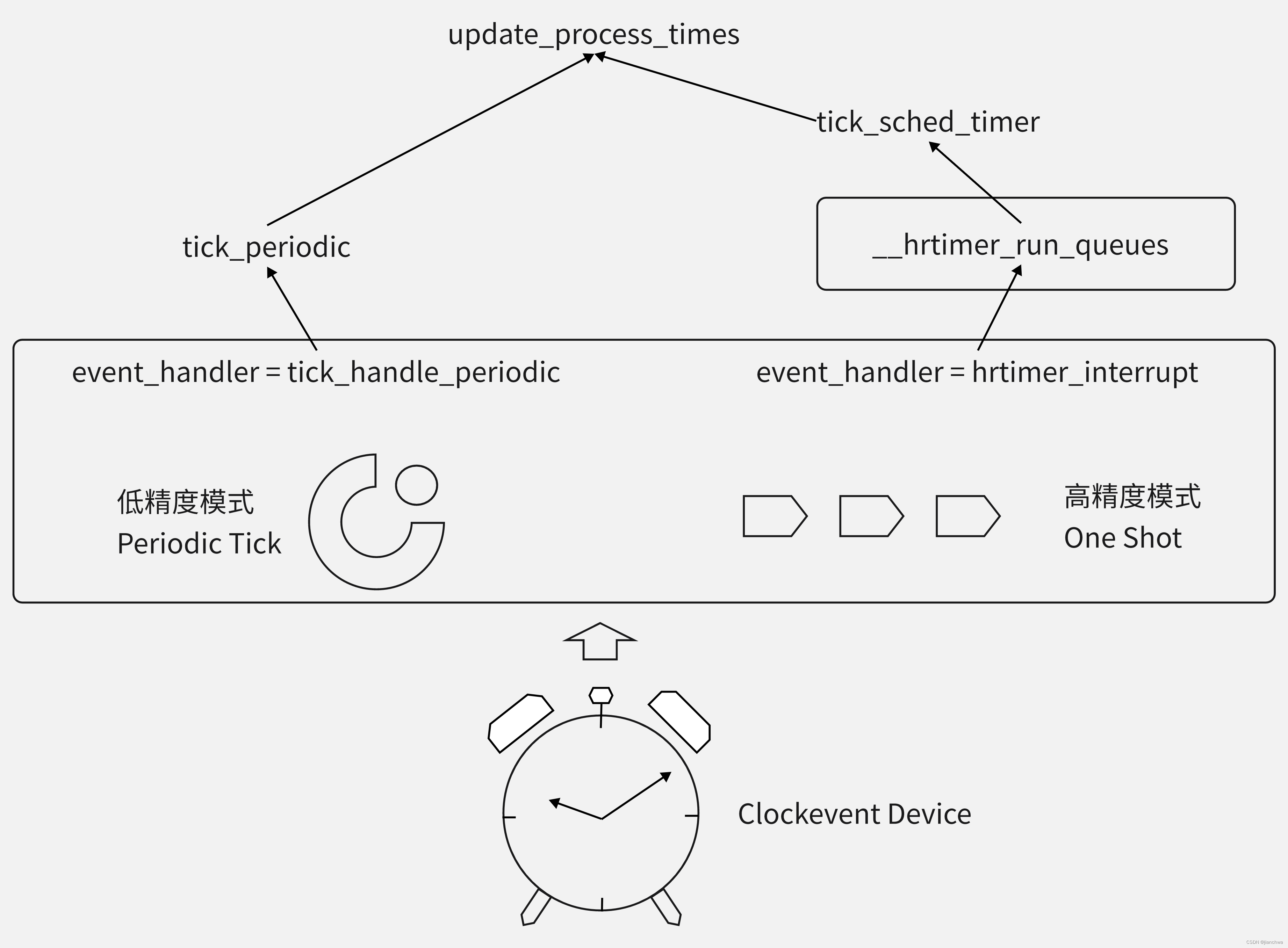
需要说明的是,系统在刚启动的时候,是运行在低精度模式的;之后,会检测是否可以转换到高精度模式,参考代码:
clockevents_register_device()
  -> tick_check_new_device()
    -> tick_setup_device()
	  -> tick_setup_device()
	    -> tick_setup_periodic()

tick_handle_periodic()
  -> tick_periodic()
	-> update_process_times()
	  -> run_local_timers()
	    -> hrtimer_run_queues()
	      -> hrtimer_switch_to_hres()
	        -> tick_init_highres()
4.1.3 sched_clock
关于sched_lock有以下几个关键点:
- sched_clock()返回的自系统启动依赖的纳秒数;
- sched_clock()主要用于调度子系统,调用频繁比较高,所以它必须实现的比较轻且快;
- 如果架构没有实现,sched_clock()会退化到使用jiffies
在x86架构上,sched_clock()使用的是rdtsc,参考代码:
/*
 * Scheduler clock - returns current time in nanosec units.
 */
u64 native_sched_clock(void)
{
	if (static_branch_likely(&__use_tsc)) {
		u64 tsc_now = rdtsc();

		/* return the value in ns */
		return cycles_2_ns(tsc_now);
	}

	/*
	 * Fall back to jiffies if there's no TSC available:
	 * ( But note that we still use it if the TSC is marked
	 *   unstable. We do this because unlike Time Of Day,
	 *   the scheduler clock tolerates small errors and it's
	 *   very important for it to be as fast as the platform
	 *   can achieve it. )
	 */

	/* No locking but a rare wrong value is not a big deal: */
	return (jiffies_64 - INITIAL_JIFFIES) * (1000000000 / HZ);
}
4.2 虚拟化
时钟虚拟化过程中,clocksource和clockevent都会变的不准确:
- 因为Guest VM的中断并不是真正的中断,而是由Host注入的,所以,它可能并不及时;
- Guest vcpu是以一个task的方式运行,它并不会独占一个cpu,可能被别的vcpu或者系统任务抢占,这一方面会导致Guest OS响应时钟中断不及时,也会导致clocksource获取的时间不准确;举个例子,在过去的1s内,可能这个Guest vcpu只运行了100ms;
我们看下kvm会如何解决这些问题。
4.2.1 clocksource
首先,我们考虑以下场景:
                  GT0       GT1
Guest :  |--------.        .-------->
                  |        |
Host  :           '--------'
                  HT0         HT1


Guest的vcpu实际上是一个进程,它有可能被Host上的其他任务抢占,
假设这段时间是(HT1 - HT0)
当Guest的vcpu又得到调度时,GT1的值该是多少呢?

GT1是等于GT0还是GT0 + (HT1 - HT0) ?直觉上,我们觉得GT1应该等于GT0;但是这里我们要考虑的是,虚拟机中的 Wall Time必须和外面的时间一致。
Intel VMX支持rdtsc指令vm-exit,参考:
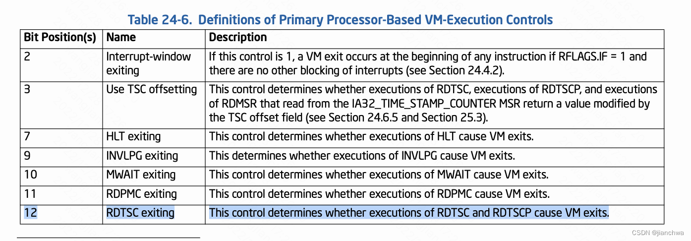
但是,内核没有用这个功能,也就是说Guest OS调用rdtsc并不会vm-exit;
如果作为Guest OS,linux kernel使用的是半虚拟化的kvm-clock。

kvm-clock要解决哪些问题?链接
Comparing with physical problems, the virtualization introduced more challenges regarding to TSC sync. For example, VM live migration may cause TSC sync problems if source and target hosts are different from hardware and software levels,
- Platform type differences (Intel vs AMD, reliable vs unreliable)
- CPU frequency (TSC increase rate)
- CPU boot time (TSC initial values)
- Hypervisor version differences
So the behaviors of TSC sync on different hypervisors could cause the TSC sync problems.
同时,kvmclock的提交commit中,也提到其实现原理,可以参考
[PATCH 5/5] add documentation about kvmclock![]() https://lkml.org/lkml/2010/4/15/355kvm-clock要解决的是TSC sync的问题,尤其是Guest Live Migration的时候,它可能被迁移到别的机器上,前后的CPU frequency(TSC increase rate)和CPU boot time(TSC initial values)不同;kvmclock的解决方法是:
https://lkml.org/lkml/2010/4/15/355kvm-clock要解决的是TSC sync的问题,尤其是Guest Live Migration的时候,它可能被迁移到别的机器上,前后的CPU frequency(TSC increase rate)和CPU boot time(TSC initial values)不同;kvmclock的解决方法是:
struct clocksource kvm_clock = {
	.name	= "kvm-clock",
	.read	= kvm_clock_get_cycles,
	.rating	= 400,
	.mask	= CLOCKSOURCE_MASK(64),
	.flags	= CLOCK_SOURCE_IS_CONTINUOUS,
};

kvm_clock_get_cycles()
  -> kvm_clock_read()
    -> pvclock_clocksource_read()
	  -> __pvclock_read_cycles(src, rdtsc_ordered())

u64 __pvclock_read_cycles(const struct pvclock_vcpu_time_info *src, u64 tsc)
---
	u64 delta = tsc - src->tsc_timestamp;
	u64 offset = pvclock_scale_delta(delta, src->tsc_to_system_mul,
					     src->tsc_shift);
	return src->system_time + offset;
---
kvmclock的计算公式大致为:
delta = rdtsc_ordered() - tsc_timestamp
kvmclock = system_time + fn(delta, tsc_to_system_mul, tsc_shift)
其中:
- tsc_timestamp和system_time由Host更新,分别是当时的ktime_get_boot_ns()和tsc值,Host端会在一定的时机更新,这个可以解决CPU boot time(TSC initial value)问题的
- tsc_to_system_mul和tsc_shift是解决CPU frequency(TSC increase rate)
Guest和Host共享数据的方式是:前者通过MSR寄存器将地址通知Host,参考代码:
kvm_register_clock()
---
	struct pvclock_vsyscall_time_info *src = this_cpu_hvclock();
	u64 pa;

	pa = slow_virt_to_phys(&src->pvti) | 0x01ULL;
	wrmsrl(msr_kvm_system_time, pa);
---


kvm_set_msr_common()
---
	case MSR_KVM_SYSTEM_TIME: {
		struct kvm_arch *ka = &vcpu->kvm->arch;

		kvmclock_reset(vcpu);

		if (kvm_gfn_to_hva_cache_init(vcpu->kvm,
		     &vcpu->arch.pv_time, data & ~1ULL,
		     sizeof(struct pvclock_vcpu_time_info)))
			vcpu->arch.pv_time_enabled = false;
		else
			vcpu->arch.pv_time_enabled = true;

注意,此MSR是每CPU的
kvmclock Host端的更新参考如下代码:
#define KVMCLOCK_SYNC_PERIOD (300 * HZ)
kvmclock_sync_fn()
---
	schedule_delayed_work(&kvm->arch.kvmclock_update_work, 0);
	schedule_delayed_work(&kvm->arch.kvmclock_sync_work,
					KVMCLOCK_SYNC_PERIOD);
---

kvmclock_update_fn()
---
	kvm_for_each_vcpu(i, vcpu, kvm) {
		kvm_make_request(KVM_REQ_CLOCK_UPDATE, vcpu);
		kvm_vcpu_kick(vcpu);
	}
---

vcpu_enter_guest()
---
	if (kvm_check_request(KVM_REQ_CLOCK_UPDATE, vcpu)) {
			r = kvm_guest_time_update(vcpu);
		}
---

可以看到,这个也是一个kvmclock sync的过程
4.2.2 Steal Time
我们依然引用上一小节中的例子:
             G-redis        G-redis
Guest :  |--------.        .-------->
                  |        |
Host  :           '--------'
                      H-redis
                  t0        t1

Guest的vcpu实际上是一个进程,它有可能被Host上的其他任务抢占,
t0时刻Host redis任务抢占vcpu线程,t1时刻vcpu被调度回来,
那么,t0 - t1这段时间,是否要算入Guest redis的运行时间里?
如果把t0 - t1算入Guest GA任务的运行时间的话,对GA毫无疑问是不公平的;
kvm引入的解决方案是:Steal Time
我们首先看下Steal Time是如何在Guest OS调度中发挥作用的,参考代码:
update_rq_clock()
---
delta = sched_clock_cpu(cpu_of(rq)) - rq->clock;
if (delta < 0)
return;
rq->clock += delta;
update_rq_clock_task(rq, delta);
---
update_rq_clock_task()
---
#ifdef CONFIG_PARAVIRT_TIME_ACCOUNTING
if (static_key_false((¶virt_steal_rq_enabled))) {
steal = paravirt_steal_clock(cpu_of(rq));
steal -= rq->prev_steal_time_rq;
if (unlikely(steal > delta))
steal = delta;
rq->prev_steal_time_rq += steal;
delta -= steal;
}
#endif
rq->clock_task += delta;
---
update_curr()
---
struct sched_entity *curr = cfs_rq->curr;
u64 now = rq_clock_task(rq_of(cfs_rq));
delta_exec = now - curr->exec_start;
curr->exec_start = now;
curr->sum_exec_runtime += delta_exec;
curr->vruntime += calc_delta_fair(delta_exec, curr);
...
---
steal time影响的是Guest OS的rq->task_clock,而cfs的任务的执行时间统计是依据task_clock的。
那么,steal time在Host上是如何统计的?参考代码:
__schedule()
  -> context_switch()
	-> prepare_task_switch()
	  -> fire_sched_out_preempt_notifiers()
	-> switch_to()
    -> finish_task_switch()
	  -> fire_sched_in_preempt_notifiers(current);

kvm_preempt_ops.sched_in kvm_sched_in()
	-> kvm_arch_vcpu_load()
	  -> kvm_make_request(KVM_REQ_STEAL_UPDATE, vcpu);

vcpu_enter_guest()
  -> record_steal_time()
	 ---
	vcpu->arch.st.steal.steal += current->sched_info.run_delay -
		vcpu->arch.st.last_steal;
	vcpu->arch.st.last_steal = current->sched_info.run_delay;

	kvm_write_guest_cached(vcpu->kvm, &vcpu->arch.st.stime,
		&vcpu->arch.st.steal, sizeof(struct kvm_steal_time));
	 ---

run_delay is schedule latency

prepare_task_switch()
  -> sched_info_switch()
	-> __sched_info_switch()
	  -> sched_info_arrive()
	     ---
		if (t->sched_info.last_queued)
			delta = rq_clock(rq) - t->sched_info.last_queued;
		t->sched_info.run_delay += delta;

enqueue_task()
  -> sched_info_queued()
	 ---
	if (unlikely(sched_info_on())) {
		if (!t->sched_info.last_queued)
			t->sched_info.last_queued = rq_clock(rq);
	}
	 ---
有以下几点需要说明:
- 这里的preempt notifier是per task的,kvm给vcpu的线程注册了这个
- run_delay是vcpu线程的调度延迟,即处于就绪态的时间(on_rq but not current)
PLUS,Guest和Host之间交换stealtime的方式,跟kvmclock类似,引入了一个MSR,MSR_KVM_STEAL_TIME。
4.2.3 clockevent
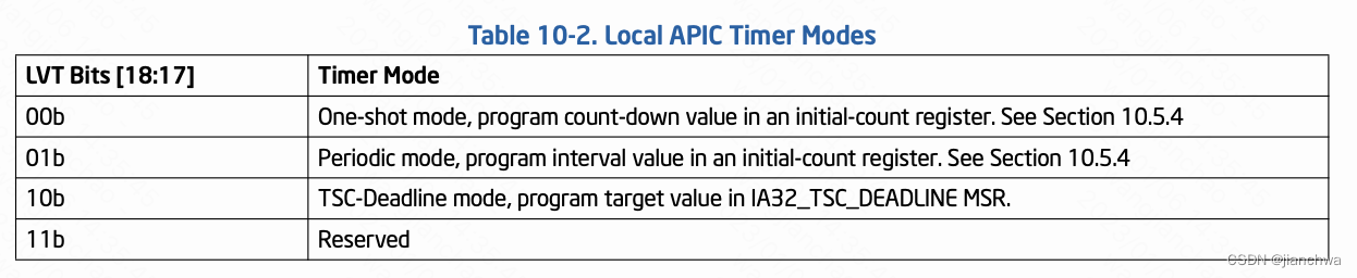
当前,Intel平台使用Local APIC Timer的TSC-deadline模式,作为clockevent,参考Intel SDM 3 10.5.4.1 TSC-Deadline Mode,
A write to the LVT Timer Register that changes the timer mode disarms the local APIC timer. The supported timer modes are given in Table 10-2. The three modes of the local APIC timer are mutually exclusive.
- TSC-deadline mode allows software to use the local APIC timer to signal an interrupt at an absolute time. In TSC- deadline mode, writes to the initial-count register are ignored; and current-count register always reads 0. Instead, timer behavior is controlled using the IA32_TSC_DEADLINE MSR.
- The IA32_TSC_DEADLINE MSR (MSR address 6E0H) is a per-logical processor MSR that specifies the time at which a timer interrupt should occur. Writing a non-zero 64-bit value into IA32_TSC_DEADLINE arms the timer.
- An interrupt is generated when the logical processor’s time-stamp counter equals or exceeds the target value in the IA32_TSC_DEADLINEMSR. When the timer generates an interrupt, it disarms itself and clears the IA32_TSC_DEADLINE MSR. Thus, each write to the IA32_TSC_DEADLINE MSR generates at most one timer interrupt.
- In TSC-deadline mode, writing 0 to the IA32_TSC_DEADLINE MSR disarms the local-APIC timer.
KVM要模拟TSC-deadline模式,需要做以下事情:
- 拦截并模拟Guest OS对TSC_DEADLINE MSR的操作,通过Host的hrtimer模拟APIC Timer
handle_wrmsr() -> kvm_set_msr() -> kvm_x86_ops->set_msr() -> kvm_set_msr_common() -> kvm_set_lapic_tscdeadline_msr() //MSR_IA32_TSCDEADLINE -> start_apic_timer(apic); -> start_sw_tscdeadline() --- now = ktime_get(); guest_tsc = kvm_read_l1_tsc(vcpu, rdtsc()); ns = (tscdeadline - guest_tsc) * 1000000ULL; do_div(ns, this_tsc_khz); if (likely(tscdeadline > guest_tsc) && likely(ns > apic->lapic_timer.timer_advance_ns)) { expire = ktime_add_ns(now, ns); expire = ktime_sub_ns(expire, ktimer->timer_advance_ns); hrtimer_start(&ktimer->timer, expire, HRTIMER_MODE_ABS_PINNED); } --- - 定时器超时之后,给Guest OS注入中断,
apic_timer_fn()
  -> apic_timer_expired()
    -> atomic_inc(&apic->lapic_timer.pending);

vcpu_run()
  -> apic_has_pending_timer()
	-> atomic_read(&apic->lapic_timer.pending)
  -> kvm_inject_pending_timer_irqs()
	-> kvm_inject_apic_timer_irqs()
	  -> kvm_apic_local_deliver(apic, APIC_LVTT)
	    -> __apic_accept_irq()

由于Timer中断的注入是在vcpu_run()中,所以其依赖Guest VM-exit,为了保证hrtimer在vcpu所在的
cpu上产生中断,

kvm_sched_in()
  -> kvm_arch_vcpu_load()
     ---
		if (vcpu->cpu != cpu)
			kvm_make_request(KVM_REQ_MIGRATE_TIMER, vcpu);
		vcpu->cpu = cpu;
	 ---

vcpu_enter_guest()
  -> __kvm_migrate_timers()
	-> __kvm_migrate_apic_timer()
	  ---
		timer = &vcpu->arch.apic->lapic_timer.timer;
		if (hrtimer_cancel(timer))
			hrtimer_start_expires(timer, HRTIMER_MODE_ABS_PINNED);
	  ---
> > Hi,
> >
> > I'm just wondering what's the reason why we use the preemption timer
> > instead of emulating VM's timer using hrtimer in software? Is there
> > anything the the preemption timer can do that can't be done with
> > hrtimer?
> >
> > I guess the x86 architecture provides the preemption timer for *some*
> > reason, but I'm not sure what they are.
>
> Assuming you're referring to Intel/VMX's preemption timer, programming
> the preemption timer and servicing its VM-Exits both have lower overhead
> than going through hrtimer.
参考Intel SDM 3 ,与vmx-preempt timer有关的域有以下,
24.4.2 Guest Non-Register State,VMX-preemption timer value (32 bits). This field is supported only on processors that support the 1-setting of the “activate VMX-preemption timer” VM-execution control. This field contains the value that the VMX- preemption timer will use following the next VM entry with that setting
25.5.1 VMX-Preemption Timer,If the last VM entry was performed with the 1-setting of “activate VMX-preemption timer” VM-execution control, the VMX-preemption timer counts down (from the value loaded by VM entry; see Section 26.6.4) in VMX non- root operation. When the timer counts down to zero, it stops counting down and a VM exit occurs
与之前的hrtimer相比,使用vmx-preempt timer有如下优势:
- 在setup timer时,不需要设置Host的APIC Timer,而只需要设置VMCS的vmx-preemption timer value域
- 在处理timeout时,不需要先处理hrtimer的host端的中断,而只需要处理相关的vm-exit
注:vmx-preempt timer的设置,依然需要依赖拦截TSC_DEADLINE MSR
看下代码:
EXIT_REASON_MSR_READ/EXIT_REASON_MSR_WRITE
handle_wrmsr()
  -> kvm_set_msr()
	-> kvm_x86_ops->set_msr()
	  -> kvm_set_msr_common()
	    -> kvm_set_lapic_tscdeadline_msr() //MSR_IA32_TSCDEADLINE
		  -> start_apic_timer(apic);
		    -> start_hv_timer()
	          -> kvm_x86_ops->set_hv_timer()
	             vmx_set_hv_timer()
	               -> vmx->hv_deadline_tsc = tscl + delta_tsc;

vmx_vcpu_run()
  -> vmx_update_hv_timer()
	-> vmx_arm_hv_timer()
	   ---
		vmcs_write32(VMX_PREEMPTION_TIMER_VALUE, val);
	   ---

EXIT_REASON_PREEMPTION_TIMER
handle_preemption_timer()
  -> kvm_lapic_expired_hv_timer()
	-> apic_timer_expired()


 1442
1442


 被折叠的 条评论
为什么被折叠?
被折叠的 条评论
为什么被折叠?
 到【灌水乐园】发言


