


硬件环境:Xilinx ZynqMP XCZU15eg-ffvb1156-2-i
软件环境:Vivado2018.3
目录
硬件环境:Xilinx ZynqMP XCZU15eg-ffvb1156-2-i
五:导出硬件平台信息,然后在SDK里新建一个helloworld工程;
六:将板子的A1和B1 以及A2,B2分别与外部串口通信工具连接,也即用485转USB连接电脑。
九:下一篇讲述使用UART16550的中断模式接收多种帧长的报文数据,也即接收不定长数据。
一:新建工程
打开Vivado,建立一个工程,选择芯片xczu15eg-ffvb-2-i,建立完毕后建立blockDesign,添加芯片进去。
二:芯片配置
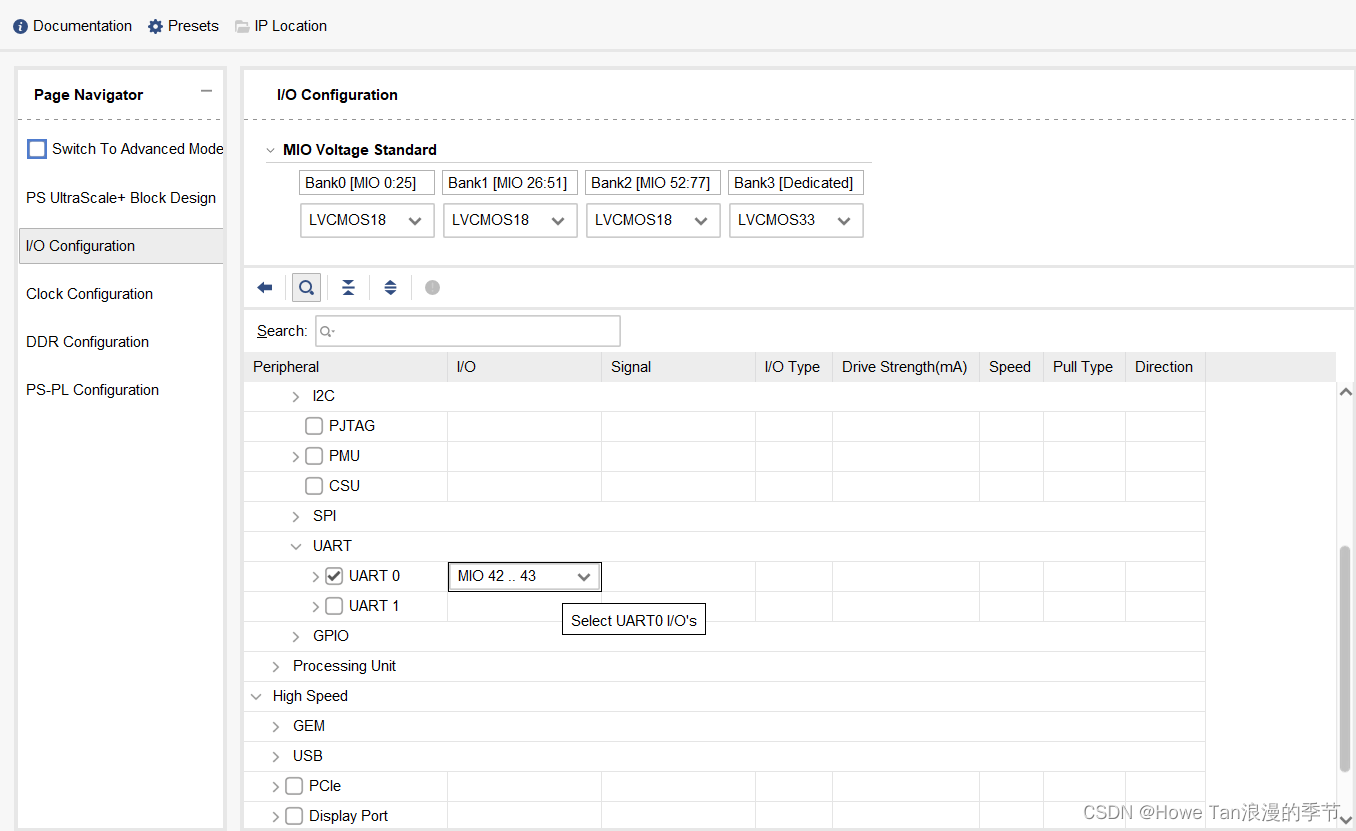
- 首先配置bank电压,分别为LVCMOS18,LVCMOS18,LVCMOS18,LVCMOS33
- 配置低速IO,包括QSPI,SD,UART等
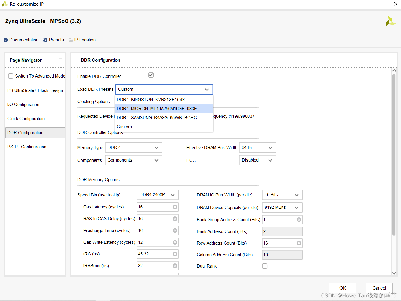
- 配置DDR
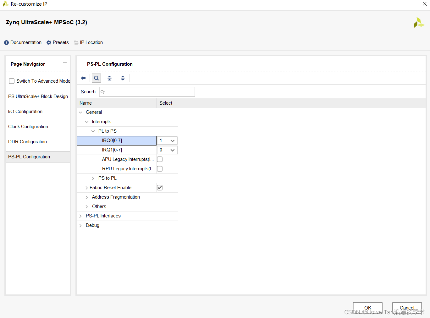
- 打开PLtoPS的中断;具体配置如下图所示:

三:添加IP核
先来一张总的设计图:
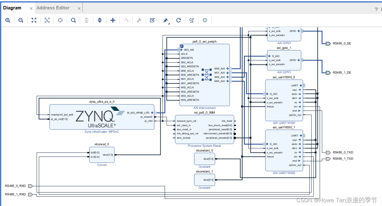
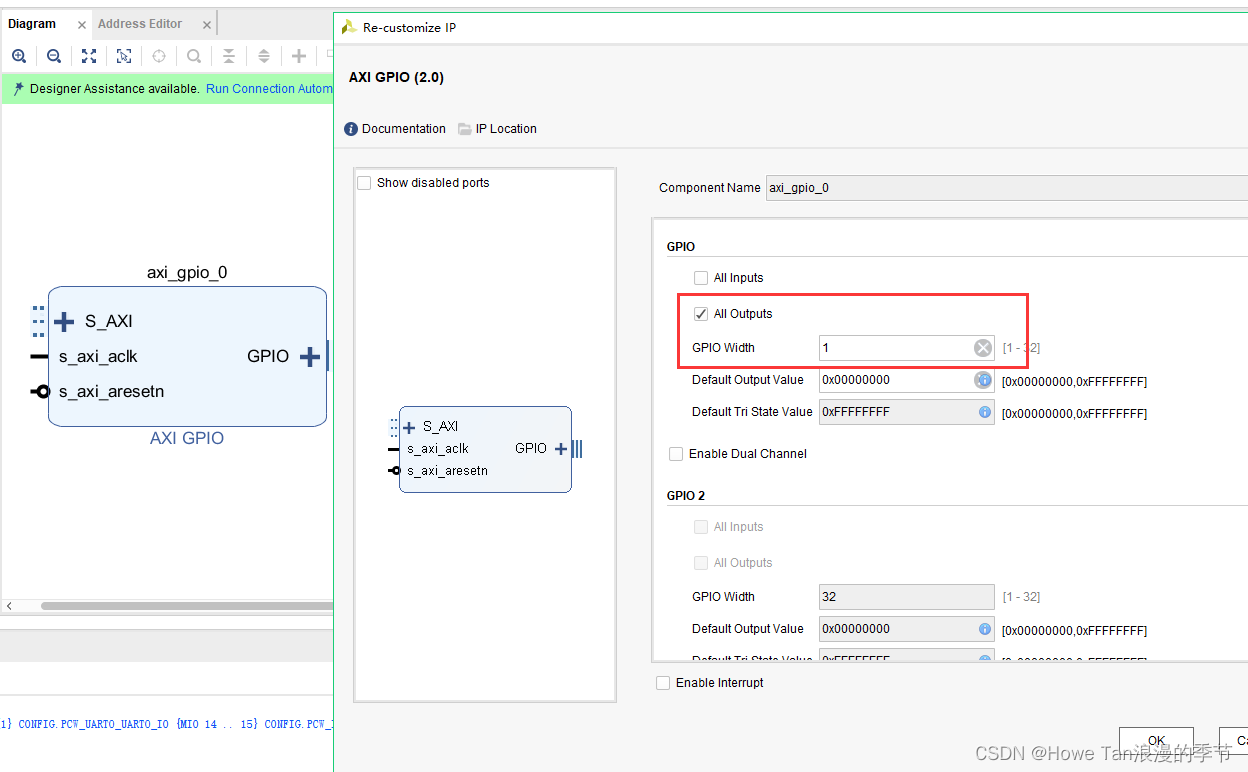
- 添加 AXI GPIO模块,并配置为输出,位宽为1,用于第一路 RS485的 DE 控制
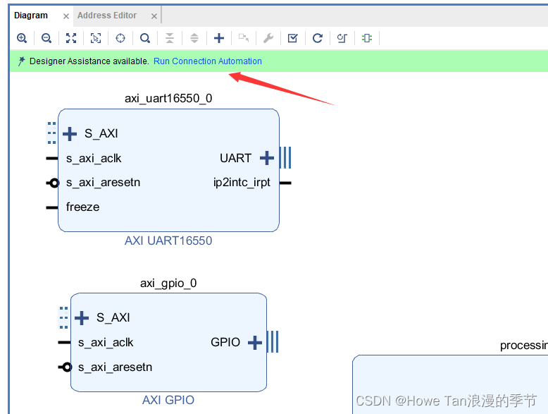
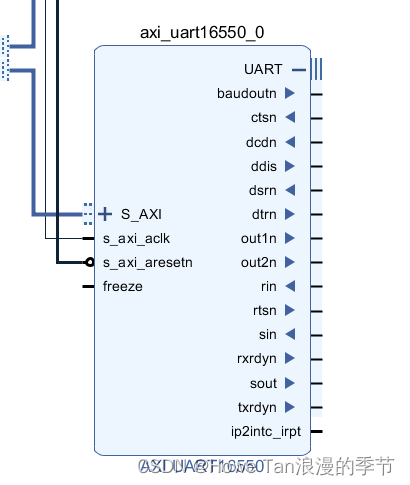
- 添加UART16550模块,用于第一路RS485的数据接口

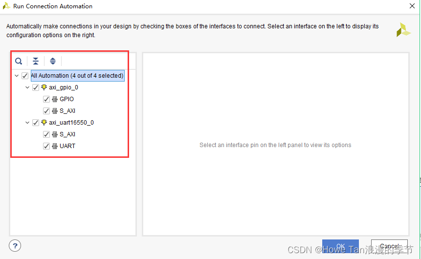
- 自动连接
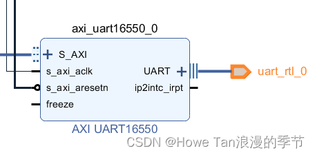
- 删除UART引脚,并展开UART接口
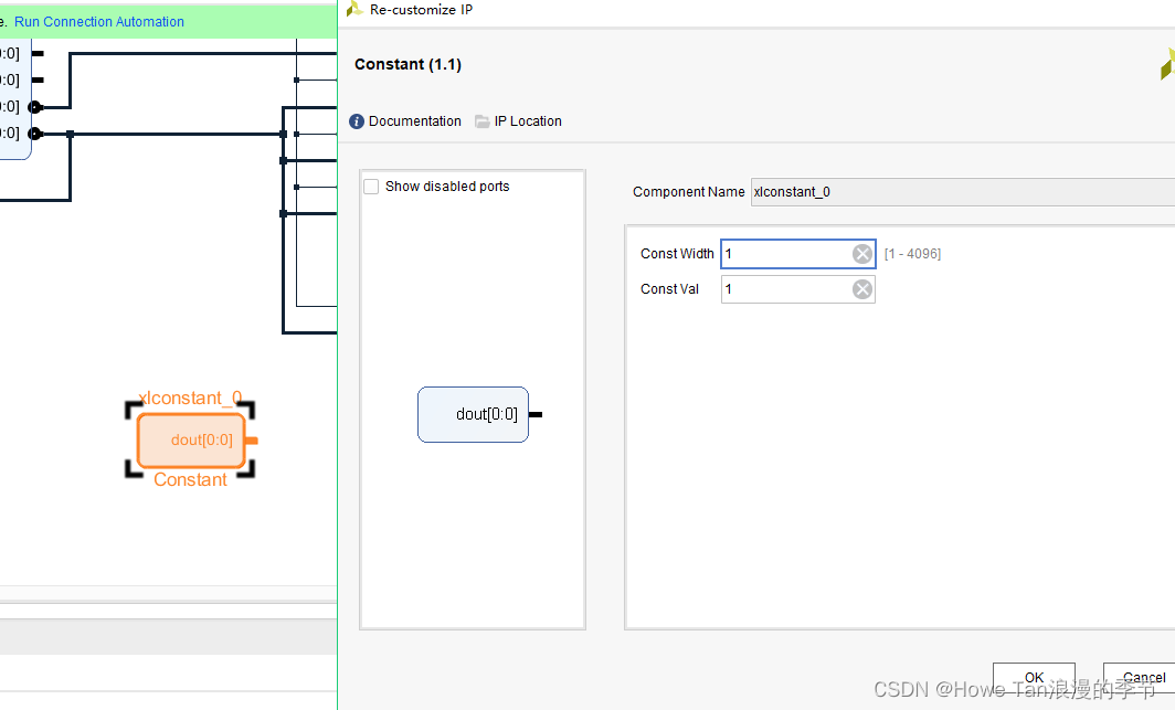
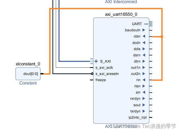
- 添加constant模块,并设置位宽为1,值为1;
- 连接ctsn,rin信号
- 再添加一个constant模块,值设置为0;
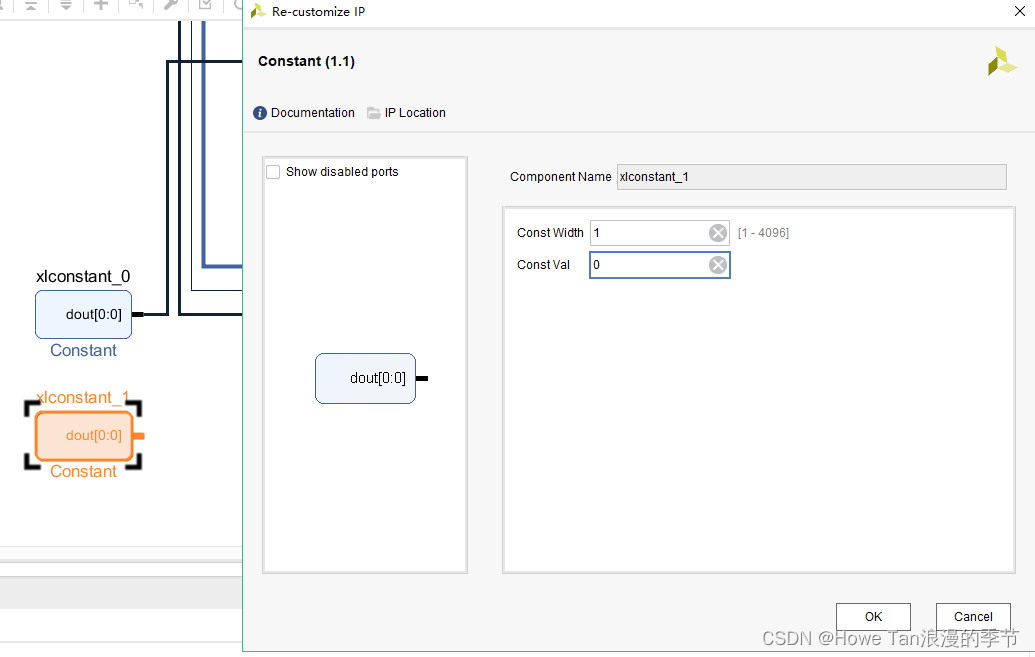
- 连接freeze,dcdn,dsrn信号
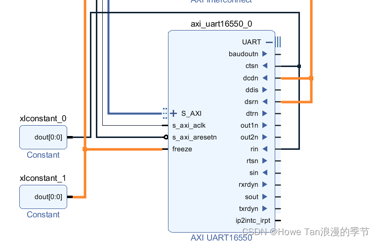
- 将sin和sout引脚导出,修改引脚名字为RS485_0_RXD和RS485_0_TXD;
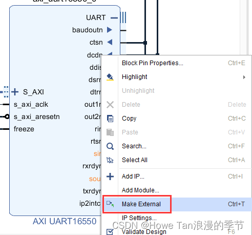
- 并将GPIO的引脚名字修改为RS485_0_DE;至此第一路配置结束。
- 同样的方法开始配置第二路RS485接口;
- 添加concat模块,连接两路中断到pl_ps_irq0;
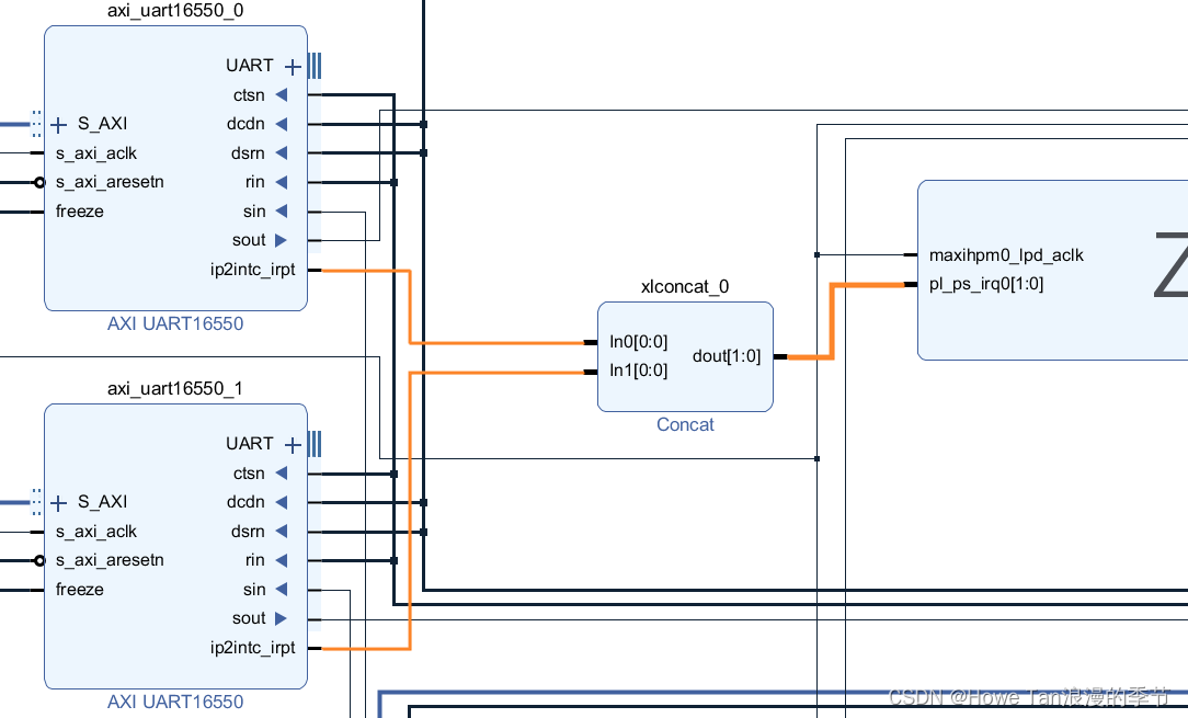
- 自动连接并修改第二路的引脚名称;
四:引脚绑定,并生成bitstream
引脚绑定主要为两路RS485的DE,以及TXD和RXD,根据硬件原理图绑定相应引脚,也即添加.xdc文件,然后create HDL Wrapper以及Generate Output Products,最后编译并生成bitstream

五:导出硬件平台信息,然后在SDK里新建一个helloworld工程;
六:将板子的A1和B1 以及A2,B2分别与外部串口通信工具连接,也即用485转USB连接电脑。
七:PS端代码:废话少说直接上代码:
#include <stdio.h>
#include "xil_printf.h"
#include "xgpio.h"
#include "xuartns550.h"
#include "sleep.h"
#include "RS485_process.h"


XUartNs550Format UartNs550Format =
{
		115200,
		XUN_FORMAT_8_BITS,
		XUN_FORMAT_NO_PARITY,
		XUN_FORMAT_1_STOP_BIT
};

#define DE0_DEVICE_ID	XPAR_GPIO_0_DEVICE_ID
#define DE1_DEVICE_ID	XPAR_GPIO_1_DEVICE_ID

XGpio rs485_0_de ;
XGpio rs485_1_de ;

XUartNs550 UartNs550_0;
XUartNs550 UartNs550_1;
/*
 * For UART16550 module,The following constant controls the length of the buffers to be sent
 * and received with the UART, this constant must be 16 bytes or less since
 * this is a single threaded non-interrupt driven example such that the
 * entire buffer will fit into the transmit and receive FIFOs of the UART
 */
#define TEST_BUFFER_SIZE 200
u8 SendBuffer[TEST_BUFFER_SIZE];	/* Buffer for Transmitting Data */
u8 RecvBuffer[TEST_BUFFER_SIZE];	/* Buffer for Receiving Data */

u8 *RecvBufferPtr;
volatile u32 TotalRecvCnt;
char  RS485_Recv_flag = 0;


int main()
{
	int Status;
	RecvBufferPtr = RecvBuffer;

    Status = RS485_Init();
    /* wait 1ms */
	usleep(1000) ;

	memset(RecvBuffer, 0, TEST_BUFFER_SIZE) ;
    while(1)
    {
        RS485_Recv_Data();

        RS485_Send_Out(char *Send_data,int n);

    }


    return 0;
}

int RS485_Send_Out(char *Send_data,int n)
{
	/* RS485_1 TX */
	XGpio_DiscreteWrite(&rs485_1_de, 1, 1);
    if(RS485_Recv_flag == 1){
    	for(int j = 0;j<n;j++)
	    {
		    XUartNs550_SendByte(UartNs550_1.BaseAddress, Send_data[j]);
	    }
        RS485_Recv_flag = 0;
    }
	return 0;
}
void RS485_Recv_Data()
{
	u32 ReceivedCount = 0;
	u8 flag = 0;
	/* RS485_0 RX FROM*/
	XGpio_DiscreteWrite(&rs485_0_de, 1, 0);

	if(XUartNs550_IsReceiveData(UartNs550_0.BaseAddress))
	{
		ReceivedCount = XUartNs550_Recv(&UartNs550_0, RecvBufferPtr, 1);			//接收一下
		TotalRecvCnt += ReceivedCount ;
		RecvBufferPtr += ReceivedCount ;
	}
	if (TotalRecvCnt== TEST_BUFFER_SIZE) {
		RecvBufferPtr = RecvBuffer;
		TotalRecvCnt = 0;
		ReceivedCount = 0;
		flag =1;
	}
	if(flag ==1){
		for(int j = 0; j<TEST_BUFFER_SIZE;j++)
		{
			SendBuffer[j] = RecvBuffer[j];
		}
		flag = 0;
        RS485_Recv_flag = 1;
	}

}

int RS485_Init()
{
	int Status;
	/* Initial RS485_0 DE */
	PLGpioInitial(&rs485_0_de, DE0_DEVICE_ID) ;
	/* Initial RS485_1 DE */
	PLGpioInitial(&rs485_1_de, DE1_DEVICE_ID) ;

	xil_printf("Start UART485 Send Test!\r\n");

	/* Initial UART16550 which connected to RS485_0 */
	Status = UartNs550Initial(XPAR_AXI_UART16550_0_DEVICE_ID, &UartNs550_0) ;
	if (Status != XST_SUCCESS) {
		xil_printf("RS485_0 Initial Failed!\r\n");
		return XST_FAILURE;
	}
	/* Initial UART16550 which connected to RS485_1 */
	Status = UartNs550Initial(XPAR_AXI_UART16550_1_DEVICE_ID, &UartNs550_1) ;
	if (Status != XST_SUCCESS) {
		xil_printf("RS485_1 Initial Failed!\r\n");
		return XST_FAILURE;
	}

	/*Set rs485_1 to tx*/
	XGpio_DiscreteWrite(&rs485_1_de, 1, 1);
	/* Set rs485_0 to rx*/
	XGpio_DiscreteWrite(&rs485_0_de, 1, 0);

	return 0;
}

int PLGpioInitial(XGpio *GpioInstPtr, u16 DeviceId)
{
	int Status ;

	/* initial gpio */
	Status = XGpio_Initialize(GpioInstPtr, DeviceId) ;
	if (Status != XST_SUCCESS)
		return XST_FAILURE ;

	/* set gpio as output */
	XGpio_SetDataDirection(GpioInstPtr, 1, 0x0);

	return XST_SUCCESS ;
}


int UartNs550Initial(u16 DeviceId, XUartNs550 *UartNs550)
{
	int Status;
	u16 Options;

	/*
	 * Initialize the UART Lite driver so that it's ready to use,
	 * specify the device ID that is generated in xparameters.h
	 */
	Status = XUartNs550_Initialize(UartNs550, DeviceId);
	if (Status != XST_SUCCESS) {
		return XST_FAILURE;
	}

	/*
	 * Perform a self-test to ensure that the hardware was built  correctly
	 */
	Status = XUartNs550_SelfTest(UartNs550);
	if (Status != XST_SUCCESS) {
		return XST_FAILURE;
	}

	/*
	 * Enable the local loopback so data that is sent will be received,
	 * and keep the FIFOs enabled
	 */
	Options = XUN_OPTION_FIFOS_ENABLE;
	XUartNs550_SetOptions(UartNs550, Options);
	/* Set uart mode Baud Rate 115200, 8bits, no parity, 1 stop bit */
	XUartNs550_SetDataFormat(UartNs550, &UartNs550Format);

	return XST_SUCCESS;
}
八:结果总结
在串口助手中利用一个串口发送数据,可以看到另一个串口会打印出数据。
在本次实验中利用开发板PL端的两个RS485接口实现了PS端的控制通信,在代码设置一个RS485口为输出,一个RS485口为数据输入。这样就不用切换使用一个RS485口了。
因为RS485是半双工通信,完全可以利用一个RS485就可以实现数据的输入和输出,只是要翻转一下DE控制引脚,因此本实验只需修改为只使用RS485_0也可,代码里增加每次接收数据设置为接收方向,输出时设置为输出方向,并注意核对串口输出地址为同一个串口下(因为本实验有两个会错乱)。
此外:RS485通信等价于RS422通信的单路,也即RS485设置为输出时,其引脚A,B等同于RS422的T+和T-。设置为输入是,其引脚A,B等同于RS422的R+和R-。因此根据工程需要可以和RS422引脚直用杜邦线连接通信,两路RS485等于一路RS422。这样就不用把RS485频繁切换输入输出方向了。


 1万+
1万+


 被折叠的 条评论
为什么被折叠?
被折叠的 条评论
为什么被折叠?
 到【灌水乐园】发言


