


本文由Markdown编辑器编辑而成。
1.MIP的定义
在前面的技术调研中,已经对MPR(多平面重建)的原理及其在ParaView中的实现进行了基本的介绍。MPR最常用来检查脊椎,因为轴切面的影像只限于有时才能显出椎体,也无法完全显示出椎间盘,然后经过影像的重组,医生便可以更容易地观察出脊椎地位置以及其和其他器官的关系。
在医学影像的三维影像后处理算法中,除了MPR外,还有一种较为常见的算法,名称为MIP(Maximum Intensity Projection),也被称为“最大亮度投影”,是在可视化平面上投射三维空间数据的一种计算机可视化方法。其中,沿着从视点到投影平面的平行光线,各个体素密度值的所呈现的亮度将以某种方式加以衰减,并且最终在投影平面上呈现的是亮度最大的体素。 MIP能反应相应像素的X线衰减值,较小的密度变化也能在MIP图像上显示,能很好地显示血管的狭窄、扩张、充盈缺损及区分血管壁上的钙化与血管腔内的对比剂。
In scientific visualization, a maximum intensity projection (MIP) is a volume rendering method for 3D data that projects in the visualization plane thevoxels with maximum intensity that fall in the way of parallel rays traced from the viewpoint to the plane of projection. This implies that two MIP renderings from opposite viewpoints are symmetrical images if they are rendered using orthographic projection.
This technique is computationally fast, but the 2D results do not provide a good sense of depth of the original data. To improve the sense of 3D, animations are usually rendered of several MIP frames in which the viewpoint is slightly changed from one to the other, thus creating the illusion ofrotation. This helps the viewer’s perception to find the relative 3D positions of the object components. However, since the projection is orthographicthe viewer cannot distinguish between left or right, front or back and even if the object is rotating clockwise or anti-clockwise.
MIP is used for the detection of lung nodules in lung cancer screening programs which utilise computed tomography scans. MIP enhances the 3D nature of these nodules, making them stand out from pulmonary bronchi and vasculature.
MIP imaging was invented for use in Nuclear Medicine by Jerold Wallis, MD, in 1988, and subsequently published in IEEE Transactions in Medical Imaging.[1] In the setting of Nuclear Medicine, it was originally called MAP (Maximum Activity Projection). Additional information can be found in other articles by the same author.
Use of depth weighting during production of rotating cines of MIP images can avoid the problem of difficulty of distinguishing right from left, and clockwise vs anti-clockwise rotation. MIP imaging is used routinely by physicians in interpreting Positron Emission Tomography (PET) or Magnetic Resonance Angiography studies.
https://en.wikipedia.org/wiki/Maximum_intensity_projection
2.ParaView中实现MIP的调节
MPR的调节,主要是通过利用ParaView中的Slicer滤波器,沿不同的方向去切割原来的体数据,然后将切割出的二维图像显示在界面中,即可以呈现出效果。
然后,与MPR不同的是,MIP是一种不同的光线投射的方法,它是属于Mapper的一个属性blendMode。但是,这个属性在ParaView的界面中并没有提供可以直接修改的选项。
通过在网上查找相关的解决方案,结合对ParaView的源码的分析,最终通过将ParaView的vtkImageVolumeRepresentation类增加了一个public函数,setBlendMode(),进而通过这个函数改变其内部的protect类型的成员变量vtkSmartVolumeMapper的blendMode属性值,实现了MIP的功能。
以下是具体的实现步骤。
2.1 获取并编译ParaView5.0源代码
由于需要修改项目源码才能实现所需要的功能,因此第一步便是编译ParaView的源代码。
ParaView发布的最新稳定版本是5.0。源码的下载地址为:
http://www.paraview.org/download/。
然后根据官网中介绍的如何编译ParaView源码的文档,依次进行相关选项的修改。
http://www.paraview.org/Wiki/ParaView:Build_And_Install
编译环境如下:
| 编译环境 | 版本号 |
|---|---|
| Linux | CentOS 7.0 |
| QT | 4.8.2 |
| Python | 2.7 |
| CMake | 3.4.1 |
| Eclipse | CDT4 - Unix Makefiles |
| gcc | 4.8.5(系统自带) |
如上表所示,编译的操作系统为Linux CentOS 7.0。QT为4.8.2,Python为2.7。
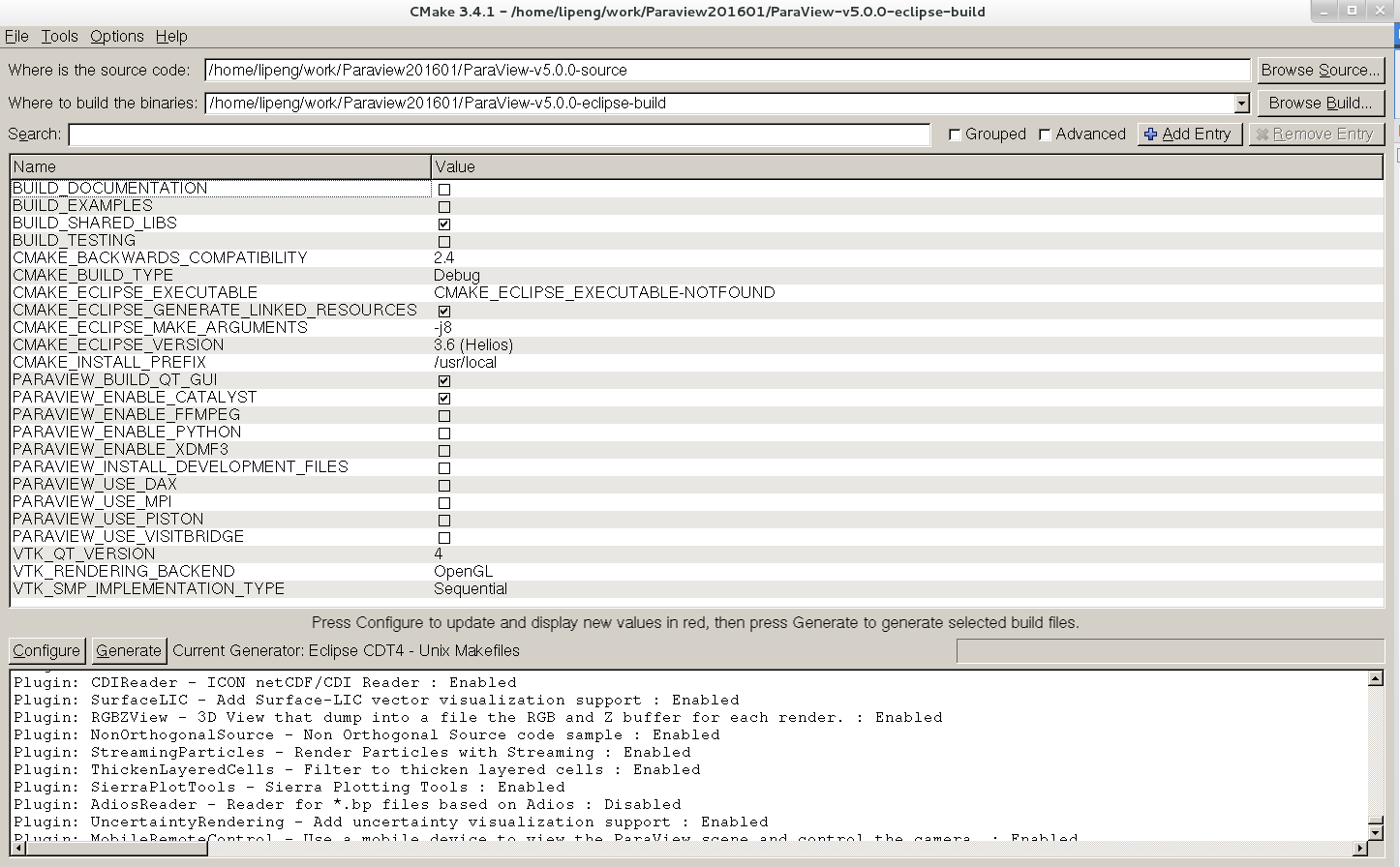
打开CMake的界面,选择源码位置和编译的输出位置后,编译器采用系统自带的gcc编译器,工程构建采用Eclipse CD4-Unix Makefiles。
在CMake的各编译选项中,填写QMAKE的可执行文件路径,关闭BUILD_TESTING项。暂且禁用PARAVIEW_ENABLE_MPI, PYTHON选项。(注意这里是与官网的步骤中不相同的。因为我在实际的编译中,如果开启编译测试项和允许Python后,在编译生成的项目工程过程中,始终无法通过编译。)
下图是我本机CMake生成工程时的选项界面。
CMake构建工程完毕后,接下来采用Eclipse进行工程的编译。由于Eclipse本身并没有自带C++的编译器,因此首先需要下载CDT的插件到Eclipse IDE中,这样便可以利用Eclipse进行C++工程的编译了。关于这个过程,可以参考如下链接。
https://software.intel.com/en-us/articles/intel-c-compiler-for-linux-using-intel-compilers-with-the-eclipse-ide-pdf
生成工程后,在Eclipse进行工程的编译。在内存为8G,CPU为8核全部开启的情况下,第一次编译完成约需要15~20min左右的时间。如图2所示为Eclipse编译完成后的界面。
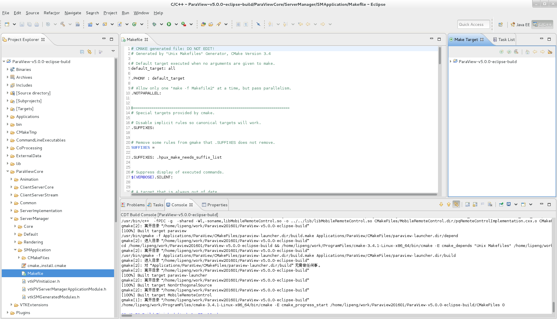
项目编译完成后,在bin文件夹下会生成paraview的可执行程序,在lib文件夹下会生成相应的.a和.so的链接库。
到这个时候,源代码的编译工作就完成了。
2.2 修改相关xml文件,在界面上显示改变blendMode的控件
为了使用户可以在界面进行blendMode的切换,需要在界面中增加一个选择blendMode的combo Box。
在ParaView的源码中,所有关于filters, views, representations, rendering, readers, writers等的设置都是在xml中完成的。Xml文件的存放地址为:
ParaView-v5.0.0-source/ParaViewCore/ServerManager/SMApplication/Resources/ 的目录下。
在该路径下,选择并打开views_and_representations.xml文件。
由于读入的.vtk数据类型是以UniformGridRepresentation的形式进行显示的。它对应的vtk类名和代理该类的代理名称为:
class=”vtkImageVolumeRepresentation”,
proxyname=”UniformGridVolumeRepresentation”.
因此,需要分别修改这个vtk类和这个代理的属性。
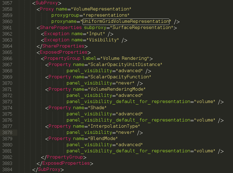
为了使该代理能够增加setBlendMode()的接口,需要在exposedProperties中增加一个BlendMode的Property。代码修改如下:
    <Property name=”BlendMode”
            panel_visibility=”advanced”
            panel_visibility_default_for_representation=”volume” />
修改后的xml截图如下:
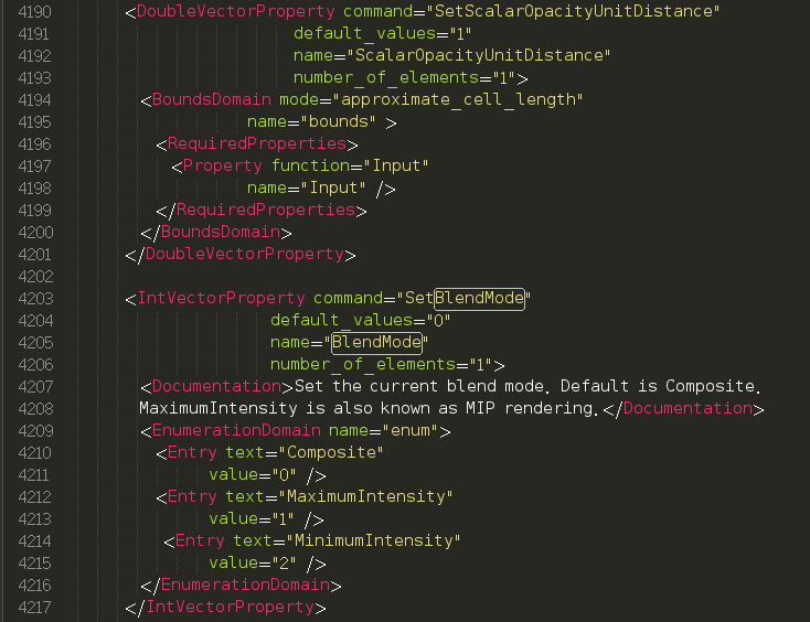
然后,需要为BlendMode设置相应的备选项。BlendMode有三个值,分别是composite, MaximumIntensity和 MinimumIntensity.
在xml中关于代理UniformGridVolumeRepresentation进行各properties的值进行初始化的时候,增加BlendMode的初始化。
<IntVectorProperty command="SetBlendMode"
                         default_values="0"
                         name="BlendMode"
                         number_of_elements="1">
        <Documentation>Set the current blend mode. Default is Composite.MaximumIntensity is also known as MIP rendering.  </Documentation>
        <EnumerationDomain name="enum">
          <Entry text="Composite"
                 value="0" />
          <Entry text="MaximumIntensity"
                 value="1" />
           <Entry text="MinimumIntensity"
                 value="2" />
        </EnumerationDomain>
</IntVectorProperty>
增加BlendMode的初始化后的xml的代码段截图如下:
注意增加的这段代码,其中:
command=”SetBlendMode”必须是代理对应的vtk类
vtkImageVolumeRepresentation的一个public函数才行,否则在编译项目的时候会提示找不到这个函数。
但是,在源代码中,vtkImageVolumeRepresentation类没有这个public的函数。因此接下来需要修改这个类的代码。
2.3 修改相关vtk类,实现MIP调节功能
通过在VTK的官网上查看vtk的类结构图,setBlendMode()是vtkVolumeMapper的virtual类型的public型成员函数,而在vtkImageVolumeRepresentation含有protect类型的vtkSmartVolumeMapper的成员变量实例。而vtkSmartVolumeMapper是继承于vtkVolumeMapper的,因此它可以访问基类的setBlendMode()的成员函数。
以下是vtk中关于vtkVolumeMapper和它派生类的类图。
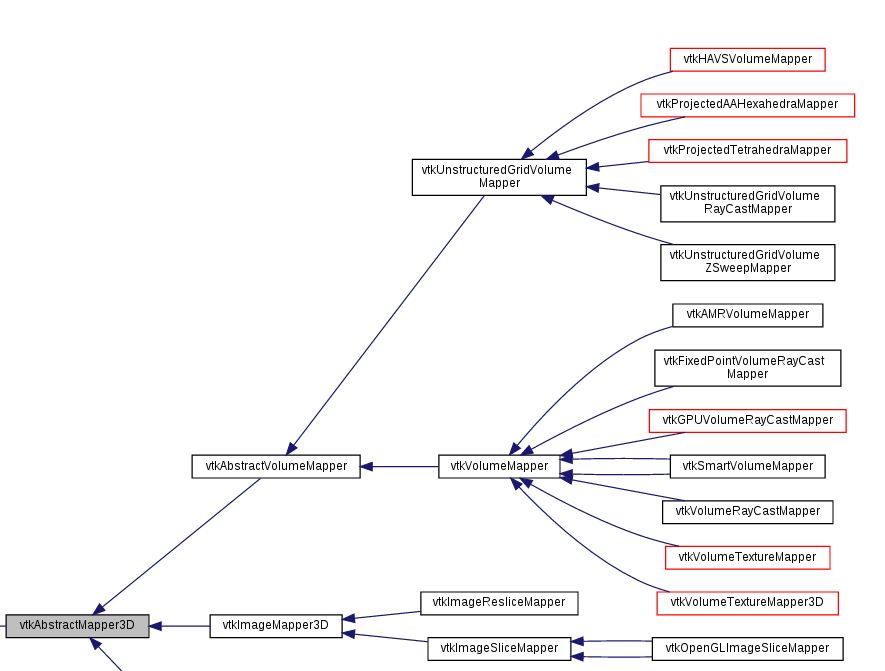
明确了vtk类需要修改的地方,接下来就进行相应的修改。vtkImageVolumeRepresentation类在源代码中的位置在:
ParaView-v5.0.0-source/ParaViewCore/ClientServerCore/Rendering/vtkImageVolumeRepresentation.h, 和vtkImageVolumeRepresentation.cxx。
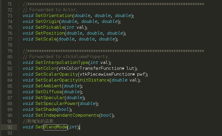
在该类的头文件中,增加一个SetBlendMode()的public函数。
  void SetInterpolationType(int val);
  void SetColor(vtkColorTransferFunction* lut);
  void SetScalarOpacity(vtkPiecewiseFunction* pwf);
  void SetScalarOpacityUnitDistance(double val);
  void SetAmbient(double);
  void SetDiffuse(double);
  void SetSpecular(double);
  void SetSpecularPower(double);
  void SetShade(bool);
  void SetIndependantComponents(bool);
  //新增加的函数.
  void SetBlendMode(int);
头文件修改后的截图如下:
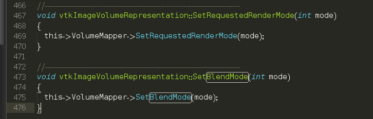
源文件的修改,则是将该SetBlendMode函数的参数值,传给该类的成员变量vtkSmartVolumeMapper* VolumeMapper。这样当用户在界面上选择不同的blendMode后,便会相应修改volumeMapper的blendMode,从而实现不同的投影方式。
在源文件的最后增加代码:
//----------------------------------------------------------
void vtkImageVolumeRepresentation::SetBlendMode(int mode)
{
  this->VolumeMapper->SetBlendMode(mode);
}
源文件修改后的截图为:
3. MIP的效果图
根据第2节中的步骤,修改相应的xml和.h, .cxx文件后,再次利用CMake构建工程,并且在Eclipse中编译代码。在编译完成后的bin文件夹中打开paraview的可执行程序,然后进行MIP功能的展示。
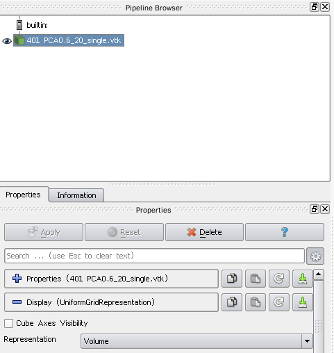
加载完体数据后,选择Apply,并且将Representation选择为Volume类型,如图所示:
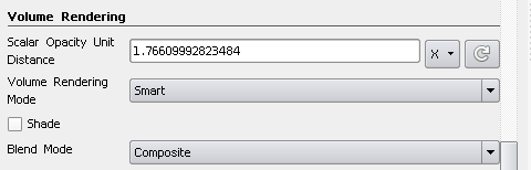
此时,往下拉滚动条,可以看到在Volume Rendering的标签页中,新增加了一个名称为blendMode的combo Box控件。该控件有三个值,默认是composite。如图所示:
此时,体绘制的效果图为:
默认的投影方式(composite)下的MR图像为:
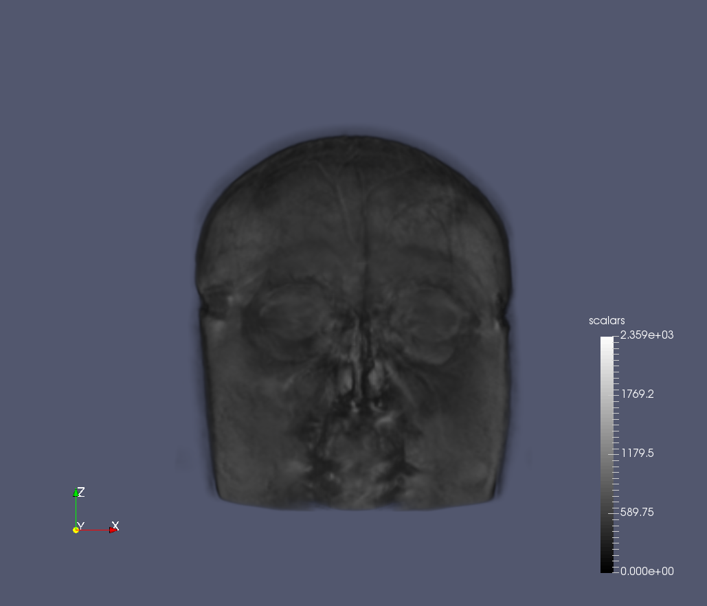
MR的composite模式下的成像
选择其中的第二项MaximumIntensity后,显示的结果变为:
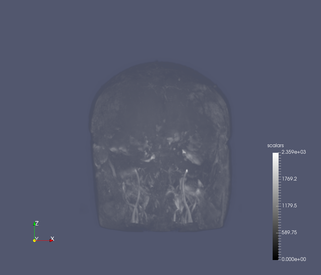
MR的maximum intensity projection模式下的成像
从图中可以看到沿垂直于界面的平行光线中,密度最大的点,也即实现了最大密度投影的效果。
另一组测试数据的效果图为:
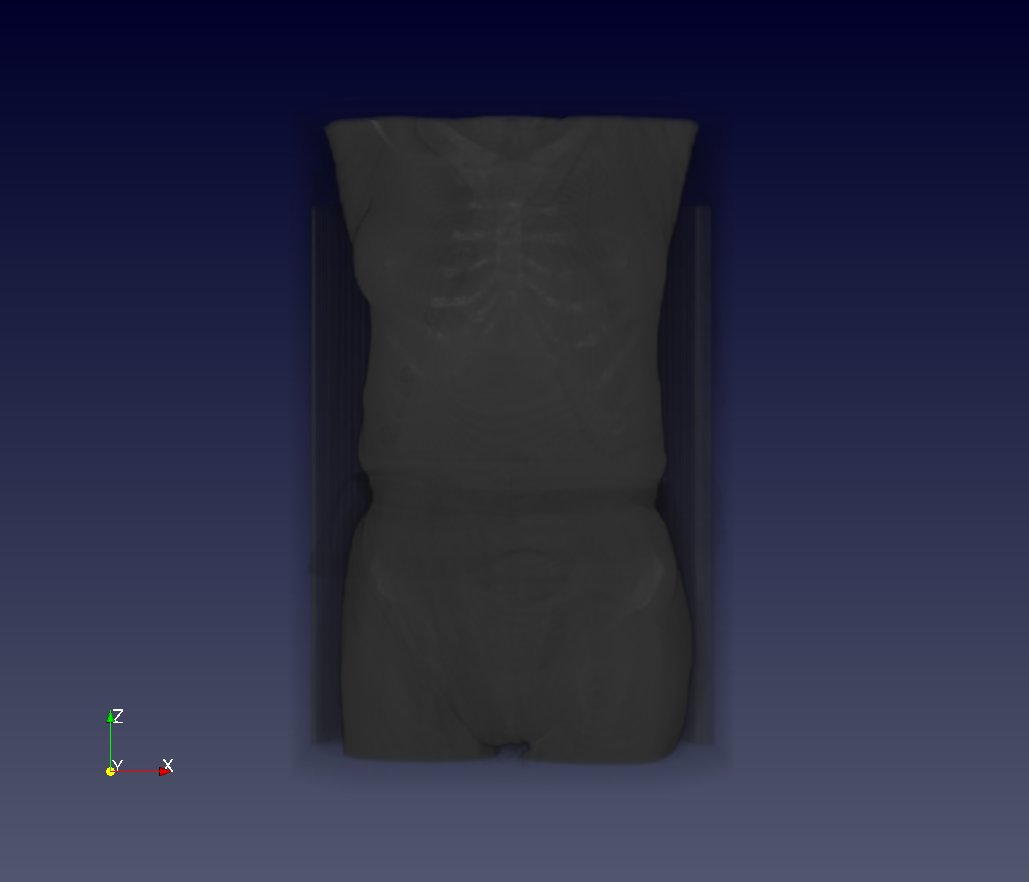
CT的composite模式下的成像
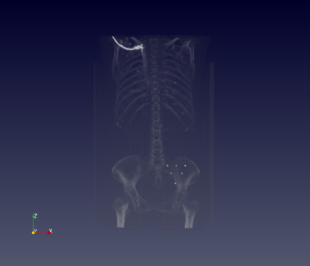
CT的MIP模式下的成像
完。


 1576
1576

 被折叠的 条评论
为什么被折叠?
被折叠的 条评论
为什么被折叠?
 到【灌水乐园】发言


