


这是练英语写作的,中文在下面。
1、Simple Demo
We can operate the GPIO of NodeMCU like Arduino,Code block-1 is a simple demo gave by the official website.
For more you can see http://nodemcu.readthedocs.io/en/master/en/modules/gpio/
pin = 1--Define the number of GPIO which to operate
gpio.mode(pin,gpio.OUTPUT)--Define the mode of GPIO to output
gpio.write(pin,gpio.HIGH)--Output a high level
gpio.mode(pin,gpio.INPUT)--Define the mode of GPIO to input
print(gpio.read(pin))--Read the input signal,return a number, 0 = low, 1 = high
The syntax of GPIO mode definition is as follows:
gpio.mode(pin,mode[,pullup])
Parameters
pinpin to configure, IO indexmodeone of gpio.OUTPUT, gpio.OPENDRAIN, gpio.INPUT, or gpio.INT (interrupt mode)pullupgpio.PULLUP enables the weak pull-up resistor; default is gpio.FLOAT
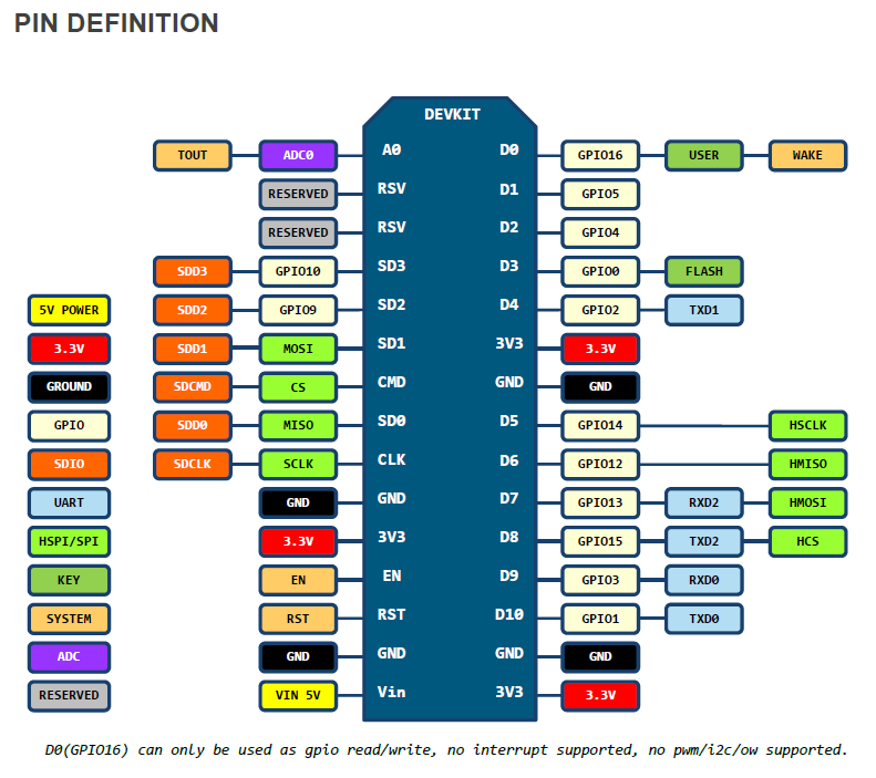
2、Pin Map
The Figure-1 (NODEMCU_DEVKIT_V1.0_PINMAP.png) is the GPIO map between NodeMCU and ESP8266.
3、GPIO Index
The Table-1 is the map between pin index and ESP8266 GPIO. Combined with Figure-1 and Table-1,we can get the pin-index corresponding the hardware GPIO.
—————————————————————————————————————————
上面是练英语写作的,欢迎吐槽 。中文如下:
1、简单例程
我们可以像Arduino一样只需要几行代码就能方便地操作NodeMCU的GPIO。下面是官方的示例代码,更多请查看
http://nodemcu.readthedocs.io/en/master/en/modules/gpio/
示例代码code block-1
参考http://nodemcu.com/index_cn.html
pin = 1
gpio.mode(pin,gpio.OUTPUT)
gpio.write(pin,gpio.HIGH)
gpio.mode(pin,gpio.INPUT)
print(gpio.read(pin))gpio.mode(pin,gpio.OUTPUT)--输出模式
gpio.write(pin,gpio.HIGH)--输出高电平
gpio.mode(pin,gpio.INPUT)--输入模式
print(gpio.read(pin))--读取输入信号,返回0或1
GPIO模式定义语法如下:
gpio.mode(pin,mode[,pullup])
参数
pinIO 口序号mode可以是gpio.OUTPUT, gpio.OPENDRAIN, gpio.INPUT, 或者 gpio.INT (中断模式)pullup支持gpio.PULLUP上拉模式;默认为 gpio.FLOAT浮空模式
2、引脚映射
NodeMCU与ESP8266端口对应关系Figure-1
3、GPIO序号
GPIO序号与ESP8266引脚对应关系Table-1
| IO index | ESP8266 pin | IO index | ESP8266 pin |
|---|---|---|---|
| 0 [*] | GPIO16 | 7 | GPIO13 |
| 1 | GPIO5 | 8 | GPIO15 |
| 2 | GPIO4 | 9 | GPIO3 |
| 3 | GPIO0 | 10 | GPIO1 |
| 4 | GPIO2 | 11 | GPIO9 |
| 5 | GPIO14 | 12 | GPIO10 |
| 6 | GPIO12 |
【转载请注明出处:http://blog.csdn.net/leytton/article/details/51646624】
PS:如果此文对您有所帮助,请点个赞让我知道哦~


 2504
2504


 被折叠的 条评论
为什么被折叠?
被折叠的 条评论
为什么被折叠?
 到【灌水乐园】发言


