


路由
实验步骤:
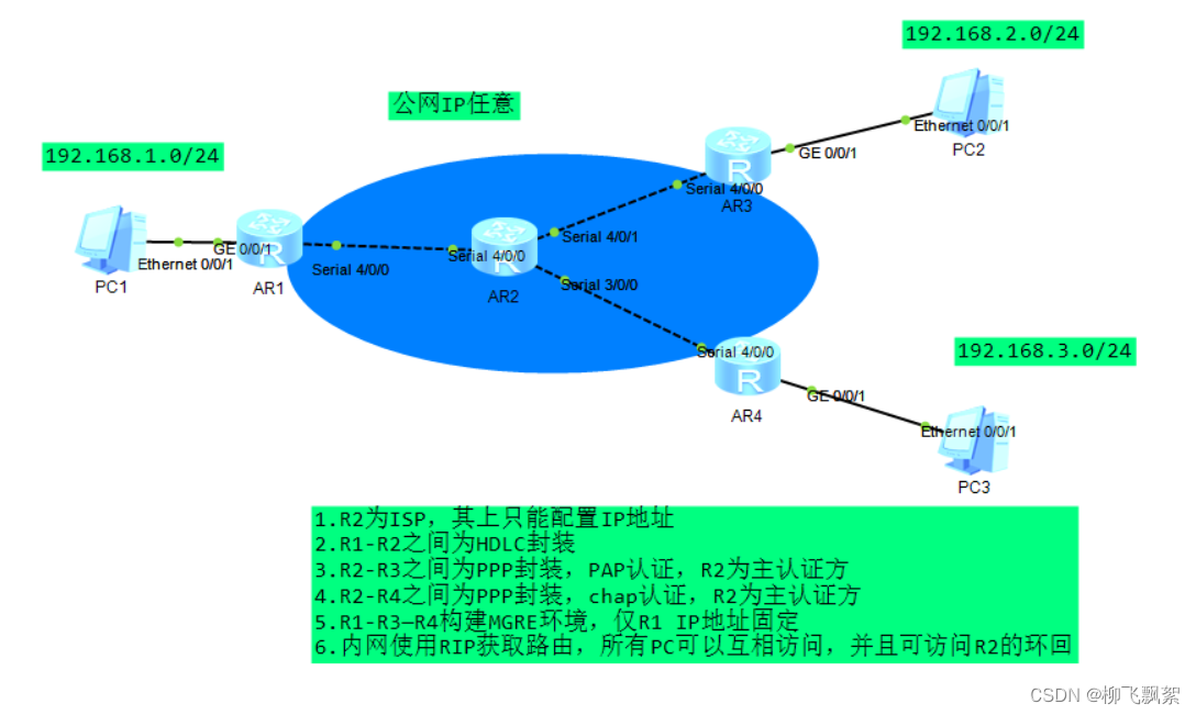
第一步:IP地址规划
PC1:192.168.1.2 24 网关:192.168.1.1 24
PC2:192.168.2.2 24 网关:192.168.2.1 24
PC3:192.168.3.2 24 网关:192.168.3.1 24
R1-R2: R1:12.1.1.1 24 R2:12.1.1.2 24
R2-R3: R2:23.1.1.1 24 R3:23.1.1.2 24
R2-R4: R2:24.1.1.1 24 R4:24.1.1.2 24
R2环回:2.2.2.2 24
第二步:IP地址配置
R1:
[R1]int g0/0/1
[R1-GigabitEthernet0/0/1]ip add 192.1.1.1 24
[R1-GigabitEthernet0/0/1]int s4/0/0
[R1-Serial4/0/0]ip add 12.1.1.1 24
R2:
[R2]int s4/0/0
[R2-Serial4/0/0]ip add 12.1.1.2 24
[R2-Serial4/0/0]int s4/0/1
[R2-Serial4/0/1]ip add 23.1.1.1 24
[R2-Serial4/0/1]int s3/0/0
[R2-Serial3/0/0]ip add 24.1.1.1 24
[R2]int LoopBack 0
[R2-LoopBack0]ip add 2.2.2.2 24
R3:
[R3]int s4/0/0
[R3-Serial4/0/0]ip add 23.1.1.2 24
[R3-Serial4/0/0]int g0/0/1
[R3-GigabitEthernet0/0/1]ip add  192.168.2.1 24
R4:
[R4]int g0/0/1
[R4-GigabitEthernet0/0/1]ip add 192.168.3.1 24
[R4-GigabitEthernet0/0/1]int s4/0/0
[R4-Serial4/0/0]ip add 24.1.1.2 24
第三步:HDLC封装
R1:
[R1]inter s4/0/0
[R1-Serial4/0/0]link-protocol hdlc
R2:
[R2]interface s4/0/0
[R2-Serial3/0/0]link-protocol hdlc
第四步:PAP认证
主认证方配置:
[R2]aaa
[R2-aaa]local-user huawei password cipher 123456
[R2-aaa]local-user huawei service-type ppp
[R2-aaa]int s4/0/1
[R2-Serial4/0/1]ppp authentication-mode pap
被认证方配置:
[R3]int s4/0/0
[R3-Serial4/0/0]ppp pap local-user huawei password cipher 123456
第五步:chap认证
主认证方配置:
[R2]aaa
[R2-aaa]local-user huawei password cipher 123456
[R2-aaa]local-user huawei service-type ppp
[R2]interface s3/0/0
[R2-Serial3/0/0]ppp authentication-mode chap
被认证方配置:
[R4]interface s4/0/0
[R4-Serial4/0/0]ppp chap user huawei
[R4-Serial4/0/0]ppp chap password cipher 123456
第六步:配置缺省路由
[R1]ip route-static 0.0.0.0 0 12.1.1.2
[R3]ip route-static 0.0.0.0 0 23.1.1.2
[R4]ip route-static 0.0.0.0 0 24.1.1.2
第七步:NAT
R1:
[R1]acl 2000
[R1-acl-basic-2000]rule 1 permit source any
[R1-acl-basic-2000]int s4/0/0
[R1-Serial4/0/0]nat outbound 2000
R3:
[R3]acl 2000
[R3-acl-basic-2000]rule 1 permit source any
[R3-acl-basic-2000]int s4/0/0
[R3-Serial4/0/0]nat outbound 2000
R4:
[R4]acl 2000
[R4-acl-basic-2000]rule 1 permit source any
[R4-acl-basic-2000]int s4/0/0
[R4-Serial4/0/0]nat outbound 2000
第八步:R1-R3-R4构建MGRE环境
R1:
[R1]interface Tunnel 0/0/0
[R1-Tunnel0/0/0]ip add 10.1.1.1 24
[R1-Tunnel0/0/0]tunnel-protocol gre p2mp
[R1-Tunnel0/0/0]source 12.1.1.1
[R1-Tunnel0/0/0]nhrp network-id 100
R3:
[R3]interface Tunnel 0/0/0
[R3-Tunnel0/0/0]ip add 10.1.1.2 24
[R3-Tunnel0/0/0]tunnel-protocol gre p2mp
[R3-Tunnel0/0/0]source s4/0/0
[R3-Tunnel0/0/0]nhrp entry 10.1.1.1 12.1.1.1 register
[R3-Tunnel0/0/0]nhrp network-id 100
R4:
[R4]interface Tunnel 0/0/0
[R4-Tunnel0/0/0]ip add 10.1.1.3 24
[R4-Tunnel0/0/0]tunnel-protocol gre p2mp
[R4-Tunnel0/0/0]source s4/0/0
[R4-Tunnel0/0/0]nhrp entry 10.1.1.1 12.1.1.1 register
[R4-Tunnel0/0/0]nhrp network-id 100
第九步:RIP路由配置
R1:
[R1]rip 1
[R1-rip-1]version 2
[R1-rip-1]network 192.168.1.0
[R1-rip-1]network 10.0.0.0
注意: MGRE 环境下 RIP 需要开启伪⼴播和关闭⽔平分割
[R1]interface Tunnel 0/0/0
[R1-Tunnel0/0/0]nhrp entry multicast dynamic //开启伪⼴播
[R1-Tunnel0/0/0]undo rip split-horizon //关闭⽔平分割
R3:
[R3]rip 1
[R3-rip-1]version 2
[R3-rip-1]network 192.168.2.0
[R3-rip-1]network 10.0.0.0
R4:
[R4]rip 1
[R4-rip-1]version 2
[R4-rip-1]network 192.168.3.0
[R4-rip-1]network  10.0.0.0
测试:
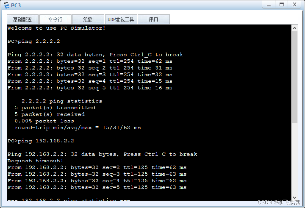
可以访问R2环回以及其他PC


 95
95


 被折叠的 条评论
为什么被折叠?
被折叠的 条评论
为什么被折叠?
 到【灌水乐园】发言


