


一、原理图
新建
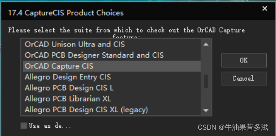
打开Capture CIS 选择 OrCAD Capture CIS >> OK
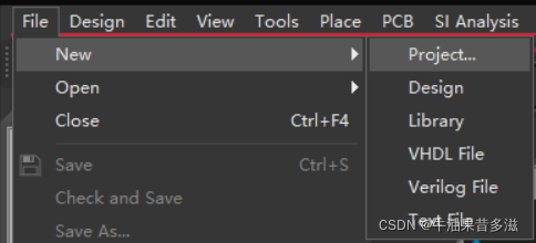
File >> New >> Project,勾选Enable PSpice Simu… >> OK

选择Create based upon an existing >> simple.opj >> OK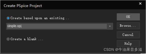
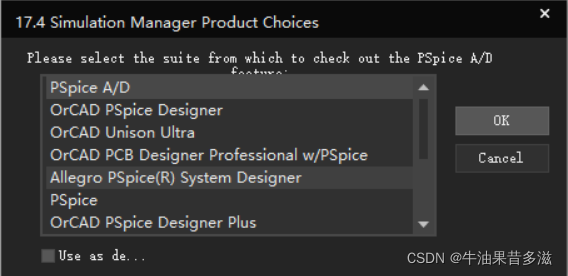
选择PSpice A/D >> OK
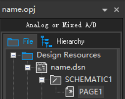
左侧 File >> Design Resources >> name.dsn >> SCHEMATIC1 >> PAGE1 打开图纸
放置元器件
上方 Place >> PSpice Component 或者 右侧 工具栏第二个图标(PSpice库里的才能仿真)
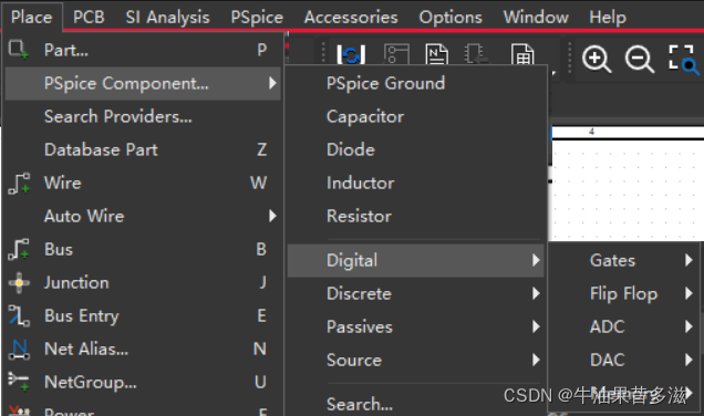
Passive >> R/L/C等
Discrete >> 二极管/MOS管等
Digital >> 门电路/触发器/寄存器/ADC等
快捷键
R旋转
W连线
N设置网络标号,放在延长线上,在和Simulink联合仿真中可作为输入输出
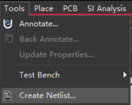
创建网表
上方 Tools >> Create Netlist… >> 确认
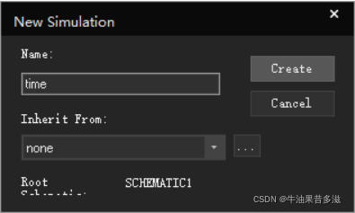
创建仿真参数
上方 PSpice >> New Simulation Profile >> name >> Create >> 改Analysis Type & Run to Time等仿真参数 >> OK
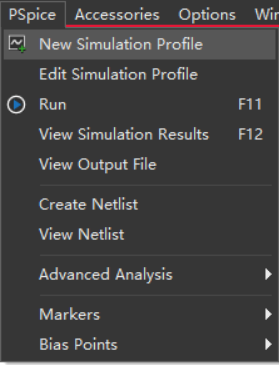
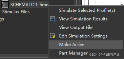
左侧 File >> PSpice Resources >> Simulation Profiles >> SCHEMATIC1-name 右键 >> Make Active

例子
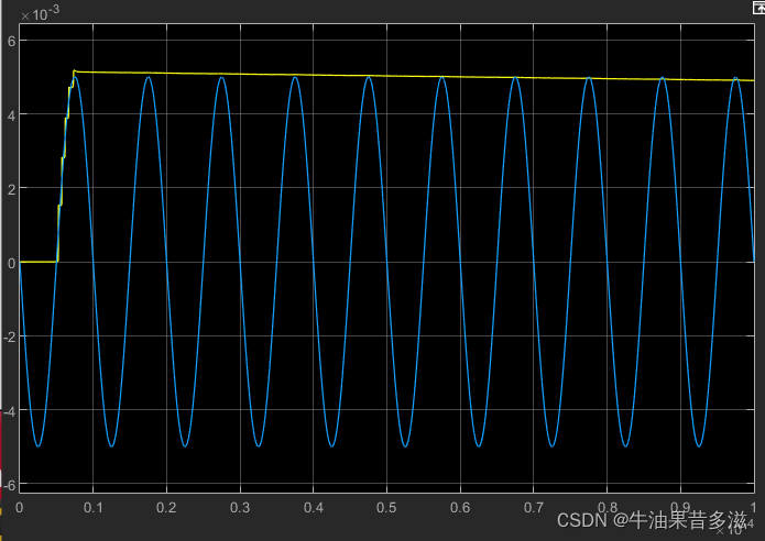
如图所示为一个峰值检测电路
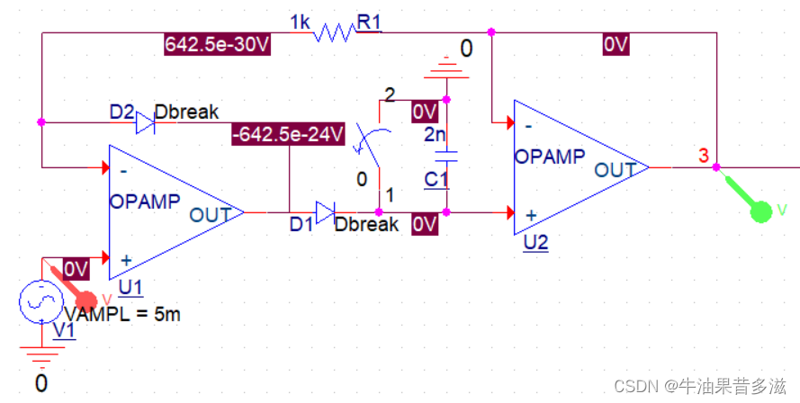
仿真结果

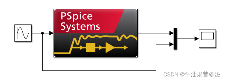
二、Simulink 联合仿真
以管理员身份启动MATLAB >> 命令行窗口运行 regmatlabserver
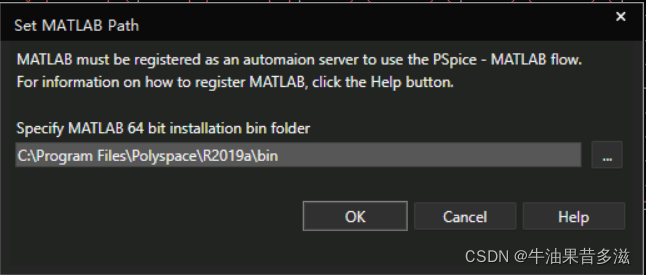
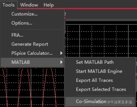
PSpice上方工具栏Tools >> MATLAB >> Set MATLAB Path >> C:\Program Files\Polyspace\R2019a\bin >> OK
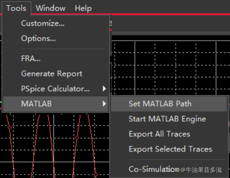
Tools >> MATLAB >> Co-simulation
新建Simulink并保存在和PSpice工程的同一文件夹
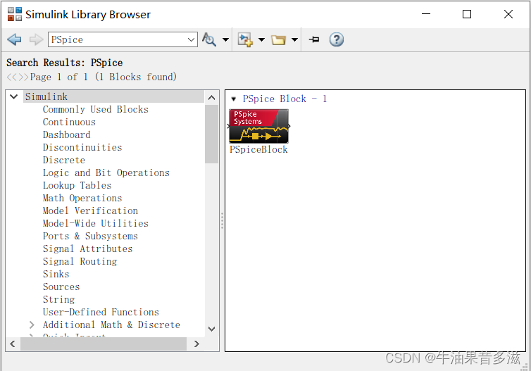
在Library Browser搜索PSpiceBlock >> 双击PSpiceBlock进行设置:
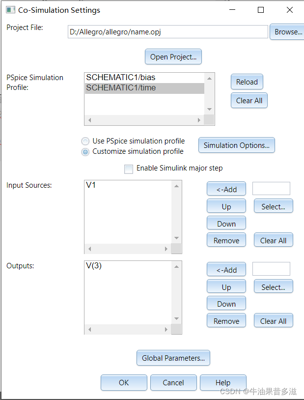
Project File: 选择Capture的工程文件
Input Sources: 例如电源V1 V2 // 设置了网络标号的V(1) V(2)等
Output:设置了网络标号的V(out1) V(out3) 等
例子


 967
967

 被折叠的 条评论
为什么被折叠?
被折叠的 条评论
为什么被折叠?
 到【灌水乐园】发言


