


1 前言
大四上学期有一门硬件课程设计,在此处将这次实践简单的记录一下。本人选择的是第二个题目:抓物机械臂( 6 轴)控制器设计
2 课题目标简介
其实这个题目一步一步完成之后,会发现没有想象中的难,关键还是考验自己的编码能力,以及对前置课程《嵌入式系统》的掌握程度,这里其实只需要详细记得GPIO端口的相关使用,其实就可以基本解决问题了。
可以将整个任务简单的划分为以下的部分:
- 构建IP核(直接使用模板构建)
- 构建软件部分(使用c或者c++语言编写代码)
- 测试运行(验证自己的软件是否正确)
3 具体实现
3.1 构建IP核
- 使用Vavido构建IP核
这部分直接参考老师给的资料构建即可,但是我们实验的时候,很多人都在这里卡了很久,包括我自己,甚至花费了更多的时间,不然实验效果可以更好。所以,如果这一步实在有问题,建议直接找老师要这部分的东西,先写软件部分,或许写着写着,你就会发现之前构建IP核的问题的,不要浪费时间。
- 生成比特流
- 生成顶层模块
- 导出到SDK中,并打开SDK
以上步骤跟着老师嵌入式系统实验中的指导一步一步完成即可(注意部分参数需要根据本实验的PPT做调整),当然,这里需要提醒一点就是,如果打算在个人笔记本上做实验,最好将自己的IDE与实验室的统一一下,实验室的Vivado版本是2019.1,最好使用这个版本。因为从2019.2版本开始,编写软件部分就不是SDK了,或者说,SDK被从Vavido分离了。为了不必要的麻烦,建议直接使用vivado2019.1,这里提供一个安装包(包含license)
链接:https://pan.baidu.com/s/1uURsXxaODH6LMG9sNLAfDw?pwd=2e02
提取码:2e02
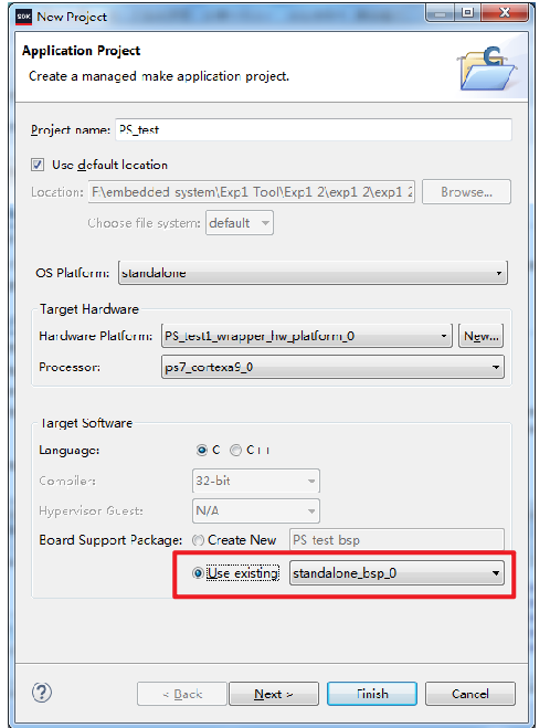
3.2 构建基本的软件开发环境
这一步也是根据老师的指导书完成,其中需要注意几点
- 这里Use Existing
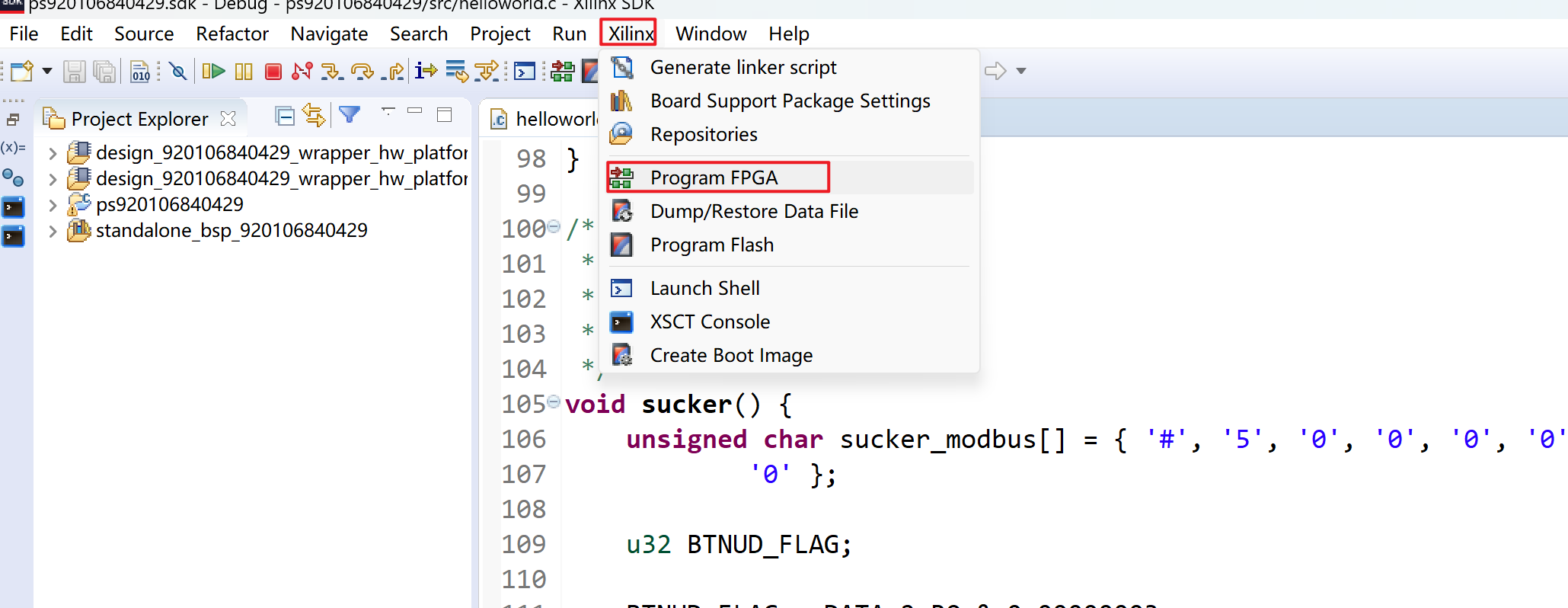
- 在运行羡慕的时候,一定要先做下面这一步,这一步完成之后,会发现开发板上的蓝色小灯亮了。
3.3 软件实现
以上步骤完成之后,就可以开始正常的编写控制机械臂的程序了。
//#include <stdio.h>
//#include "platform.h"
#include "xil_printf.h"

struct AXIE {
	int cur_position;		//轴的当前位置
	int target_position;	//轴的目标位置
	int direction;			//轴的转动方向,-1逆时针转,1顺时针转
};

//设置 MIO引脚地址
#define MIO_PIN_07		(*(volatile unsigned int *)0xF800071C)
#define MIO_PIN_50		(*(volatile unsigned int *)0xF80007C8)
#define MIO_PIN_51		(*(volatile unsigned int *)0xF80007CC)

//设置 GPIO端口方向寄存器地址
#define DIRM_0			(*(volatile unsigned int *)0xE000A204)
#define DIRM_1			(*(volatile unsigned int *)0xE000A244)
#define DIRM_2			(*(volatile unsigned int *)0xE000A284)
#define DIRM_3			(*(volatile unsigned int *)0xE000A2C4)
//设置 GPIO端口输出使能寄存器地址
#define OEN_0			(*(volatile unsigned int *)0xE000A208)
#define OEN_1			(*(volatile unsigned int *)0xE000A248)
#define OEN_2			(*(volatile unsigned int *)0xE000A288)
#define OEN_3			(*(volatile unsigned int *)0xE000A2C8)
//设置 GPIO端口输出寄存器地址
#define DATA_0			(*(volatile unsigned int *)0xE000A040)
#define DATA_1			(*(volatile unsigned int *)0xE000A044)
#define DATA_2			(*(volatile unsigned int *)0xE000A048)
#define DATA_3			(*(volatile unsigned int *)0xE000A04C)
//设置 GPIO端口输入寄存器地址
#define DATA_0_RO		(*(volatile unsigned int *)0xE000A060)
#define DATA_1_RO		(*(volatile unsigned int *)0xE000A064)
#define DATA_2_RO		(*(volatile unsigned int *)0xE000A068)
#define DATA_3_RO		(*(volatile unsigned int *)0xE000A06C)

//设置 UART1引脚地址的宏定义
#define rMIO_PIN_48		(*(volatile unsigned long*)0xF80007C0)
#define rMIO_PIN_49 	(*(volatile unsigned long*)0xF80007C4)
#define rUART_CLK_CTRL 	(*(volatile unsigned long*)0xF8000154)
#define rControl_reg0 	(*(volatile unsigned long*)0xE0001000)
#define rMode_reg0 		(*(volatile unsigned long*)0xE0001004)
//设置 UART1端口波特率等参数地址寄存器的宏定义
#define rBaud_rate_gen_reg0 (*(volatile unsigned long*)0xE0001018)
#define rBaud_rate_divider_reg0 (*(volatile unsigned long*)0xE0001034)
#define rTx_Rx_FIFO0 (*(volatile unsigned long*)0xE0001030)
#define rChannel_sts_reg0 (*(volatile unsigned long*)0xE000102C)

void send_Char_9(unsigned char modbus[]);				//9字节串口发送函数
void send_Char(unsigned char data);						//串口发送函数,一次一个字节
void RS232_Init();										//串口初始化函数

void delay(int i, int n, int m);							//延时函数

struct AXIE axie_1[3];
int reset_flag = 0;								//是否复位标志,=1表示需要复位操作,=0表示不需要复位
int SW0_flag = 0;								//SW0拨动按键标志,=0为初始值,=1时刚下拨,=2时刚上拨
int run_step;											//自动搬物的工序步骤
int run_num = 5;										//自动搬物的设定次数,初值为5(默认值)
int runing_num;											//当前搬物的次数
int conveyorState = 0;
int boxStateFlag = 0;				// 初始的时候
int suckerState = 0;				// 初始的时候没有吸住
int count = 0;						// 记录搬运次数
int auto_armState = 0;					// 机械臂的初始位置,起始位置为0,抓取位置为1,释放位置为2

int conveyor2flag = 0;				// 2号传送带初始位置
int box1State = 0;


// 手动速度
unsigned char leftSpeed = 0x32;
unsigned char rightSpeed = 0x36;

unsigned char auto_leftSpeed = 0x32;
unsigned char auto_rightSpeed = 0x36;

int resetArray[7] = {0};		// 记录当前操作位置

// 控制2号传送带
void conveyor() {
	u32 stateFlag;	// 记录是BTNC的按下信息
	stateFlag = DATA_2_RO & 0x00000010;
	if (stateFlag == 0x00000010 && conveyorState == 0) {
		unsigned char modbus_open[] = { '#', '6', '1', '0', '0', '0', '0', '0',
				'0' };
		send_Char_9(modbus_open);
		delay(1000, 100, 1000);
		conveyorState = 1;
	} else if (stateFlag == 0x00000010 && conveyorState == 1) {
		unsigned char modbus_close[] = { '#', '6', '2', '0', '0', '0', '0', '0',
				'0' };
		send_Char_9(modbus_close);
		delay(1000, 100, 1000);
		conveyorState = 0;
	}
	return;
}

/**
 * 吸盘:
 * 		1) BTNU 抓起
 * 		2) BTND 放下
 */
void sucker() {
	unsigned char sucker_modbus[] = { '#', '5', '0', '0', '0', '0', '0', '0',
			'0' };

	u32 BTNUD_FLAG;

	BTNUD_FLAG = DATA_2_RO & 0x00000003;
	switch (BTNUD_FLAG) {
	case 0x00:

		break;
	case 0x01:	// 按下BTNU,吸住
		if (suckerState == 0) {
			sucker_modbus[2] = '1';
			send_Char_9(sucker_modbus);
			suckerState = 1;
		}
		break;
	case 0x02:	// 按下BTND,放下
		if (suckerState == 1) {
			sucker_modbus[2] = '2';
			send_Char_9(sucker_modbus);
			suckerState = 0;
		}
		break;
	default:
		break;
	}
}

/**
 * 手动模式控制机械臂
 * 使用sw2sw1sw0控制
 */
void maArms() {
	// 指令初始化数组
	unsigned char arm_modbus[9] =
			{ '#', '1', '0', '0', '0', '0', '0', '0', '0' };

	// 记录选择机械臂
	u32 armsFlag;
	armsFlag = DATA_2_RO & 0x00001C00;	// 1.读取sw2sw1sw0

//	unsigned char leftSpeed = 0x32;		// 左转顺时针
//	unsigned char rightSpeed = 0x36;	// 右转逆时针

	u32 direFlag;	// 控制方向
	int Lflag = 0, rflag = 0;

	// 记录BTNR和BTNL
	direFlag = DATA_2_RO & 0x0000000C;

	switch (armsFlag) {
	case 0x00000000:
		DATA_2 = (DATA_2 | 0x00012000) & 0xFFE13FFF;
		break;

	case 0x00001000:	// 001 1号
		DATA_2 = (DATA_2 | 0x00112000) & 0xFFF13FFF;
		if (direFlag == 0x4) { // 左
			arm_modbus[2] = leftSpeed;
			send_Char_9(arm_modbus);

			resetArray[1] ++;
			delay(1000, 100, 100);
		} else if (direFlag == 0x8) { // 右
			arm_modbus[2] = rightSpeed;
			send_Char_9(arm_modbus);

			resetArray[1] --;
			delay(1000, 100, 100);
		}
		break;
	case 0x00000800:	// 010 2号
		DATA_2 = (DATA_2 | 0x00092000) & 0xFFE93FFF;
		if (direFlag == 0x4) { // 左
			arm_modbus[3] = leftSpeed;
			send_Char_9(arm_modbus);

			resetArray[2] ++;
			delay(1000, 100, 100);
		} else if (direFlag == 0x8) { // 右
			arm_modbus[3] = rightSpeed;
			send_Char_9(arm_modbus);

			resetArray[2] --;
			delay(1000, 100, 100);
		}
		break;
	case 0x00001800:	// 011 3号
		DATA_2 = (DATA_2 | 0x00192000) & 0xFFF93FFF;
		if (direFlag == 0x4) { // 左
			arm_modbus[4] = leftSpeed;
			send_Char_9(arm_modbus);

			resetArray[3] ++;
			delay(1000, 100, 100);
		} else if (direFlag == 0x8) { // 右
			arm_modbus[4] = rightSpeed;
			send_Char_9(arm_modbus);

			resetArray[3] --;
			delay(1000, 100, 100);
		}
		break;
	case 0x00000400:	// 100 4号
		DATA_2 = (DATA_2 | 0x00052000) & 0xFFE53FFF;
		if (direFlag == 0x4) { // 左
			arm_modbus[5] = leftSpeed;
			send_Char_9(arm_modbus);

			resetArray[4] ++;
			delay(1000, 100, 100);
		} else if (direFlag == 0x8) { // 右
			arm_modbus[5] = rightSpeed;
			send_Char_9(arm_modbus);

			resetArray[4] --;
			delay(1000, 100, 100);
		}
		break;
	case 0x00001400:	// 101 5号
		DATA_2 = (DATA_2 | 0x00152000) & 0xFFF53FFF;
		if (direFlag == 0x4) { // 左
			arm_modbus[6] = leftSpeed;
			send_Char_9(arm_modbus);

			resetArray[5] ++;
			delay(1000, 100, 100);
		} else if (direFlag == 0x8) { // 右
			arm_modbus[6] = rightSpeed;
			send_Char_9(arm_modbus);

			resetArray[5] --;
			delay(1000, 100, 100);
		}
		break;
	case 0x00000C00:	// 110 6号
		DATA_2 = (DATA_2 | 0x000D2000) & 0xFFED3FFF;
		if (direFlag == 0x4) { // 左
			arm_modbus[7] = leftSpeed;
			send_Char_9(arm_modbus);

			resetArray[6] ++;
			delay(1000, 100, 100);
		} else if (direFlag == 0x8) { // 右
			arm_modbus[7] = rightSpeed;
			send_Char_9(arm_modbus);

			resetArray[6] --;
			delay(1000, 100, 100);
		}
		break;
	default:
		DATA_2 = (DATA_2 | 0x00012000) & 0xFFE13FFF;
		break;
	}

	reset_flag = 1;
}

/**
 * 使用BTN8控制1号传送带上的箱子
 */
void boxState() {
	u32 stateFlag;	// 记录是BTN8的按下信息
	stateFlag = DATA_1_RO & 0x00040000;

	if (stateFlag == 0x00040000 && boxStateFlag == 0) {
		unsigned char modbus_open[] = { '#', '4', '1', '0', '0', '0', '0', '0',
				'0' };
		send_Char_9(modbus_open);
		delay(1000, 100, 100);
		boxStateFlag = 1;
	} else if (stateFlag == 0x00040000 && boxStateFlag == 1) {
		unsigned char modbus_close[] = { '#', '4', '0', '0', '0', '0', '0', '0',
				'0' };
		send_Char_9(modbus_close);
		delay(1000, 100, 100);
		boxStateFlag = 0;
	}
	return;
}

/**
 * 控制2号传送带上的LED显示
 */
void counter() {
	unsigned char counter_modbus[][9] = { { '#', '7', '0', '1', '1', '1', '1',
			'1', '1' },	//0
			{ '#', '7', '0', '0', '0', '0', '1', '1', '0' },	//1
			{ '#', '7', '1', '0', '1', '1', '0', '1', '1' },	//2
			{ '#', '7', '1', '0', '0', '1', '1', '1', '1' },	//3
			{ '#', '7', '1', '1', '0', '0', '1', '1', '0' },	//4
			{ '#', '7', '1', '1', '0', '1', '1', '0', '1' },	//5
			{ '#', '7', '1', '1', '1', '1', '1', '0', '1' },	//6
			};
	// 根据当前的次数发送命令
	send_Char_9(counter_modbus[count]);
	delay(100, 10, 10);
}

// 初始状态 -> 抓取状态
void armsState1() {
	// 1.顺时针56度
	axie_1[1].cur_position = 0;
	axie_1[1].target_position = 56;	// 304
	axie_1[1].direction = 1;

	// 2.顺时针22度
	axie_1[2].cur_position = 0;
	axie_1[2].target_position = 22;
	axie_1[2].direction = 1;

	// 3.逆时针76度
	axie_1[3].cur_position = 0;
	axie_1[3].target_position = 74; // 287
	axie_1[3].direction = -1;

	// 4.不动
	axie_1[4].cur_position = 0;
	axie_1[4].target_position = 0;
	axie_1[4].direction = 0;

	// 5.顺时针142度
	axie_1[5].cur_position = 0;
	axie_1[5].target_position = 138;
	axie_1[5].direction = 1;

	// 6.不动
	axie_1[6].cur_position = 0;
	axie_1[6].target_position = 0;
	axie_1[6].direction = 0;
}

// 抓取状态 -> 释放状态
void armsState2() {
	// 1.逆时针44度
	axie_1[1].cur_position = -56;
	axie_1[1].target_position = 50;
	axie_1[1].direction = -1;

	// 2.
	axie_1[2].cur_position = 22;
	axie_1[2].target_position = 28;
	axie_1[2].direction = 1;

	// 3.逆时针76度
	axie_1[3].cur_position = 266;
	axie_1[3].target_position = 287;
	axie_1[3].direction = -1;

	// 4.逆时针
	axie_1[4].cur_position = 0;
	axie_1[4].target_position = 0;
	axie_1[4].direction = -1;

	// 5.顺时针142度
	axie_1[5].cur_position = 138;
	axie_1[5].target_position = 150;
	axie_1[5].direction = 1;

	// 6.顺时针
	axie_1[6].cur_position = 0;
	axie_1[6].target_position = 16;
	axie_1[6].direction = 1;
}

// 释放状态  -> 抓取状态
void armsState3() {
	// 1.逆时针44度
		axie_1[1].cur_position = -56;
		axie_1[1].target_position = 50;
		axie_1[1].direction = 1;

		// 2.
		axie_1[2].cur_position = 22;
		axie_1[2].target_position = 28;
		axie_1[2].direction = -1;

		// 3.逆时针76度
		axie_1[3].cur_position = 266;
		axie_1[3].target_position = 287;
		axie_1[3].direction = 1;

		// 4.逆时针
		axie_1[4].cur_position = 0;
		axie_1[4].target_position = 0;
		axie_1[4].direction = 1;

		// 5.顺时针142度
		axie_1[5].cur_position = 138;
		axie_1[5].target_position = 150;
		axie_1[5].direction = -1;

		// 6.顺时针
		axie_1[6].cur_position = 0;
		axie_1[6].target_position = 16;
		axie_1[6].direction = -1;
}

// 自动模式下机械臂的移动
void auto_move() {
	int a[] = { 2, 3, 4, 5, 6, 1 };
	int i;
	for (i = 0; i < 6; i++) {
		int index = a[i];
		unsigned char modbus[] = { '#', '1', '0', '0', '0', '0', '0', '0', '0' };
		int dire = axie_1[index].direction;
		int cnt = (axie_1[index].target_position - axie_1[index].cur_position)
				/ 2;
		if (dire == 1) {
			modbus[index + 1] = auto_leftSpeed;
		} else if (dire == -1) {
			modbus[index + 1] = auto_rightSpeed;
		}
		while (cnt--) {
			send_Char_9(modbus);
		}
	}
}
// 自动模式
void autoWork() {

	if (count > 6) return ;
	// 首先开启2号传送带
	if (conveyor2flag == 0) {
		unsigned char modbus_open[] = { '#', '6', '1', '0', '0', '0', '0', '0',
				'0' };
		send_Char_9(modbus_open);
		conveyor2flag = 1;
	}

	if (box1State == 0) {
		// 机械臂在开始运作之前先出箱子
		unsigned char box_modbus[] = { '#', '4', '1', '0', '0', '0', '0', '0', '0' };
		send_Char_9(box_modbus);
		box1State = 1;
		delay(1000, 1000, 1000);	// 该延迟时间需要调试
	}


	// 吸盘控制命令
	unsigned char sucker_modbus[] = { '#', '5', '0', '0', '0', '0', '0', '0', '0' };
	switch (auto_armState) {
	case 0:
		armsState1();		// 初始化参数
		auto_move();
		auto_armState = 1;
		delay(1000, 100, 100);
		break;
	case 1:		// 在1号传送带上方
		// 准备吸住箱子
		if (suckerState == 0) {
			sucker_modbus[2] = '1';
			send_Char_9(sucker_modbus);
			suckerState = 1;
		}
		armsState2();		// 初始化参数
		// 吸住箱子后再移动到2号传送带
		auto_move();
		auto_armState = 2;
		break;
	case 2:
		// 先将箱子放下
		if (suckerState == 1) {
			sucker_modbus[2] = '2';
			send_Char_9(sucker_modbus);
			suckerState = 0;
		}
		// 计数器++
		delay(1000, 1000, 1000);
		count++;
		box1State = 0;	// 没有1号箱子

		// 将机械臂移回1号传送带
		armsState3();		// 加载坐标
		auto_move();
		auto_armState = 1;
		break;
	}
}

// 手动模式下复位机械臂
void resetArms() {
	int i;

	for (i = 1; i<= 6; i ++) {
		unsigned char arm_modbus[9] = { '#', '1', '0', '0', '0', '0', '0', '0', '0' };
		if (resetArray[i] >= 0) {
			arm_modbus[i + 1] = rightSpeed;
		} else if (resetArray[i] < 0) {
			arm_modbus[i + 1] = leftSpeed;
		}
		int cnt = resetArray[i] > 0 ? resetArray[i] : 0 - resetArray[i];
		while (cnt --) {
			send_Char_9(arm_modbus);
		}
	}

	for (i = 0; i < 7; i ++) {
		resetArray[i] = 0;
	}

	reset_flag = 0;
}
/**
 * 改变移动的速度,这里需要调整实现,当前实现不可行
 */
void changeSpeed() {
	u32 btnFlag;
	// 记录BTNR和BTNL
	btnFlag = DATA_2_RO & 0x0000000C;
	switch(btnFlag) {
	case 0x4:	// -
		if (leftSpeed > '0' && rightSpeed > '5') {
			leftSpeed --;
			rightSpeed --;
			delay(1000,100,100);
		}
		break;

	case 0x8:	// +
		if (leftSpeed < '5' && rightSpeed < '9') {
			leftSpeed ++;
			rightSpeed ++;
			delay(1000,100,100);
		}
		break;
	}
}

int main() {
	u32 flag, flag1;		//变量flag用于记录SW0~SW7按键按下信息;变量flag1用于记录BTN8、BTN9按键按下信息
	u32 flag_mode1;	// 记录sw4和sw3

	//注:下面MIO引脚和EMIO引脚的序号是统一编号的,MIO序号为0~31及32~53,EMIO序号为54~85及86~117
	//配置及初始化MIO07引脚的相关寄存器,MIO07作为LED灯控制的输出引脚
	MIO_PIN_07 = 0x00003600;
	DIRM_0 = DIRM_0 | 0x00000080;
	OEN_0 = OEN_0 | 0x00000080;
	//配置及初始化MIO50、MIO51引脚的相关寄存器,MIO50、MIO51作为按键输入引脚
	MIO_PIN_50 = 0x00003600;
	MIO_PIN_51 = 0x00003600;
	DIRM_1 = DIRM_1 & 0xFFF3FFFF;
	//初始化EMIO54~EMIO58的引脚,它们对应BTNU、BTND、BTNL、BTNR、BTNC按键,输入
	DIRM_2 = DIRM_2 & 0xFFFFFFE0;
	//初始化EMIO59~EMIO66的引脚,它们对应SW7~SW0拨动开关,输入
	DIRM_2 = DIRM_2 & 0xFFFFE01F;
	//初始化EMIO67~EMIO74的引脚,它们对应LED7~LED0,输出
	DIRM_2 = DIRM_2 | 0x001FE000;
	OEN_2 = OEN_2 | 0x001FE000;

	//初始化UART1
	RS232_Init();

	while (1) {
		//读模式信息,即读SW7、SW6的输入信息
		flag = DATA_2_RO & 0x00000060;

		boxState();
		conveyor();

		switch (flag) {
		case 0x00:					//复位模式
			DATA_2 = DATA_2 & 0xFFE01FFF;		//模式指示灯LED7~LED0灭
			if (reset_flag == 1)
				resetArms();
			break;

		case 0x20:   //手动控制模式
			DATA_2 = (DATA_2 | 0x00002000) & 0xFFFFBFFF;	//模式指示灯LED7亮、LED6灭
			/*
			 * 使用sw4和sw3两位来控制当前是操作传送带、机械臂还是吸盘
			 * sw4sw3: 01 空位:可以用来实现其他功能
			 * sw4sw3: 10 机械臂
			 * sw4sw3: 11 吸盘
			 * 		操作步骤:
			 * 			1)使用 DATA_2 获取sw3和sw4的输入
			 * */

			// counter();
			// 此时,记录sw4sw3信息,所以查看的位数是0x0000_0360
			flag_mode1 = DATA_2_RO & 0x00000300;
			switch (flag_mode1) {
			// 此时不做操作,不发送指令
			case 0x0000:
				DATA_2 = DATA_2 & 0xFFE03FFF;	// 保持手动模式下LED7和LED6灯亮
				break;

			case 0x0200:	// 传送带 sw4sw3:01	LED7亮 LED6灭 LED4灭 LED3亮
				DATA_2 = (DATA_2 | 0x00022000) & 0xFFFEBFFF;
				// 调速度,这个函数没有实现成功,我猜测是全局变量
				// leftSpeed和rightSpeed的初始值问题
				// 我这里使用的是十六进制的数,或许改为char类型的初始值'2'这样的表示可以成功
//				changeSpeed();
				break;

			case 0x0100:	// 机械臂 sw4sw3:10
				DATA_2 = (DATA_2 | 0x00012000) & 0xFFFDBFFF;
				maArms();
				break;

			case 0x0300:	// 吸盘 sw4sw3: 11
				DATA_2 = (DATA_2 | 0x00032000) & 0xFFFFBFFF;
				sucker();
				break;
			}

			break;
		case 0x40:					//自动控制模式
			DATA_2 = (DATA_2 | 0x00004000) & 0xFFFF7FFF;	//LED7灭、LED6亮
//			if (count > 6) break;
			autoWork();
			counter();
			break;
		case 0x60:					//机械臂示教模式(该模式暂不实现)
			DATA_2 = DATA_2 | 0x00006000;					//LED7亮、LED6亮
			break;
		}
	}
	return 0;
}

//9个字节数据的发送函数
void send_Char_9(unsigned char modbus[]) {
	int i;
	char data;
	for (i = 0; i < 9; i++) {
		data = modbus[i];
		send_Char(data);
		delay(100, 10, 10);		//延时
	}
}

//单个字节数据的发送函数
void send_Char(unsigned char data) {
	while ((rChannel_sts_reg0 & 0x10) == 0x10)
		;
	rTx_Rx_FIFO0 = data;
}

//UART1的初始化函数
void RS232_Init() {
	rMIO_PIN_48 = 0x000026E0;
	rMIO_PIN_49 = 0x000026E0;
	rUART_CLK_CTRL = 0x00001402;
	rControl_reg0 = 0x00000017;
	rMode_reg0 = 0x00000020;
	rBaud_rate_gen_reg0 = 62;
	rBaud_rate_divider_reg0 = 6;
}

//延时函数
void delay(int n, int m, int p) {
	int i, j, k;
	for (i = 1; i <= n; i++) {
		for (j = 1; j <= m; j++) {
			for (k = 1; k <= p; k++) {
			}
		}
	}
}
总结
以上实现只是实现了基本功能,更多的功能可以扩展:
- 如按钮BTN9未使用,可以使用这个按钮来实现自动模式暂停功能,大概思路是500行的while循环里面做一个判断,按下BTN9后实现暂停;
- resetArray数组是记录当前机械臂的操作次数,顺时针操作一次,相应位+1,逆时针,相应位-1,或许可以将这个功能扩充到自动模式下复位;
- ……
最后,附上完整的工程,记得给我点个赞
wangs/硬件课程设计II - 码云 - 开源中国 (gitee.com)
GZ-WangSong/Hardware-course-Design-II (github.com)
总结
以上实现只是实现了基本功能,更多的功能可以扩展:
- 如按钮BTN9未使用,可以使用这个按钮来实现自动模式暂停功能,大概思路是500行的while循环里面做一个判断,按下BTN9后实现暂停;
- resetArray数组是记录当前机械臂的操作次数,顺时针操作一次,相应位+1,逆时针,相应位-1,或许可以将这个功能扩充到自动模式下复位;
- ……
最后,附上完整的工程,记得给我点个赞


 858
858


 被折叠的 条评论
为什么被折叠?
被折叠的 条评论
为什么被折叠?
 到【灌水乐园】发言


