


目录
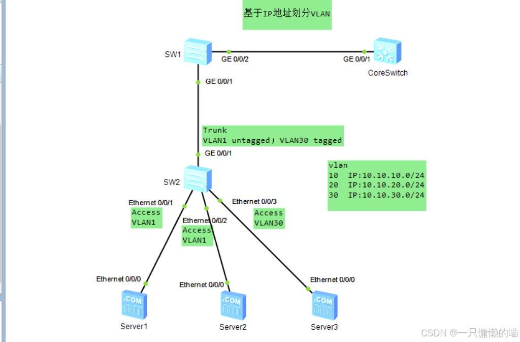
一、拓扑图如下
二、配置步骤如下
- 根据拓扑图配置设备基本信息;
- 在SW2创建VLAN30,把Ethernet0/0/1、Ethernet0/0/2接口配置为Access类型,并加入VLAN1,把Ethernet0/0/3接口配置为Access类型,并加入VLAN30;
- 将SW2的GigabitEthernet0/0/1接口配置为Trunk类型,并在允许通过的VLAN-ID列表中添加VLAN1及VLAN30;
- 在SW1创建VLAN10、20、30,并配置IP网段10.10.10.0/24与VLAN10的对应关系,配置IP网段10.10.20.0/24与VLAN20的对应关系;
- 将SW1的GigabitEthernet0/0/1接口配置为Hybrid类型,并在untagged列表添加VLAN10、20,在tagged列表添加VLAN30,同时配置使能基于IP地址划分VLAN;
- 将SW1的GigabitEthernet0/0/2接口配置为Trunk类型,并在允许通过的VLAN-ID列表中添加VLAN10、20、30;
三、代码详解
1. 基础配置
- 设备重命名:
sysname SW2 (SW2即是重命名后的设备名称) - 关闭日志:
undo info-center enable(实验常用,生产环境慎用,关闭后将无法查看系统日志)
2. VLAN配置
- 创建VLAN:
vlan batch 10 20 30//该命令可创建多个vlan - 接口划分:
- E0/0/1:设为Access类型,
- interface Ethernet0/0/1 //进入接口
- port link-type access //配置其为access类型
3. Trunk口配置
- G0/0/1设为Trunk:
port link-type trunk - 允许的VLAN:port trunk allow-pass vlan 1 30 //允许vlan1和vlan30通过
四、ensp各设备代码如下
SW1
system-view
sysname sw1
undo info-center enable
vlan batch 10 20 30
interface GigabitEthernet0/0/1
port hybrid tagged vlan 30
port hybrid untagged vlan 10 20
interface GigabitEthernet0/0/2
port link-type trunk
port trunk allow-pass vlan 10 20 30
interface Vlanif10
ip address 10.10.10.1 255.255.255.0
interface Vlanif20
ip address 10.10.20.1 255.255.255.0
CoreSwitch
system-view
sysname CoreSwitch
undo info-center enable
SW2
system-view
sysname sw2
undo info-center enable
vlan batch 30
interface Ethernet0/0/1
port link-type access
interface Ethernet0/0/2
port link-type access
interface Ethernet0/0/3
port link-type access
port default vlan 30
interface GigabitEthernet0/0/1
port link-type trunk
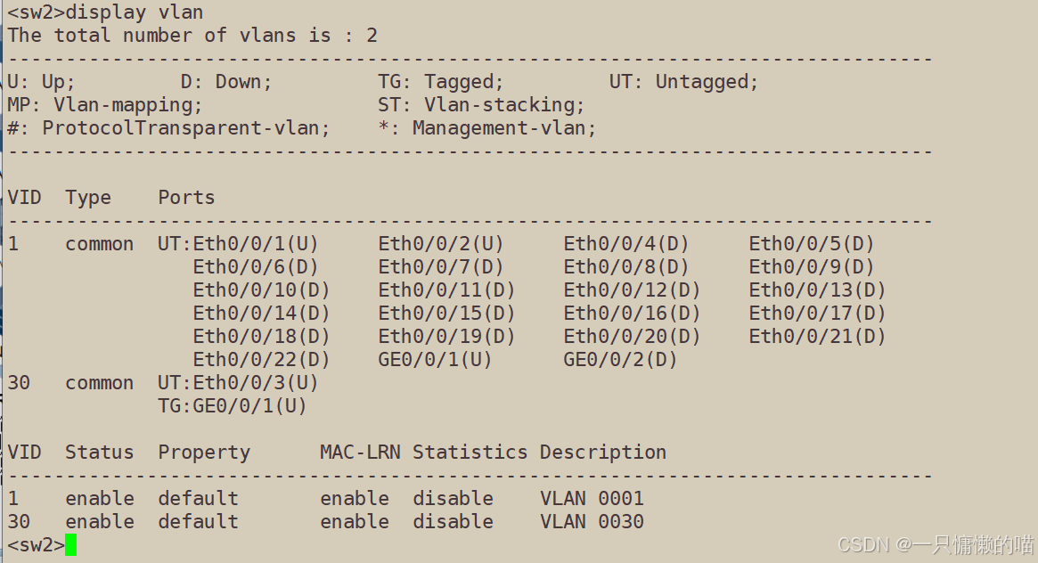
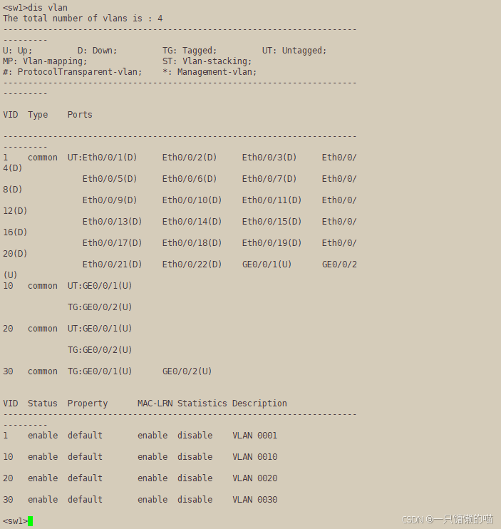
port trunk allow-pass vlan 30五、验证结果如下
可以看到vlan的信息,确认vlan和接口信息正确,实验完成


 9108
9108

 被折叠的 条评论
为什么被折叠?
被折叠的 条评论
为什么被折叠?
 到【灌水乐园】发言


