


eNSP实验——动态路由OSPF(单区域+多区域)
仅供参考
基础概念
OSPF协议简介
OSPF 简介
- OSPF(Open Shortest Path First) 是一种链路状态路由协议,用于在 IP 网络中动态计算路由。
- 它基于 Dijkstra 的最短路径优先(SPF)算法,通过构建链路状态数据库(LSDB)来计算最短路径。
1. OSPF 的特点
- 分层设计:支持多区域(Area),其中 Area 0 是骨干区域,其他区域必须与 Area 0 直接相连。
- 链路状态协议:路由器通过交换链路状态通告(LSA)来同步网络拓扑信息。
- 快速收敛:当网络拓扑发生变化时,OSPF 能够快速重新计算路由。
- 支持 VLSM 和 CIDR:适用于复杂的网络环境。
2. OSPF 报文类型
OSPF 使用以下 5 种报文类型来交换信息:
| 报文类型 | 描述 |
|---|---|
| Hello 报文 | 用于发现和维护邻居关系,定期发送(默认 10 秒)。 |
| DBD(Database Description)报文 | 用于描述链路状态数据库(LSDB)的摘要信息,用于初始同步。 |
| LSR(Link State Request)报文 | 用于请求特定的链路状态记录(LSA)。 |
| LSU(Link State Update)报文 | 用于发送链路状态记录(LSA),更新邻居的 LSDB。 |
| LSAck(Link State Acknowledgment)报文 | 用于确认接收到的 LSU 报文。 |
3. OSPF 的工作过程
- 邻居发现:通过 Hello 报文发现邻居路由器。
- 链路状态数据库同步:通过 DBD、LSR 和 LSU 报文同步 LSDB。
- 路由计算:使用 SPF 算法计算最短路径树(Shortest Path Tree)。
- 路由表更新:将计算出的路由添加到路由表中。
4. OSPF 区域类型
- 骨干区域(Area 0):所有其他区域必须与 Area 0 直接相连。
- 普通区域:非骨干区域,用于连接终端网络。
- Stub 区域:不允许外部路由进入,减少 LSDB 大小。
- NSSA(Not-So-Stubby Area):允许引入外部路由,但限制其传播。
5. OSPF 的核心功能
| 功能 | 通俗解释 | 技术术语 |
|---|---|---|
| 快速收敛 | 网络一有变化(如断线),所有路由器秒级更新“地图” | 链路状态算法、Dijkstra算法 |
| 支持大规模网络 | 把网络分成多个“小区”(区域),每个小区独立管理,降低复杂度 | 区域划分(Area 0为核心骨干区域) |
| 智能选路 | 优先选“高速公路”(高带宽链路),避开“乡间小道”(低带宽路径) | 基于带宽的Cost值计算 |
| 路由策略灵活 | 可设置“VIP通道”(路由过滤/汇总),让关键业务走专属路径 | LSA泛洪、路由汇总 |
注释:
- 收敛速度:网络拓扑变化后,所有路由器同步信息的速度。OSPF能做到秒级更新,而老旧协议(如RIP)可能需要几分钟。
- 区域划分:类似城市分“行政区”,每个区独立管理,再通过核心区(Area 0)互联,避免全网路由器都背下整张地图。
如何理解 OSPF 的“区域”和“进程号
-
区域(Area):
-
作用:把网络分成多个“微信群”,每个群内共享局部地图,再通过“群主”(Area 0)汇总信息。
-
示例:
一家电商公司分“华北区”和“华南区”,各自管理本地仓库路由,再通过总部(Area 0)互联。
-
-
进程号(Process ID):
-
作用:同一台路由器可开多个“独立任务”,比如一个管办公网,一个管监控网,互不干扰。
-
示例:
公司路由器同时运行OSPF进程100(内网)和200(VPN专线),数据完全隔离。
-
OSPF 优缺点对比
| 特性 | OSPF优点 | OSPF缺点 |
|---|---|---|
| 收敛速度 | 响应快(网络变化秒级更新) | 配置复杂(需规划区域和链路成本) |
| 网络规模 | 支持大规模网络 | 资源消耗高(CPU/内存占用较大) |
| 路径选择 | 智能选路(优先选择高带宽链路) | 依赖网络稳定性(频繁拓扑变化影响性能) |
| 路由策略 | 高度灵活(支持路由过滤、汇总等) | - |
| 路由更新 | 仅发送变化信息(节省带宽) | - |
注释:
- 收敛速度:指网络拓扑变化后,所有路由器更新路由表的速度。
- 路由策略:如根据业务需求优先选择特定路径。
区域(Area)与进程号(Process-ID)的区别
| 维度 | 区域(Area) | 进程号(Process-ID) |
|---|---|---|
| 作用范围 | 全网统一规划(不同区域需互联) | 仅本地生效(不同进程互不影响) |
| 标识符意义 | 全局唯一标识(通过报文传递) | 本地标识(不传递到其他设备) |
| 核心目标 | 优化管理(减少路由信息泛洪) | 隔离策略(如区分内外网路由) |
| 典型应用 | 分层设计(如骨干区域 Area 0) | 多实例共存(同时管理多个网络) |
注释:
- 区域:类似于“分区域管理”,骨干区域(Area 0)必须存在。
- 进程号:类似“多任务模式”,同一设备可运行多个独立 OSPF 实例。
OSPF 和 RIP 对比
| 协议 | 适用网络规模 | 核心限制 | 典型应用场景 |
|---|---|---|---|
| RIP | 小型网络(≤15跳) | 最大跳数限制(15 跳)、易产生路由环路 | 老旧设备、简单局域网 |
| OSPF | 中大型网络 | 配置复杂(需区域规划、链路成本计算) | 企业网络、数据中心、ISP |
注释:
- RIP 跳数限制:超过 15 跳的路由会被丢弃,因此仅适合小型网络。
- OSPF 配置复杂:需规划区域、链路成本(Cost)等,但灵活性更高。
三种路由的区别
| 特点/类型 | 静态路由 | 动态路由 | 默认路由 |
|---|---|---|---|
| 配置方式 | 手动配置 | 自动学习(如OSPF、RIP) | 手动配置(通常一条通用规则) |
| 路由更新 | 不自动更新 | 自动更新(实时适应网络变化) | 不更新(固定指向预设出口) |
| 应用场景 | 小型网络、简单拓扑 | 大型网络、复杂拓扑(如企业网) | 网络出口、简化路由表(如互联网网关) |
| 优点 | 简单、稳定、无额外资源消耗 | 灵活、自动适应、支持动态拓扑变化 | 配置极简、减少冗余路由条目 |
| 缺点 | 不灵活、配置复杂 | 配置复杂、占用CPU/内存资源 | 灵活性差(可能引发“路由黑洞”) |
| 优先级 | 最高(优先匹配) | 中等(根据协议优先级) | 最低(仅作“最后选项”) |
注释:
- 路由黑洞:当默认路由指向的出口无法处理某些流量时,数据包会被丢弃(类似“黑洞”)。
- 优先级:路由器按优先级匹配路由,静态路由因精确性高而优先。
三种路由的通俗解释
- 静态路由 适合简单、稳定的网络环境,配置简单但缺乏灵活性。
- 动态路由 适合大型、复杂的网络环境,能够自动适应网络变化,但配置和管理复杂。
- 默认路由 是一种特殊的路由,用于简化路由表,将未知流量转发到指定下一跳网关或出口接口。
1. 静态路由:固定路线,手动导航
-
特点:
- 手动配置:像在纸上画地图一样,管理员需要一条一条指定路径。
- 不自动更新:如果某条路断了,必须手动修改路线。
-
适用场景:
家庭网络、小型办公室(比如把“内网流量”指向打印机,“外网流量”指向路由器)。
-
优缺点:
- ✅ 优点:简单稳定,不占用额外资源。
- ❌ 缺点:维护麻烦,网络一变就得重新画地图。
类比:
像固定公交线路——路线固定不变,但遇到修路就得停运,直到司机改道。
2. 动态路由:智能导航,自动绕路
-
特点:
- 自动学习:路由器之间“聊天”(如OSPF、RIP协议),实时交换路况信息。
- 自动调整:如果某条路堵了,会立刻找新路线,无需人工干预。
-
适用场景:
企业总部与多个分公司的网络互联,或大型数据中心内部通信。
-
优缺点:
- ✅ 优点:灵活高效,能应对复杂网络变化。
- ❌ 缺点:需要更多“脑力”(CPU/内存资源),配置复杂。
类比:
像实时导航的GPS——堵车时自动绕路,但需要手机一直开着导航(耗电)。
3. 默认路由:万能备用出口
-
特点:
- 兜底规则:所有“不知道去哪”的流量,统一丢给指定出口(如外网网关)。
- 极简配置:通常只需一条规则,大幅减少路由表条目。
-
适用场景:
公司出口路由器,把所有外网流量指向ISP(比如互联网网关)。
-
优缺点:
- ✅ 优点:配置简单,路由表清爽。
- ❌ 缺点:如果出口配置错误,流量可能掉进“黑洞”(直接被丢弃)。
类比:
像商场应急出口——平时不用,但所有找不到路的人都从这里出去。不过如果应急出口锁了,人就卡在里面。
一句话总结
- 静态路由:“自己画地图,路断了自己改。”
- 动态路由:“路由器自动组队聊天,堵车就绕路。”
- 默认路由:“不知道去哪?全走这个出口!”
OSPF 单区域配置
实验环境
备注:前面从单区域开始,后面是多区域(两个是分开的)
拓扑图
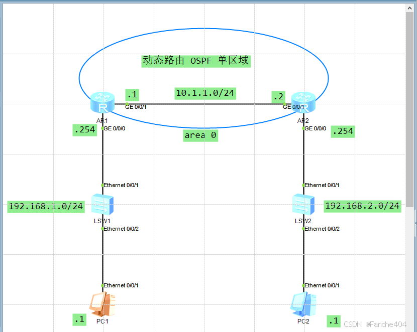
设备信息划分
| 设备名称 | Router ID(路由ID) | Process ID(进程ID) | 接口 | IP地址/子网 | 区域 |
|---|---|---|---|---|---|
| AR1 | 1.1.1.1 | 1 | GE 0/0/1 | 10.1.1.1/24 | Area 0 |
| GE 0/0/0 | 192.168.1.254/24 | Area 0 | |||
| AR2 | 2.2.2.2 | 1 | GE 0/0/1 | 10.1.1.2/24 | Area 0 |
| GE 0/0/0 | 192.168.2.254/24 | Area 0 | |||
| LSW1(SW1) | N/A | N/A | Ethernet 0/0/1 | N/A(二层交换机) | N/A |
| Ethernet 0/0/2 | N/A(连接 PC1) | N/A | |||
| LSW2(SW2) | N/A | N/A | Ethernet 0/0/1 | N/A(二层交换机) | N/A |
| Ethernet 0/0/2 | N/A(连接 PC2) | N/A | |||
| PC1 | N/A | N/A | NIC | 192.168.1.1/24 | N/A |
| PC2 | N/A | N/A | NIC | 192.168.2.1/24 | N/A |
配置接口IP地址
先给两个路由设备的接口地址配置IP地址
AR1配置接口IP地址
[AR1]int g0/0/1
[AR1-GigabitEthernet0/0/1]ip address 10.1.1.1 24
[AR1-GigabitEthernet0/0/1]q
[AR1]
[AR1]
[AR1]int g0/0/0
[AR1-GigabitEthernet0/0/0]ip address 192.168.1.254 24
[AR1-GigabitEthernet0/0/0]q
[AR1]
[AR1]dis ip int b
*down: administratively down
^down: standby
(l): loopback
(s): spoofing
The number of interface that is UP in Physical is 3
The number of interface that is DOWN in Physical is 1
The number of interface that is UP in Protocol is 3
The number of interface that is DOWN in Protocol is 1

Interface                         IP Address/Mask      Physical   Protocol
GigabitEthernet0/0/0              192.168.1.254/24     up         up
GigabitEthernet0/0/1              10.1.1.1/24          up         up
GigabitEthernet0/0/2              unassigned           down       down
NULL0                             unassigned           up         up(s)
[AR1]
AR2配置接口IP地址
[AR2]int g0/0/1
[AR2-GigabitEthernet0/0/1]ip address 10.1.1.2 24
[AR2-GigabitEthernet0/0/1]q
[AR2]
[AR2]int g0/0/0
[AR2-GigabitEthernet0/0/0]ip address 192.168.2.254 24
[AR2-GigabitEthernet0/0/0]q
[AR2]
[AR2]dis ip int b
*down: administratively down
^down: standby
(l): loopback
(s): spoofing
The number of interface that is UP in Physical is 3
The number of interface that is DOWN in Physical is 1
The number of interface that is UP in Protocol is 3
The number of interface that is DOWN in Protocol is 1

Interface                         IP Address/Mask      Physical   Protocol
GigabitEthernet0/0/0              192.168.2.254/24     up         up
GigabitEthernet0/0/1              10.1.1.2/24          up         up
GigabitEthernet0/0/2              unassigned           down       down
NULL0                             unassigned           up         up(s)
[AR2]
配置完接口IP地址之后,是可以实现直连网段的通信;现在PC1还不能跨网段和PC2进行这一个通信
配置OSPF区域
备注:做的是单区域的OSPF,这里两台路由器直连之间就是area 0区域
Process ID:用于区分设备上的不同 OSPF 进程,必须唯一。
Router ID:用于唯一标识 OSPF 路由器,建议手动配置以确保稳定性。(自动选择的优先级:手动配置 > 环回接口 IP > 物理接口 IP)。
# 宣告网络
network [目标网络] [目标网络反掩码]
AR1配置 OSPF 路由通告AR2
AR1 直连 192.168.1.0/24 和 10.1.1.0/24 这两个网段,通过 network 命令将这两个网段宣告到 OSPF 区域 0 中。
[AR1]router id 1.1.1.1		# 设置路由器的 Router ID 为 1.1.1.1
Info: Router ID has been modified, please reset the relative protocols manually
to update the Router ID.
[AR1]ospf 1			# 进入 OSPF 进程 1 的配置模式
[AR1-ospf-1]area 0		# 进入 OSPF 区域 0 的配置模式(骨干区域)
[AR1-ospf-1-area-0.0.0.0]network 192.168.1.0 0.0.0.255		# 将子网 192.168.1.0/24 宣告到 OSPF 区域 0 中
[AR1-ospf-1-area-0.0.0.0]network 10.1.1.0 0.0.0.255		# 反掩码 0.0.0.255 表示前 24 位为网络位,后 8 位为主机位
[AR1-ospf-1-area-0.0.0.0]dis th		# 显示当前配置(display this 的缩写)
[V200R003C00]
#
 area 0.0.0.0
  network 10.1.1.0 0.0.0.255
  network 192.168.1.0 0.0.0.255
#
# 以上是当前 OSPF 进程 1 的配置内容,包括区域 0 和宣告的两个子网
return
[AR1-ospf-1-area-0.0.0.0]
AR2配置 OSPF 路由通告AR1
AR1 直连 192.168.2.0/24 和 10.1.1.0/24 这两个网段,通过 network 命令将这两个网段宣告到 OSPF 区域 0 中。
[AR2]router id 2.2.2.2		# 设置路由器的 Router ID 为 2.2.2.2
Info: Router ID has been modified, please reset the relative protocols manually
to update the Router ID.
[AR2]ospf 1			# 进入 OSPF 进程 1 的配置模式
[AR2-ospf-1]area 0		# 进入 OSPF 区域 0 的配置模式(骨干区域)
[AR2-ospf-1-area-0.0.0.0]network 192.168.2.0 0.0.0.255		# 将子网 192.168.2.0/24 宣告到 OSPF 区域 0 中
[AR2-ospf-1-area-0.0.0.0]network 10.1.1.0 0.0.0.255		# 反掩码 0.0.0.255 表示前 24 位为网络位,后 8 位为主机位
[AR2-ospf-1-area-0.0.0.0]dis th		# 显示当前配置(display this 的缩写)
[V200R003C00]
#
 area 0.0.0.0
  network 10.1.1.0 0.0.0.255
  network 192.168.2.0 0.0.0.255
#
# 以上是当前 OSPF 进程 1 的配置内容,包括区域 0 和宣告的两个子网
return
[AR2-ospf-1-area-0.0.0.0]
查看路由表
在 AR1 和 AR2 上分别执行以下命令,检查 OSPF 路由是否学习到:
[AR1]dis ip routing-table
Route Flags: R - relay, D - download to fib
------------------------------------------------------------------------------
Routing Tables: Public
         Destinations : 11       Routes : 11

Destination/Mask    Proto   Pre  Cost      Flags NextHop         Interface

       10.1.1.0/24  Direct  0    0           D   10.1.1.1        GigabitEthernet 0/0/1
       10.1.1.1/32  Direct  0    0           D   127.0.0.1       GigabitEthernet 0/0/1
     10.1.1.255/32  Direct  0    0           D   127.0.0.1       GigabitEthernet 0/0/1
      127.0.0.0/8   Direct  0    0           D   127.0.0.1       InLoopBack0
      127.0.0.1/32  Direct  0    0           D   127.0.0.1       InLoopBack0
127.255.255.255/32  Direct  0    0           D   127.0.0.1       InLoopBack0
    192.168.1.0/24  Direct  0    0           D   192.168.1.254   GigabitEthernet 0/0/0
  192.168.1.254/32  Direct  0    0           D   127.0.0.1       GigabitEthernet 0/0/0
  192.168.1.255/32  Direct  0    0           D   127.0.0.1       GigabitEthernet 0/0/0
    192.168.2.0/24  OSPF    10   2           D   10.1.1.2        GigabitEthernet 0/0/1	# 这里已经和192.168.1.0网段同步
255.255.255.255/32  Direct  0    0           D   127.0.0.1       InLoopBack0

[AR1]
[AR2]dis ip routing-table
Route Flags: R - relay, D - download to fib
------------------------------------------------------------------------------
Routing Tables: Public
         Destinations : 11       Routes : 11

Destination/Mask    Proto   Pre  Cost      Flags NextHop         Interface

       10.1.1.0/24  Direct  0    0           D   10.1.1.2        GigabitEthernet 0/0/1
       10.1.1.2/32  Direct  0    0           D   127.0.0.1       GigabitEthernet 0/0/1
     10.1.1.255/32  Direct  0    0           D   127.0.0.1       GigabitEthernet 0/0/1
      127.0.0.0/8   Direct  0    0           D   127.0.0.1       InLoopBack0
      127.0.0.1/32  Direct  0    0           D   127.0.0.1       InLoopBack0
127.255.255.255/32  Direct  0    0           D   127.0.0.1       InLoopBack0
    192.168.1.0/24  OSPF    10   2           D   10.1.1.1        GigabitEthernet 0/0/1	# 这里已经和192.168.1.0网段同步
    192.168.2.0/24  Direct  0    0           D   192.168.2.254   GigabitEthernet 0/0/0
  192.168.2.254/32  Direct  0    0           D   127.0.0.1       GigabitEthernet 0/0/0
  192.168.2.255/32  Direct  0    0           D   127.0.0.1       GigabitEthernet 0/0/0
255.255.255.255/32  Direct  0    0           D   127.0.0.1       InLoopBack0

[AR2]
[AR2]ping 192.168.1.1		# 从AR2路由能够和PC1通信,那PC2也是能够和PC2进行一个通信
  PING 192.168.1.1: 56  data bytes, press CTRL_C to break
    Request time out
    Reply from 192.168.1.1: bytes=56 Sequence=2 ttl=127 time=50 ms
    Reply from 192.168.1.1: bytes=56 Sequence=3 ttl=127 time=50 ms
    Reply from 192.168.1.1: bytes=56 Sequence=4 ttl=127 time=60 ms
    Reply from 192.168.1.1: bytes=56 Sequence=5 ttl=127 time=70 ms

  --- 192.168.1.1 ping statistics ---
    5 packet(s) transmitted
    4 packet(s) received
    20.00% packet loss
    round-trip min/avg/max = 50/57/70 ms

[AR2]
AR1 的路由表中应有 192.168.2.0/24 网段(来自 AR2)。
AR2 的路由表中应有 192.168.1.0/24 网段(来自 AR1)。
检查OSPF的邻居状态
[AR1]display ospf peer

	 OSPF Process 1 with Router ID 10.1.1.1
		 Neighbors

 Area 0.0.0.0 interface 10.1.1.1(GigabitEthernet0/0/1)'s neighbors
 Router ID: 2.2.2.2          Address: 10.1.1.2        # 这是邻居路由器(AR2)的 Router ID,表示 AR1 已经成功识别到 AR2。
   State: Full  Mode:Nbr is  Slave  Priority: 1		# state(状态):Full
   DR: 10.1.1.1  BDR: 10.1.1.2  MTU: 0
   Dead timer due in 33  sec
   Retrans timer interval: 5
   Neighbor is up for 00:10:31
   Authentication Sequence: [ 0 ]

[AR1]
- 成功标志:
- OSPF 邻居状态为 Full。
- OSPF 路由表中能看到宣告的网段。
- 全局路由表中能看到 OSPF 路由。
能看到 AR1 宣告的网段(如 192.168.1.0/24 和 10.1.1.0/24)以及从 AR2 学习到的其他网段。
[AR1]dis ospf routing

	 OSPF Process 1 with Router ID 10.1.1.1
		  Routing Tables

 Routing for Network
 Destination        Cost  Type       NextHop         AdvRouter       Area
 10.1.1.0/24        1     Transit    10.1.1.1        10.1.1.1        0.0.0.0
 192.168.1.0/24     1     Stub       192.168.1.254   10.1.1.1        0.0.0.0
 192.168.2.0/24     2     Stub       10.1.1.2        2.2.2.2         0.0.0.0

 Total Nets: 3
 Intra Area: 3  Inter Area: 0  ASE: 0  NSSA: 0

[AR1]
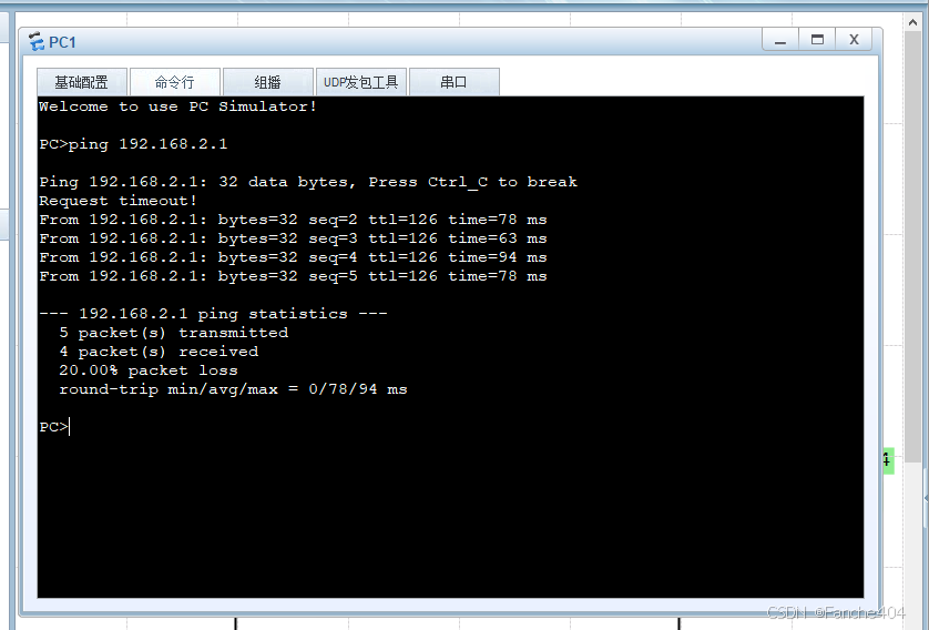
测试
OSPF 多区域配置
- 确保路由器 ID 唯一,避免冲突。
- 正确划分区域,确保所有非骨干区域连接到 Area 0。
- 检查 OSPF 区域配置,确保一致。
- 确保 OSPF 邻居关系建立成功,状态为 Full。
- 检查路由表,确保 OSPF 路由被正确学习。
- 验证通信,使用
ping命令测试连通性。
实验环境
拓扑图
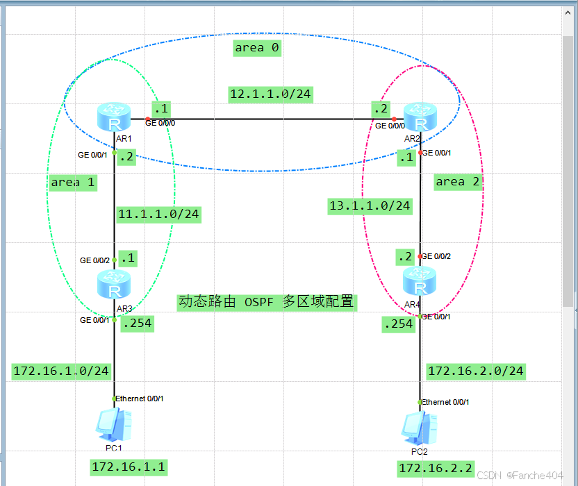
设备信息划分
| 设备 | 接口 | IP地址 | 区域 |
|---|---|---|---|
| AR1 | GE 0/0/0 | 12.1.1.1/24 | Area 0 |
| GE 0/0/1 | 11.1.1.1/24 | Area 1 | |
| AR2 | GE 0/0/0 | 12.1.1.2/24 | Area 0 |
| GE 0/0/1 | 13.1.1.1/24 | Area 2 | |
| AR3 | GE 0/0/1 | 11.1.1.254/24 | Area 1 |
| Ethernet 0/0/1 | 172.16.1.1/24 | N/A | |
| AR4 | GE 0/0/1 | 13.1.1.254/24 | Area 2 |
| Ethernet 0/0/1 | 172.16.2.2/24 | N/A | |
| PC1 | Ethernet 0/0/1 | 172.16.1.1/24 | N/A |
| PC2 | Ethernet 0/0/1 | 172.16.2.2/24 | N/A |
配置接口IP地址
[R1]int g0/0/0
[R1-GigabitEthernet0/0/0]ip address 12.1.1.1 24
[R1-GigabitEthernet0/0/0]q
[R1]
[R1]int g0/0/1
[R1-GigabitEthernet0/0/1]ip address 11.1.1.2 24
[R1-GigabitEthernet0/0/1]q
[R1]
[R1]dis ip int b
*down: administratively down
^down: standby
(l): loopback
(s): spoofing
The number of interface that is UP in Physical is 3
The number of interface that is DOWN in Physical is 1
The number of interface that is UP in Protocol is 3
The number of interface that is DOWN in Protocol is 1

Interface                         IP Address/Mask      Physical   Protocol
GigabitEthernet0/0/0              12.1.1.1/24          up         up
GigabitEthernet0/0/1              11.1.1.2/24          up         up
GigabitEthernet0/0/2              unassigned           down       down
NULL0                             unassigned           up         up(s)
[R1]
[R2]int g0/0/0
[R2-GigabitEthernet0/0/0]ip address 12.1.1.2 24
[R2-GigabitEthernet0/0/0]q
[R2]
[R2]int g0/0/1
[R2-GigabitEthernet0/0/1]ip address 13.1.1.1 24
[R2-GigabitEthernet0/0/1]q
[R2]dis ip int b
*down: administratively down
^down: standby
(l): loopback
(s): spoofing
The number of interface that is UP in Physical is 3
The number of interface that is DOWN in Physical is 1
The number of interface that is UP in Protocol is 3
The number of interface that is DOWN in Protocol is 1

Interface                         IP Address/Mask      Physical   Protocol
GigabitEthernet0/0/0              12.1.1.2/24          up         up
GigabitEthernet0/0/1              13.1.1.1/24          up         up
GigabitEthernet0/0/2              unassigned           down       down
NULL0                             unassigned           up         up(s)
[R2]
[R3]int g0/0/1
[R3-GigabitEthernet0/0/1]ip address 172.16.1.254 24
[R3-GigabitEthernet0/0/1]q
[R3]
[R3]int g0/0/2
[R3-GigabitEthernet0/0/2]ip address 11.1.1.1 24
[R3-GigabitEthernet0/0/2]q
[R3]dis ip int b
*down: administratively down
^down: standby
(l): loopback
(s): spoofing
The number of interface that is UP in Physical is 3
The number of interface that is DOWN in Physical is 1
The number of interface that is UP in Protocol is 3
The number of interface that is DOWN in Protocol is 1

Interface                         IP Address/Mask      Physical   Protocol
GigabitEthernet0/0/0              unassigned           down       down
GigabitEthernet0/0/1              172.16.1.254/24      up         up
GigabitEthernet0/0/2              11.1.1.1/24          up         up
NULL0                             unassigned           up         up(s)
[R3]
[R4]int g0/0/1
[R4-GigabitEthernet0/0/1]ip address 172.16.2.254 24
[R4-GigabitEthernet0/0/1]q
[R4]
[R4]int g0/0/2
[R4-GigabitEthernet0/0/2]ip address 13.1.1.2 24
[R4-GigabitEthernet0/0/2]q
[R4]dis ip int b
*down: administratively down
^down: standby
(l): loopback
(s): spoofing
The number of interface that is UP in Physical is 3
The number of interface that is DOWN in Physical is 1
The number of interface that is UP in Protocol is 3
The number of interface that is DOWN in Protocol is 1

Interface                         IP Address/Mask      Physical   Protocol
GigabitEthernet0/0/0              unassigned           down       down
GigabitEthernet0/0/1              172.16.2.254/24      up         up
GigabitEthernet0/0/2              13.1.1.2/24          up         up
NULL0                             unassigned           up         up(s)
[R4]
OSPF通告各个网段
为什么需要配置 network 172.16.1.0 和 network 172.16.2.0?
- PC1 和 PC2 的子网:
172.16.1.0/24和172.16.2.0/24是 PC1 和 PC2 所在的子网。如果这些子网没有通过 OSPF 通告到网络中,其他路由器(如 AR1、AR2)将无法学习到这些子网的路由信息。 - 路由可达性:如果没有配置
network 172.16.1.0和network 172.16.2.0,OSPF 不会将这些子网的路由信息传播到其他区域,导致 PC1 和 PC2 无法与其他设备通信
R3和R4需要通告PC所处的网段,否则R1和R2无法学习到R3和R4的子网路由信息。
[R1]router id 1.1.1.1
Info: Router ID has been modified, please reset the relative protocols manually
to update the Router ID.
[R1]ospf 1
[R1-ospf-1]area 0
[R1-ospf-1-area-0.0.0.0]network 12.1.1.0 0.0.0.255
[R1-ospf-1-area-0.0.0.0]q
[R1-ospf-1]area 1
[R1-ospf-1-area-0.0.0.1]network 11.1.1.0 0.0.0.255
[R1-ospf-1-area-0.0.0.1]q
[R1-ospf-1]dis th
[V200R003C00]
#
ospf 1
 area 0.0.0.0
  network 12.1.1.0 0.0.0.255
 area 0.0.0.1
  network 11.1.1.0 0.0.0.255
#
return
[R1-ospf-1]
[R2]router id 2.2.2.2
Info: Router ID has been modified, please reset the relative protocols manually
to update the Router ID.
[R2]ospf 1
[R2-ospf-1]area 0
[R2-ospf-1-area-0.0.0.0]network 12.1.1.0 0.0.0.255
[R2-ospf-1-area-0.0.0.0]q
[R2-ospf-1]area 2
[R2-ospf-1-area-0.0.0.2]network 13.1.1.0 0.0.0.255
[R2-ospf-1-area-0.0.0.2]q
[R2-ospf-1]dis th
[V200R003C00]
#
ospf 1
 area 0.0.0.0
  network 12.1.1.0 0.0.0.255
 area 0.0.0.2
  network 13.1.1.0 0.0.0.255
#
return
[R2-ospf-1]
在 AR3 和 AR4 上,把 172.16.1.0/24 和 172.16.2.0/24 子网通告到 OSPF 中
[R3]router id 3.3.3.3
Info: Router ID has been modified, please reset the relative protocols manually
to update the Router ID.
[R3]ospf 1
[R3-ospf-1]area 1
[R3-ospf-1-area-0.0.0.1]network 11.1.1.0 0.0.0.255
[R3-ospf-1-area-0.0.0.1]network 172.16.1.0 0.0.0.255	# PC1所处的子网
[R3-ospf-1-area-0.0.0.1]q
[R3-ospf-1]
[R3-ospf-1]dis th
[V200R003C00]
#
ospf 1
 area 0.0.0.1
  network 11.1.1.0 0.0.0.255
  network 172.16.1.0 0.0.0.255
#
return
[R3-ospf-1]
[R4]router id 4.4.4.4
Info: Router ID has been modified, please reset the relative protocols manually
to update the Router ID.
[R4]
[R4]ospf 1
[R4-ospf-1]area 2
[R4-ospf-1-area-0.0.0.2]network 13.1.1.0 0.0.0.255
[R4-ospf-1-area-0.0.0.2]network 172.16.2.0 0.0.0.255	# PC2所处的子网
[R4-ospf-1-area-0.0.0.2]q
[R4-ospf-1]
[R4-ospf-1]dis th
[V200R003C00]
#
ospf 1
 area 0.0.0.2
  network 13.1.1.0 0.0.0.255
  network 172.16.2.0 0.0.0.255
#
return
[R4-ospf-1]
查看路由表和OSPF邻居状态
查看路由表
这里拿R1和R2来看,有三条网段的OSPF通告网段的子网路由信息
[R1]dis ip routing-table
Route Flags: R - relay, D - download to fib
------------------------------------------------------------------------------
Routing Tables: Public
         Destinations : 13       Routes : 13

Destination/Mask    Proto   Pre  Cost      Flags NextHop         Interface

       11.1.1.0/24  Direct  0    0           D   11.1.1.2        GigabitEthernet 0/0/1
       11.1.1.2/32  Direct  0    0           D   127.0.0.1       GigabitEthernet 0/0/1
     11.1.1.255/32  Direct  0    0           D   127.0.0.1       GigabitEthernet 0/0/1
       12.1.1.0/24  Direct  0    0           D   12.1.1.1        GigabitEthernet 0/0/0
       12.1.1.1/32  Direct  0    0           D   127.0.0.1       GigabitEthernet 0/0/0
     12.1.1.255/32  Direct  0    0           D   127.0.0.1       GigabitEthernet 0/0/0
       13.1.1.0/24  OSPF    10   2           D   12.1.1.2        GigabitEthernet 0/0/0
      127.0.0.0/8   Direct  0    0           D   127.0.0.1       InLoopBack0
      127.0.0.1/32  Direct  0    0           D   127.0.0.1       InLoopBack0
127.255.255.255/32  Direct  0    0           D   127.0.0.1       InLoopBack0
     172.16.1.0/24  OSPF    10   2           D   11.1.1.1        GigabitEthernet0/0/1
     172.16.2.0/24  OSPF    10   3           D   12.1.1.2        GigabitEthernet0/0/0
255.255.255.255/32  Direct  0    0           D   127.0.0.1       InLoopBack0

[R1]
[R2]dis ip routing-table
Route Flags: R - relay, D - download to fib
------------------------------------------------------------------------------
Routing Tables: Public
         Destinations : 13       Routes : 13

Destination/Mask    Proto   Pre  Cost      Flags NextHop         Interface

       11.1.1.0/24  OSPF    10   2           D   12.1.1.1        GigabitEthernet 0/0/0
       12.1.1.0/24  Direct  0    0           D   12.1.1.2        GigabitEthernet 0/0/0
       12.1.1.2/32  Direct  0    0           D   127.0.0.1       GigabitEthernet 0/0/0
     12.1.1.255/32  Direct  0    0           D   127.0.0.1       GigabitEthernet 0/0/0
       13.1.1.0/24  Direct  0    0           D   13.1.1.1        GigabitEthernet 0/0/1
       13.1.1.1/32  Direct  0    0           D   127.0.0.1       GigabitEthernet 0/0/1
     13.1.1.255/32  Direct  0    0           D   127.0.0.1       GigabitEthernet 0/0/1
      127.0.0.0/8   Direct  0    0           D   127.0.0.1       InLoopBack0
      127.0.0.1/32  Direct  0    0           D   127.0.0.1       InLoopBack0
127.255.255.255/32  Direct  0    0           D   127.0.0.1       InLoopBack0
     172.16.1.0/24  OSPF    10   3           D   12.1.1.1        GigabitEthernet 0/0/0
     172.16.2.0/24  OSPF    10   2           D   13.1.1.2        GigabitEthernet 0/0/1
255.255.255.255/32  Direct  0    0           D   127.0.0.1       InLoopBack0

[R2]
查看OSPF邻居状态
查看R1的OSPF邻居状态,这里可以看到和R2和R3邻居关系建立成功。
R1 没有直接与 R4 建立邻居关系,是因为 R1 和 R4 不是直连的邻居,而是通过其他路由器间接连接。
因此,R1 不会直接与 R4 建立 OSPF 邻居关系。
R1 与 R2 和 R3 的 OSPF 邻居关系已成功建立,状态为 Full,表示路由信息已完全同步。
[R1]dis ospf peer

	 OSPF Process 1 with Router ID 1.1.1.1
		 Neighbors

 Area 0.0.0.0 interface 12.1.1.1(GigabitEthernet0/0/0)'s neighbors
 Router ID: 2.2.2.2          Address: 12.1.1.2
   State: Full  Mode:Nbr is  Master  Priority: 1
   DR: 12.1.1.1  BDR: 12.1.1.2  MTU: 0
   Dead timer due in 36  sec
   Retrans timer interval: 5
   Neighbor is up for 00:20:01
   Authentication Sequence: [ 0 ]

		 Neighbors

 Area 0.0.0.1 interface 11.1.1.2(GigabitEthernet0/0/1)'s neighbors
 Router ID: 3.3.3.3          Address: 11.1.1.1
   State: Full  Mode:Nbr is  Master  Priority: 1
   DR: 11.1.1.2  BDR: 11.1.1.1  MTU: 0
   Dead timer due in 32  sec
   Retrans timer interval: 5
   Neighbor is up for 00:12:08
   Authentication Sequence: [ 0 ]

[R1]
R2 与 R4 的 OSPF 邻居关系也已成功建立,状态为 Full。
[R2]dis ospf peer

	 OSPF Process 1 with Router ID 2.2.2.2
		 Neighbors

 Area 0.0.0.0 interface 12.1.1.2(GigabitEthernet0/0/0)'s neighbors
 Router ID: 1.1.1.1          Address: 12.1.1.1
   State: Full  Mode:Nbr is  Slave  Priority: 1
   DR: 12.1.1.1  BDR: 12.1.1.2  MTU: 0
   Dead timer due in 40  sec
   Retrans timer interval: 5
   Neighbor is up for 00:46:16
   Authentication Sequence: [ 0 ]

		 Neighbors

 Area 0.0.0.2 interface 13.1.1.1(GigabitEthernet0/0/1)'s neighbors
 Router ID: 172.16.2.254     Address: 13.1.1.2
   State: Full  Mode:Nbr is  Master  Priority: 1
   DR: 13.1.1.1  BDR: 13.1.1.2  MTU: 0
   Dead timer due in 27  sec
   Retrans timer interval: 5
   Neighbor is up for 00:43:40
   Authentication Sequence: [ 0 ]

[R2]
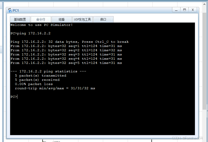
测试
PC1 和 PC2 所在的子网已通过 OSPF 通告到网络中,确保了跨区域的通信。
[R1]ping 172.16.1.1
  PING 172.16.1.1: 56  data bytes, press CTRL_C to break
    Request time out
    Reply from 172.16.1.1: bytes=56 Sequence=2 ttl=127 time=30 ms
    Reply from 172.16.1.1: bytes=56 Sequence=3 ttl=127 time=20 ms
    Reply from 172.16.1.1: bytes=56 Sequence=4 ttl=127 time=30 ms
    Reply from 172.16.1.1: bytes=56 Sequence=5 ttl=127 time=20 ms

  --- 172.16.1.1 ping statistics ---
    5 packet(s) transmitted
    4 packet(s) received
    20.00% packet loss
    round-trip min/avg/max = 20/25/30 ms

[R1]ping 172.16.2.2
  PING 172.16.2.2: 56  data bytes, press CTRL_C to break
    Request time out
    Reply from 172.16.2.2: bytes=56 Sequence=2 ttl=126 time=30 ms
    Reply from 172.16.2.2: bytes=56 Sequence=3 ttl=126 time=20 ms
    Reply from 172.16.2.2: bytes=56 Sequence=4 ttl=126 time=20 ms
    Reply from 172.16.2.2: bytes=56 Sequence=5 ttl=126 time=30 ms

  --- 172.16.2.2 ping statistics ---
    5 packet(s) transmitted
    4 packet(s) received
    20.00% packet loss
    round-trip min/avg/max = 20/25/30 ms

[R1]


 2521
2521

 被折叠的 条评论
为什么被折叠?
被折叠的 条评论
为什么被折叠?
 到【灌水乐园】发言


