


 文章详细介绍了STM32定时器的工作原理,如何通过定时器控制LED灯的闪烁和使用PWM模式实现渐亮渐灭效果。内容涉及时钟选择、计数器配置、中断设置以及实际编程示例。
(一)、STM32定时器和pwn原理:
下面是STM32定时器的工作款图

框图可以分为四个大部分(用红色笔表示出),分别是:①时钟产生器部分,②时基单元部分,③输入捕获部分、④输出比较部分。
时钟产生器部分
在第一部分时钟选择上,STM32定时器有四种时钟源选择(图中蓝色笔标识),分别是:
①内部时钟(CK_INT)
②外部时钟模式:外部触发输入(ETR)
③内部触发输入(ITRx):使用一个定时器作为另一个定时器的预分频器,如可以配置一个定时器Timer1而作为另一个定时器Timer2的预分频器。
④外部时钟模式:外部输入脚(TIx)
这四种情况可由右图表示:
其中,内部触发输入口1~4除了ITR1/ITR2/ITR3/ITR4之外还有一种情况:用一个定时器作为另一个定时器的分频器。
外部捕获比较引脚有两种,分别是:
引脚1:TI1FP1或TI1F_ED
引脚2:TI2FP2
时基单元
时基单元就是定时器框图的第二部分,它包括三个寄存器,分别是:计数器寄存器(TIMx_CNT)、预分频器寄存器(TIMx_PSC)和自动装载寄存器(TIMx_ARR)。对这三个寄存器的介绍如下:
- 计数器寄存器(TIMx_CNT)
向上计数、向下计数或者中心对齐计数;
- 计数器寄存器(TIMx_CNT)
可将时钟频率按1到65535之间的任意值进行分频,可在运行时改变其设置值;
- 自动装载寄存器(TIMx_ARR)
如果TIMx_CR1寄存器中的ARPE位为0,ARR寄存器的内容将直接写入影子寄存器;如果ARPE为1,ARR寄存器的那日同将在每次的更新时间UEV发生时,传送到影子寄存器;
如果TIM1_CR1中的UDIS位为0,当计数器产生溢出条件时,产生更新事件。
输入捕获通道
- IC1、2和IC3、4可以分别通过软件设置将其映射到TI1、TI2和TI3、TI4;
- 4个16位捕捉比较寄存器可以编程用于存放检测到对应的每一次输入捕捉时计数器的值;
- 当产生一次捕捉,相应的CCxIF标志位被置1;同时如果中断或DMA请求使能,则产生中断或DMA请求。
- 如果当CCxIF标志位已经为1,当又产生一个捕捉,则捕捉溢出标志位CCxOF将被置1。

输出比较通道(PWM)
- PWM模式运行产生:
定时器2、3和4可以产生4独立的信号
频率和占空比可以进行如下设定:
一个自动重载寄存器用于设定PWM的周期;
每个PWM通道有一个捕捉比较寄存器用于设定占空时间。
例如:产生一个40KHz的PWM信号:在定时器2的时钟为72MHz下,占空比为50% :
预分频寄存器设置为0 (计数器的时钟为TIM1CLK/(O+1)),自动重载寄存器设为 1799,CCRx寄存器设为899。
- 两种可设置PWM模式:
边沿对齐模式
中心对齐模式

(二)、使用定时器控制led灯的闪烁
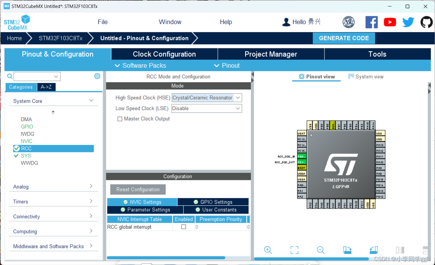
1、使用STM32CubeMX新建一个工程文件
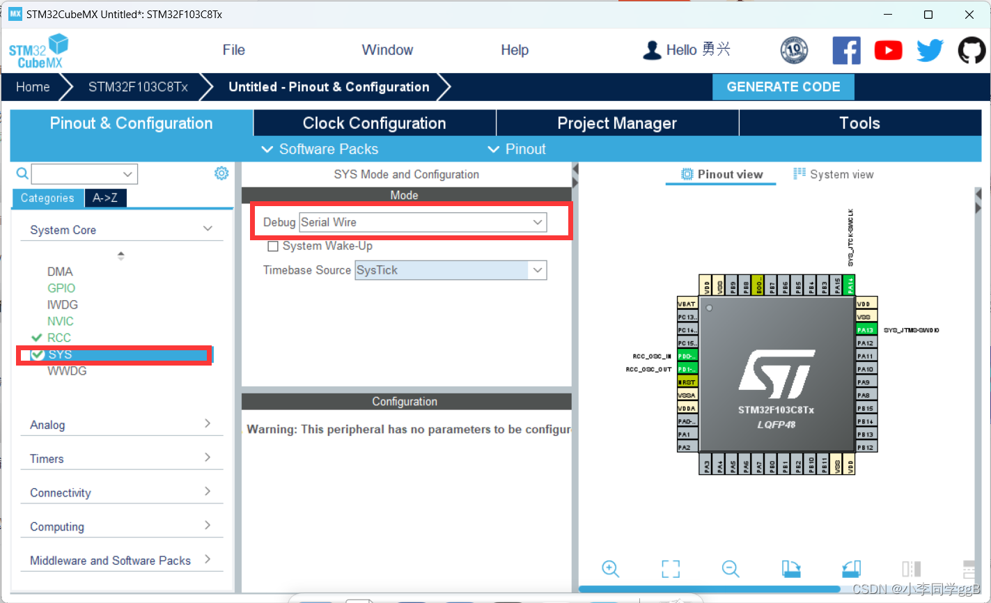
芯片使用STM32F103C8T6,配置RCC和SYS
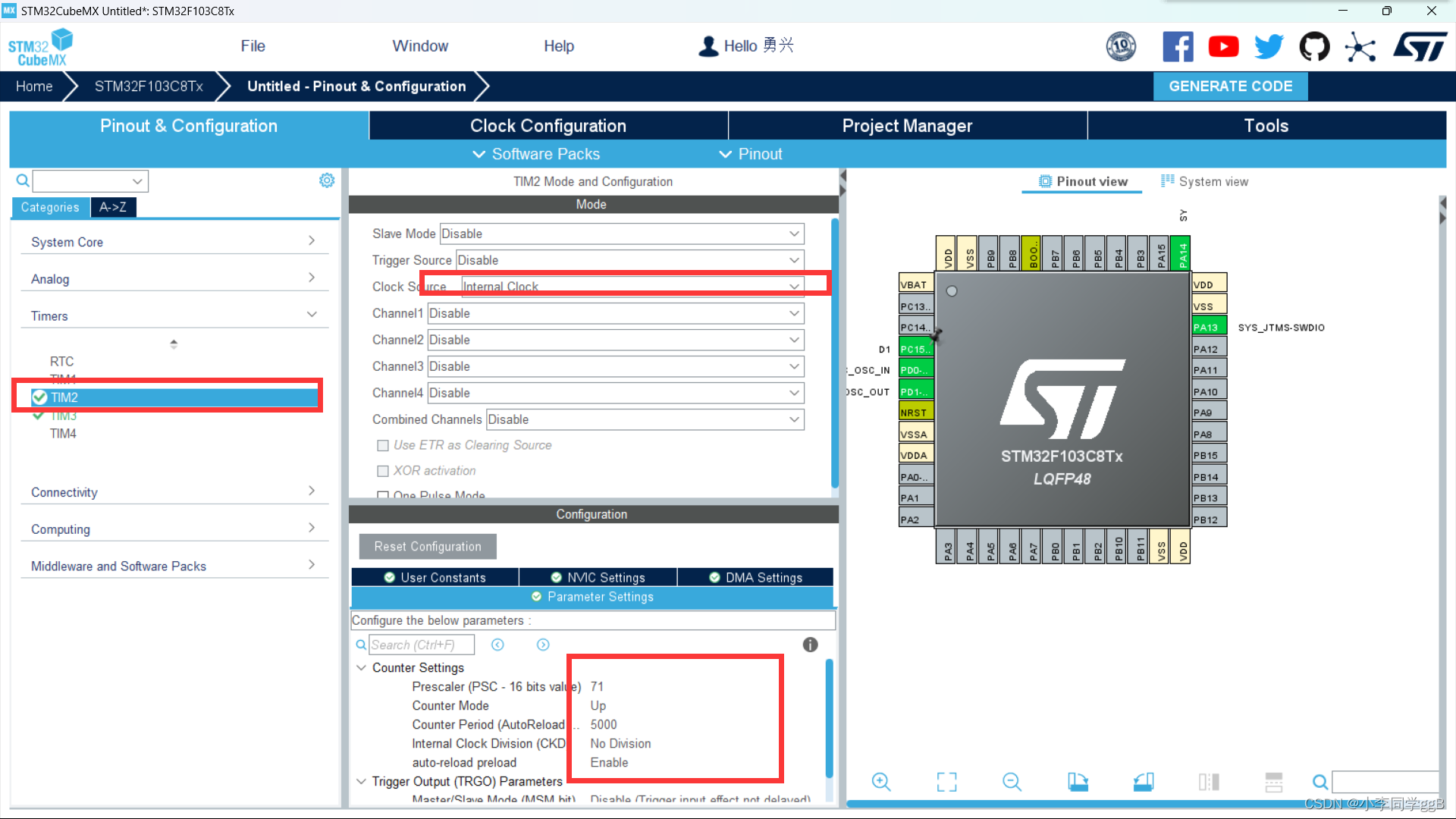
2、配置IO和定时器
将pc15配置为output输出,并且更改标签为D1

选定时器2,配置Clock Source为Internal Clock,分频系数为71技术周期5000,然后设置为能够自动重载 。
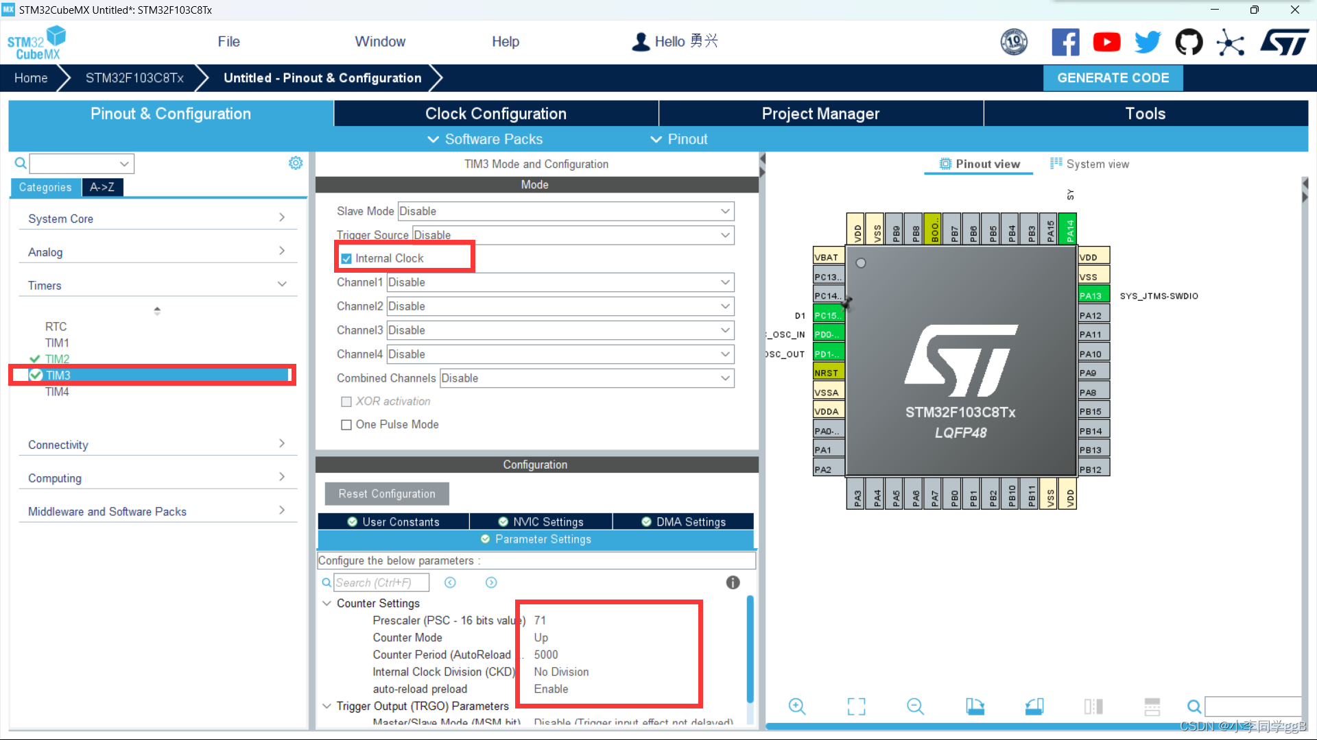
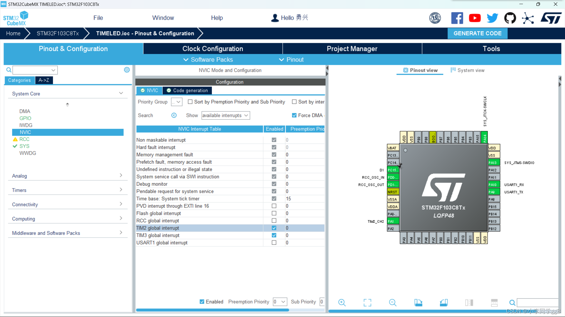
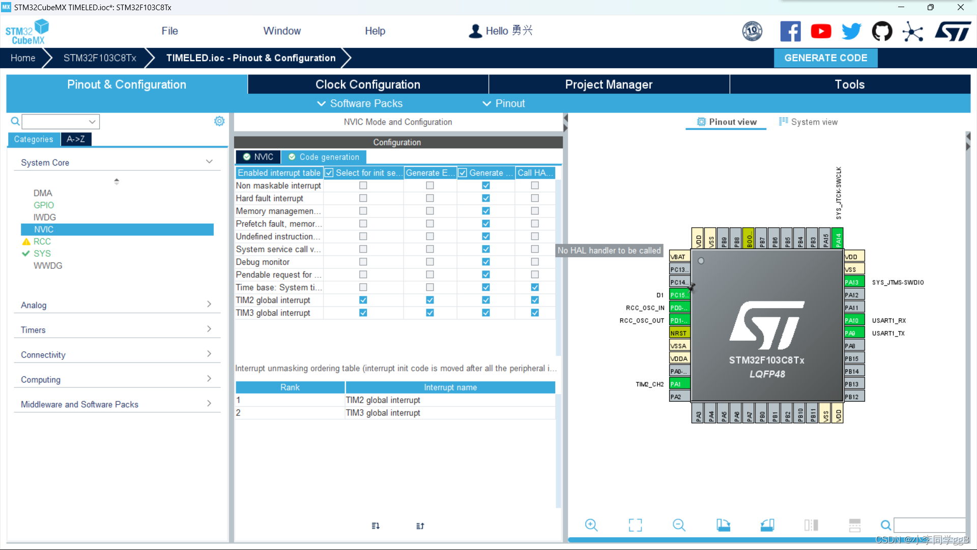
3、配置中断

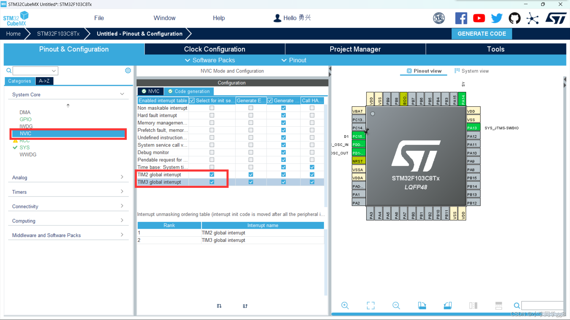
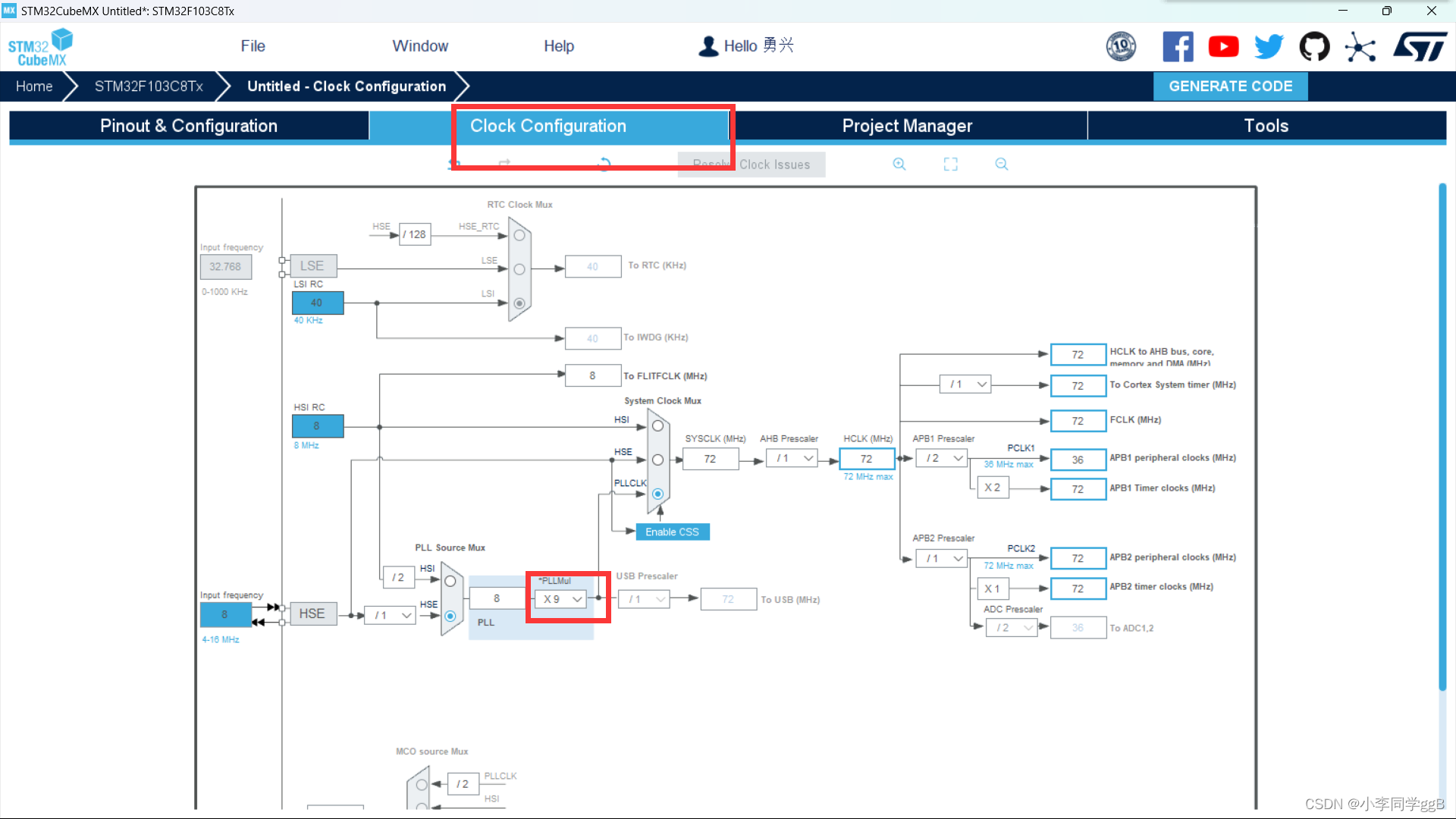
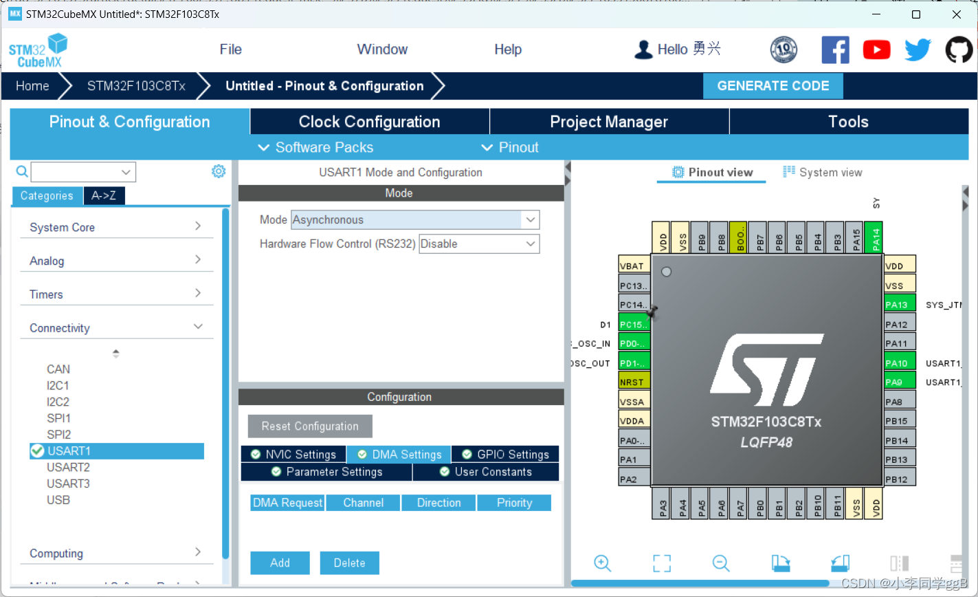
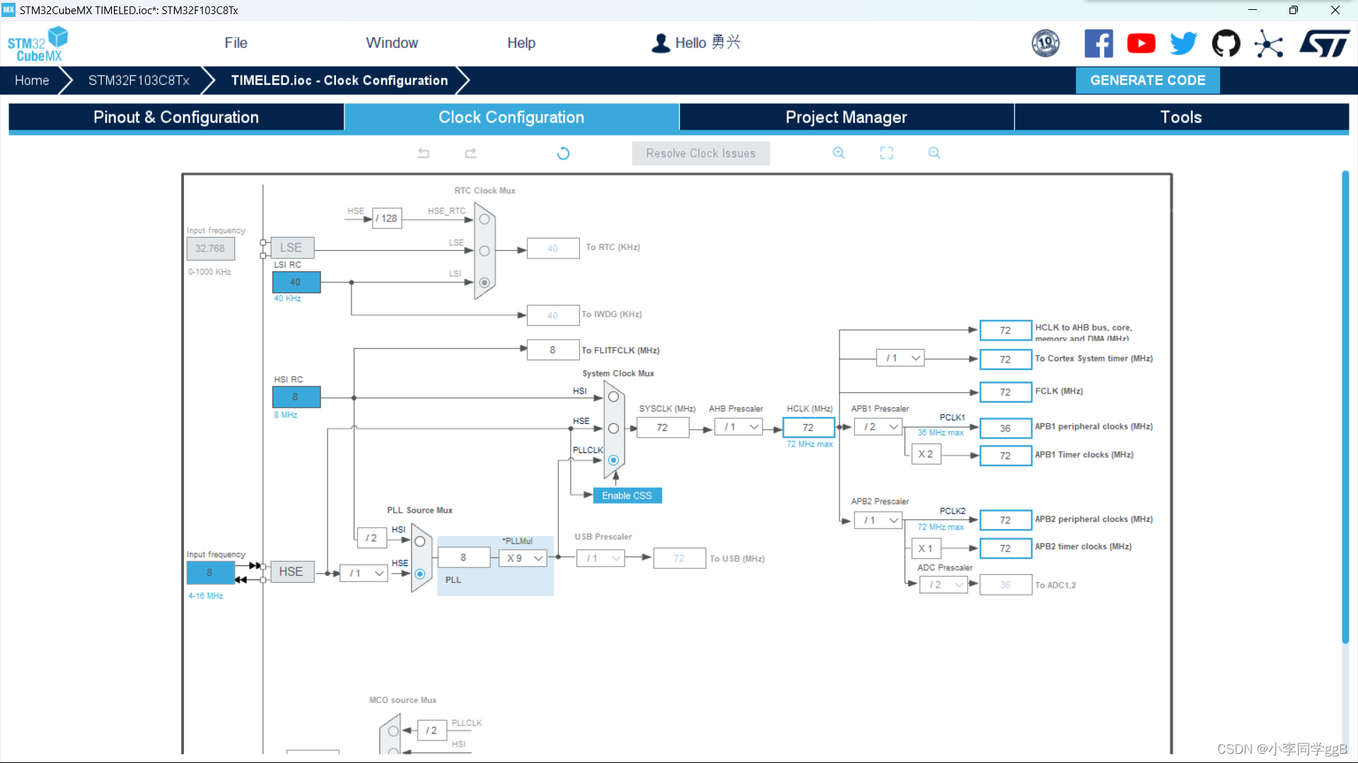
4、时钟配置和USART配置
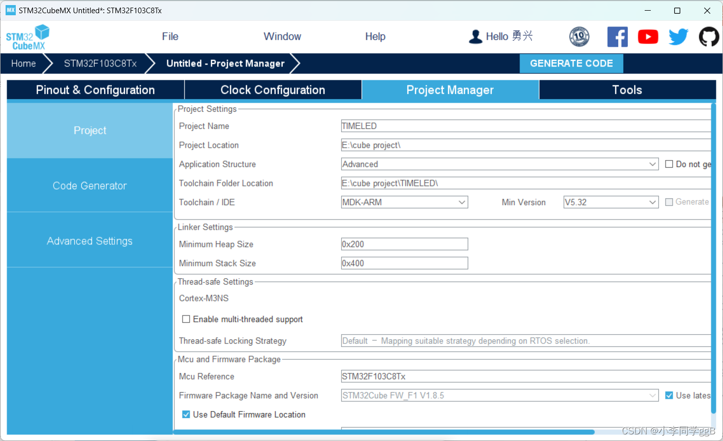
5、生成文件
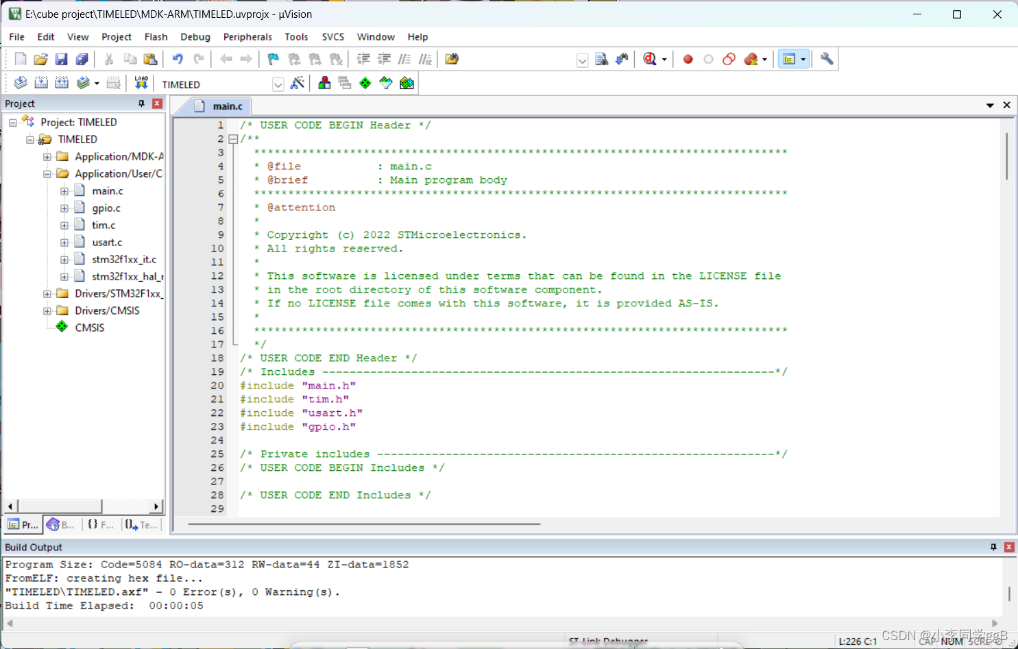
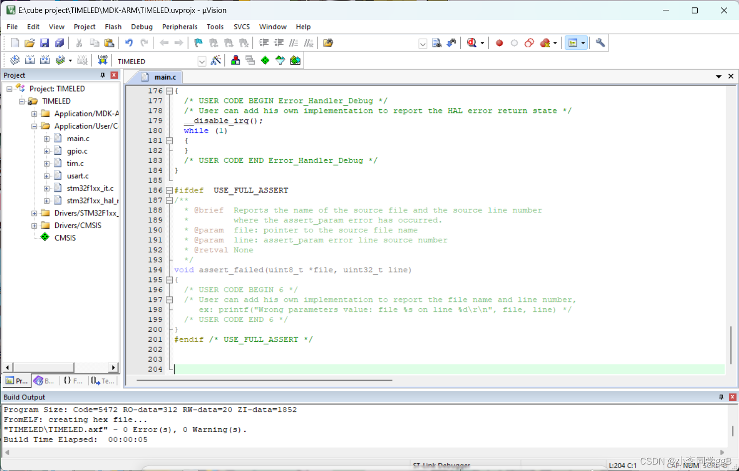
 6、总代码及编译
/* USER CODE BEGIN Header */
/**
  ******************************************************************************
  * @file           : main.c
  * @brief          : Main program body
  ******************************************************************************
  * @attention
  *
  * Copyright (c) 2022 STMicroelectronics.
  * All rights reserved.
  *
  * This software is licensed under terms that can be found in the LICENSE file
  * in the root directory of this software component.
  * If no LICENSE file comes with this software, it is provided AS-IS.
  *
  ******************************************************************************
  */
/* USER CODE END Header */
/* Includes ------------------------------------------------------------------*/
#include "main.h"
#include "tim.h"
#include "usart.h"
#include "gpio.h"

/* Private includes ----------------------------------------------------------*/
/* USER CODE BEGIN Includes */

/* USER CODE END Includes */

/* Private typedef -----------------------------------------------------------*/
/* USER CODE BEGIN PTD */

/* USER CODE END PTD */

/* Private define ------------------------------------------------------------*/
/* USER CODE BEGIN PD */
/* USER CODE END PD */

/* Private macro -------------------------------------------------------------*/
/* USER CODE BEGIN PM */

/* USER CODE END PM */

/* Private variables ---------------------------------------------------------*/

/* USER CODE BEGIN PV */

/* USER CODE END PV */

/* Private function prototypes -----------------------------------------------*/
void SystemClock_Config(void);
static void MX_NVIC_Init(void);
/* USER CODE BEGIN PFP */

/* USER CODE END PFP */

/* Private user code ---------------------------------------------------------*/
/* USER CODE BEGIN 0 */

/* USER CODE END 0 */

/**
  * @brief  The application entry point.
  * @retval int
  */
  uint8_t hello[20]="hello windows!\r\n";
int main(void)
{
  /* USER CODE BEGIN 1 */

  /* USER CODE END 1 */

  /* MCU Configuration--------------------------------------------------------*/

  /* Reset of all peripherals, Initializes the Flash interface and the Systick. */
  HAL_Init();

  /* USER CODE BEGIN Init */

  /* USER CODE END Init */

  /* Configure the system clock */
  SystemClock_Config();

  /* USER CODE BEGIN SysInit */

  /* USER CODE END SysInit */

  /* Initialize all configured peripherals */
  MX_GPIO_Init();
  MX_TIM2_Init();
  MX_TIM3_Init();
  MX_USART1_UART_Init();

  /* Initialize interrupts */
  MX_NVIC_Init();
	HAL_TIM_Base_Start_IT(&htim2);
	HAL_TIM_Base_Start_IT(&htim3);

  /* USER CODE BEGIN 2 */

  /* USER CODE END 2 */

  /* Infinite loop */
  /* USER CODE BEGIN WHILE */
  while (1)
  {
    /* USER CODE END WHILE */

    /* USER CODE BEGIN 3 */
  }
  /* USER CODE END 3 */
}

/**
  * @brief System Clock Configuration
  * @retval None
  */
void SystemClock_Config(void)
{
  RCC_OscInitTypeDef RCC_OscInitStruct = {0};
  RCC_ClkInitTypeDef RCC_ClkInitStruct = {0};

  /** Initializes the RCC Oscillators according to the specified parameters
  * in the RCC_OscInitTypeDef structure.
  */
  RCC_OscInitStruct.OscillatorType = RCC_OSCILLATORTYPE_HSE;
  RCC_OscInitStruct.HSEState = RCC_HSE_ON;
  RCC_OscInitStruct.HSEPredivValue = RCC_HSE_PREDIV_DIV1;
  RCC_OscInitStruct.HSIState = RCC_HSI_ON;
  RCC_OscInitStruct.PLL.PLLState = RCC_PLL_ON;
  RCC_OscInitStruct.PLL.PLLSource = RCC_PLLSOURCE_HSE;
  RCC_OscInitStruct.PLL.PLLMUL = RCC_PLL_MUL9;
  if (HAL_RCC_OscConfig(&RCC_OscInitStruct) != HAL_OK)
  {
    Error_Handler();
  }

  /** Initializes the CPU, AHB and APB buses clocks
  */
  RCC_ClkInitStruct.ClockType = RCC_CLOCKTYPE_HCLK|RCC_CLOCKTYPE_SYSCLK
                              |RCC_CLOCKTYPE_PCLK1|RCC_CLOCKTYPE_PCLK2;
  RCC_ClkInitStruct.SYSCLKSource = RCC_SYSCLKSOURCE_PLLCLK;
  RCC_ClkInitStruct.AHBCLKDivider = RCC_SYSCLK_DIV1;
  RCC_ClkInitStruct.APB1CLKDivider = RCC_HCLK_DIV2;
  RCC_ClkInitStruct.APB2CLKDivider = RCC_HCLK_DIV1;

  if (HAL_RCC_ClockConfig(&RCC_ClkInitStruct, FLASH_LATENCY_2) != HAL_OK)
  {
    Error_Handler();
  }
}

/**
  * @brief NVIC Configuration.
  * @retval None
  */
static void MX_NVIC_Init(void)
{
  /* TIM2_IRQn interrupt configuration */
  HAL_NVIC_SetPriority(TIM2_IRQn, 0, 0);
  HAL_NVIC_EnableIRQ(TIM2_IRQn);
  /* TIM3_IRQn interrupt configuration */
  HAL_NVIC_SetPriority(TIM3_IRQn, 0, 0);
  HAL_NVIC_EnableIRQ(TIM3_IRQn);
}

/* USER CODE BEGIN 4 */
void HAL_TIM_PeriodElapsedCallback(TIM_HandleTypeDef *htim)
{
	static uint32_t time_cnt =0;
	static uint32_t time_cntck =0;
	if(htim->Instance == TIM2)
	{
		if(++time_cnt >= 400)
		{
			time_cnt =0;
			HAL_GPIO_TogglePin(D1_GPIO_Port,D1_Pin);
		}
	}
	if(htim->Instance == TIM3)
	{
		if(++time_cntck >= 1000)
		{
			time_cntck =0;
    HAL_UART_Transmit(&huart1,hello,20,100000);
		}

	}
}

/* USER CODE END 4 */
/**
  * @brief  This function is executed in case of error occurrence.
  * @retval None
  */
void Error_Handler(void)
{
  /* USER CODE BEGIN Error_Handler_Debug */
  /* User can add his own implementation to report the HAL error return state */
  __disable_irq();
  while (1)
  {
  }
  /* USER CODE END Error_Handler_Debug */
}

#ifdef  USE_FULL_ASSERT
/**
  * @brief  Reports the name of the source file and the source line number
  *         where the assert_param error has occurred.
  * @param  file: pointer to the source file name
  * @param  line: assert_param error line source number
  * @retval None
  */
void assert_failed(uint8_t *file, uint32_t line)
{
  /* USER CODE BEGIN 6 */
  /* User can add his own implementation to report the file name and line number,
     ex: printf("Wrong parameters value: file %s on line %d\r\n", file, line) */
  /* USER CODE END 6 */
}
#endif /* USE_FULL_ASSERT */
7、运行效果
D34BA
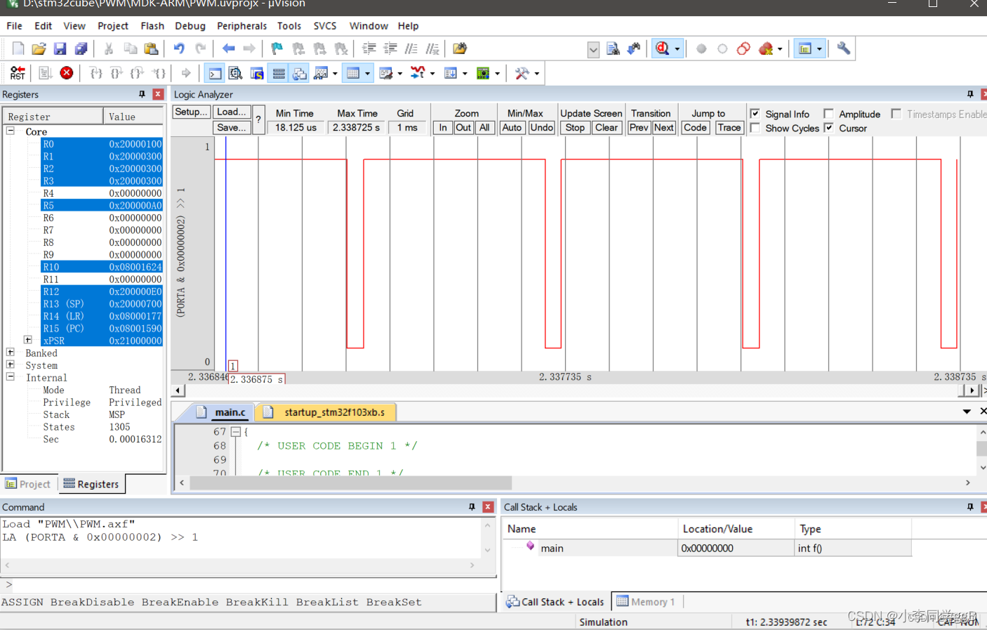
(三)、采用定时器pwm模式,让 LED 以呼吸灯方式渐亮渐灭。使用Keil虚拟示波器,观察 pwm输出波形
1、HAL库建立
1)配置
1)SYS和RCC配置和上面定时器控制LED一样,这里就不多说
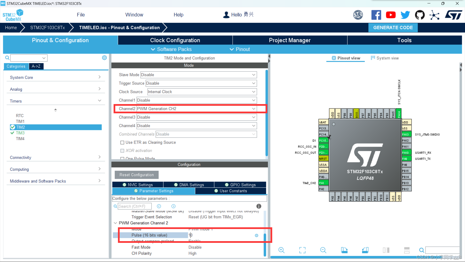
2)定时器配置
3)配置中断
4)配置USART

5)配置时钟
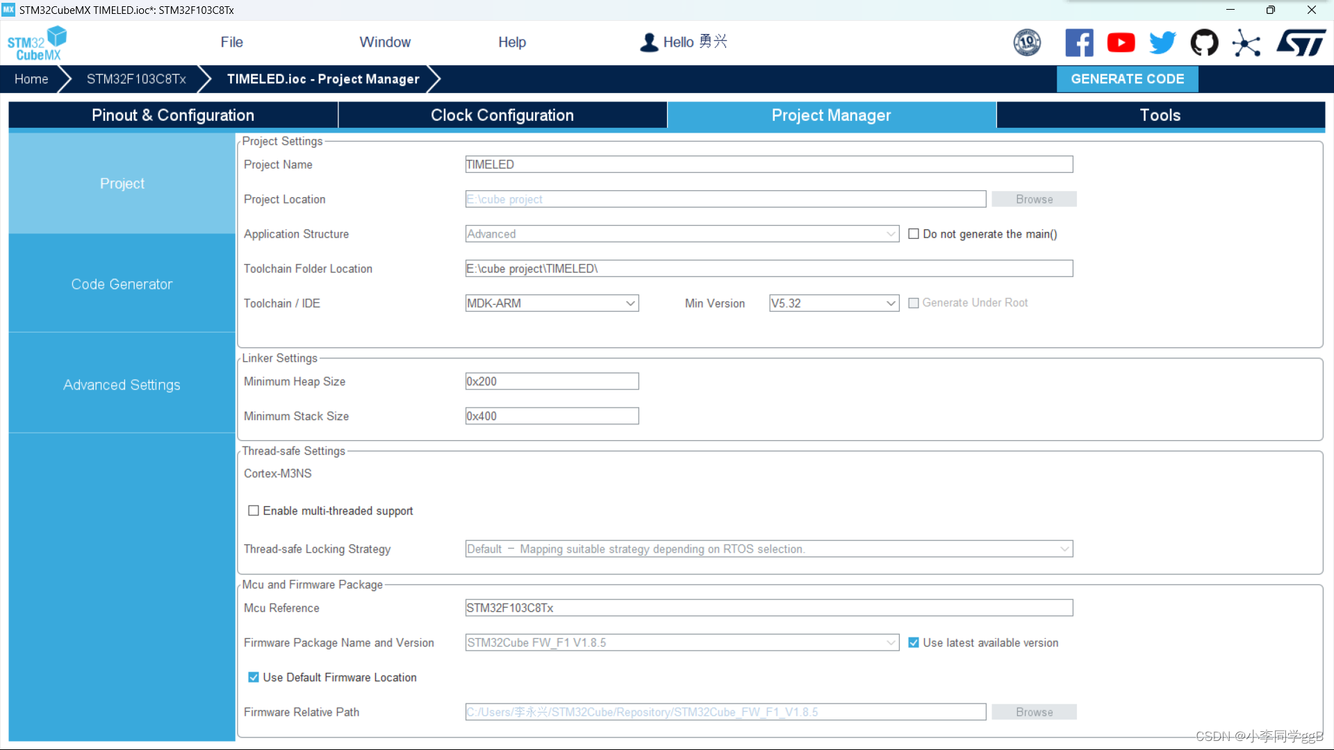
2、项目配置
2、总代码3
/* USER CODE BEGIN Header */
/**
  ******************************************************************************
  * @file           : main.c
  * @brief          : Main program body
  ******************************************************************************
  * @attention
  *
  * Copyright (c) 2022 STMicroelectronics.
  * All rights reserved.
  *
  * This software is licensed under terms that can be found in the LICENSE file
  * in the root directory of this software component.
  * If no LICENSE file comes with this software, it is provided AS-IS.
  *
  ******************************************************************************
  */
/* USER CODE END Header */
/* Includes ------------------------------------------------------------------*/
#include "main.h"
#include "tim.h"
#include "usart.h"
#include "gpio.h"

/* Private includes ----------------------------------------------------------*/
/* USER CODE BEGIN Includes */

/* USER CODE END Includes */

/* Private typedef -----------------------------------------------------------*/
/* USER CODE BEGIN PTD */

/* USER CODE END PTD */

/* Private define ------------------------------------------------------------*/
/* USER CODE BEGIN PD */
/* USER CODE END PD */

/* Private macro -------------------------------------------------------------*/
/* USER CODE BEGIN PM */

/* USER CODE END PM */

/* Private variables ---------------------------------------------------------*/

/* USER CODE BEGIN PV */

/* USER CODE END PV */
uint16_t duty_num = 10;
/* Private function prototypes -----------------------------------------------*/
void SystemClock_Config(void);
static void MX_NVIC_Init(void);
/* USER CODE BEGIN PFP */

/* USER CODE END PFP */

/* Private user code ---------------------------------------------------------*/
/* USER CODE BEGIN 0 */

/* USER CODE END 0 */

/**
  * @brief  The application entry point.
  * @retval int
  */
int main(void)
{
  /* USER CODE BEGIN 1 */

  /* USER CODE END 1 */

  /* MCU Configuration--------------------------------------------------------*/

  /* Reset of all peripherals, Initializes the Flash interface and the Systick. */
  HAL_Init();

  /* USER CODE BEGIN Init */

  /* USER CODE END Init */

  /* Configure the system clock */
  SystemClock_Config();

  /* USER CODE BEGIN SysInit */

  /* USER CODE END SysInit */

  /* Initialize all configured peripherals */
  MX_GPIO_Init();
  MX_TIM2_Init();
  MX_USART1_UART_Init();

  /* Initialize interrupts */
  MX_NVIC_Init();
  /* USER CODE BEGIN 2 */
  HAL_TIM_PWM_Start(&htim2,TIM_CHANNEL_2);
  /* USER CODE END 2 */

  /* Infinite loop */
  /* USER CODE BEGIN WHILE */
  while (1)
  {
    /* USER CODE END WHILE */

    /* USER CODE BEGIN 3 */
		HAL_Delay(50);
		duty_num = duty_num + 10;
		if(duty_num > 500)
		{
			duty_num = 0;
		}
		__HAL_TIM_SetCompare(&htim2,TIM_CHANNEL_2,duty_num);
  }
  /* USER CODE END 3 */
}

/**
  * @brief System Clock Configuration
  * @retval None
  */
void SystemClock_Config(void)
{
  RCC_OscInitTypeDef RCC_OscInitStruct = {0};
  RCC_ClkInitTypeDef RCC_ClkInitStruct = {0};

  /** Initializes the RCC Oscillators according to the specified parameters
  * in the RCC_OscInitTypeDef structure.
  */
  RCC_OscInitStruct.OscillatorType = RCC_OSCILLATORTYPE_HSE;
  RCC_OscInitStruct.HSEState = RCC_HSE_ON;
  RCC_OscInitStruct.HSEPredivValue = RCC_HSE_PREDIV_DIV1;
  RCC_OscInitStruct.HSIState = RCC_HSI_ON;
  RCC_OscInitStruct.PLL.PLLState = RCC_PLL_ON;
  RCC_OscInitStruct.PLL.PLLSource = RCC_PLLSOURCE_HSE;
  RCC_OscInitStruct.PLL.PLLMUL = RCC_PLL_MUL9;
  if (HAL_RCC_OscConfig(&RCC_OscInitStruct) != HAL_OK)
  {
    Error_Handler();
  }

  /** Initializes the CPU, AHB and APB buses clocks
  */
  RCC_ClkInitStruct.ClockType = RCC_CLOCKTYPE_HCLK|RCC_CLOCKTYPE_SYSCLK
                              |RCC_CLOCKTYPE_PCLK1|RCC_CLOCKTYPE_PCLK2;
  RCC_ClkInitStruct.SYSCLKSource = RCC_SYSCLKSOURCE_PLLCLK;
  RCC_ClkInitStruct.AHBCLKDivider = RCC_SYSCLK_DIV1;
  RCC_ClkInitStruct.APB1CLKDivider = RCC_HCLK_DIV2;
  RCC_ClkInitStruct.APB2CLKDivider = RCC_HCLK_DIV1;

  if (HAL_RCC_ClockConfig(&RCC_ClkInitStruct, FLASH_LATENCY_2) != HAL_OK)
  {
    Error_Handler();
  }
}

/**
  * @brief NVIC Configuration.
  * @retval None
  */
static void MX_NVIC_Init(void)
{
  /* TIM2_IRQn interrupt configuration */
  HAL_NVIC_SetPriority(TIM2_IRQn, 0, 0);
  HAL_NVIC_EnableIRQ(TIM2_IRQn);
}

/* USER CODE BEGIN 4 */

/* USER CODE END 4 */

/**
  * @brief  This function is executed in case of error occurrence.
  * @retval None
  */
void Error_Handler(void)
{
  /* USER CODE BEGIN Error_Handler_Debug */
  /* User can add his own implementation to report the HAL error return state */
  __disable_irq();
  while (1)
  {
  }
  /* USER CODE END Error_Handler_Debug */
}

#ifdef  USE_FULL_ASSERT
/**
  * @brief  Reports the name of the source file and the source line number
  *         where the assert_param error has occurred.
  * @param  file: pointer to the source file name
  * @param  line: assert_param error line source number
  * @retval None
  */
void assert_failed(uint8_t *file, uint32_t line)
{
  /* USER CODE BEGIN 6 */
  /* User can add his own implementation to report the file name and line number,
     ex: printf("Wrong parameters value: file %s on line %d\r\n", file, line) */
  /* USER CODE END 6 */
}
#endif /* USE_FULL_ASSERT */
3、 编译并烧录
STM32灯闪烁
4、输出PWM波形


 1151
1151

 被折叠的 条评论
为什么被折叠?
被折叠的 条评论
为什么被折叠?
 到【灌水乐园】发言


