


目录
1.完成LED流水灯实验(标准库)
1.1新建工程
工程模板
链接:https://pan.baidu.com/s/1aE4Dd-9YA2b2BkAbt_bDwg
提取码:9962
下载完成后解压就得到工程模板,根据具体项目名称修改文件夹的名称

接线图:
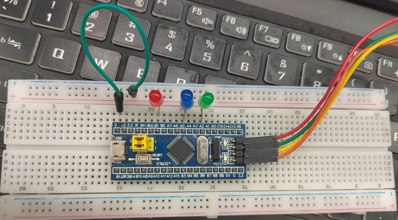
1.2代码编写
利用PA2,PA5,PB1实现流水灯
流程图:
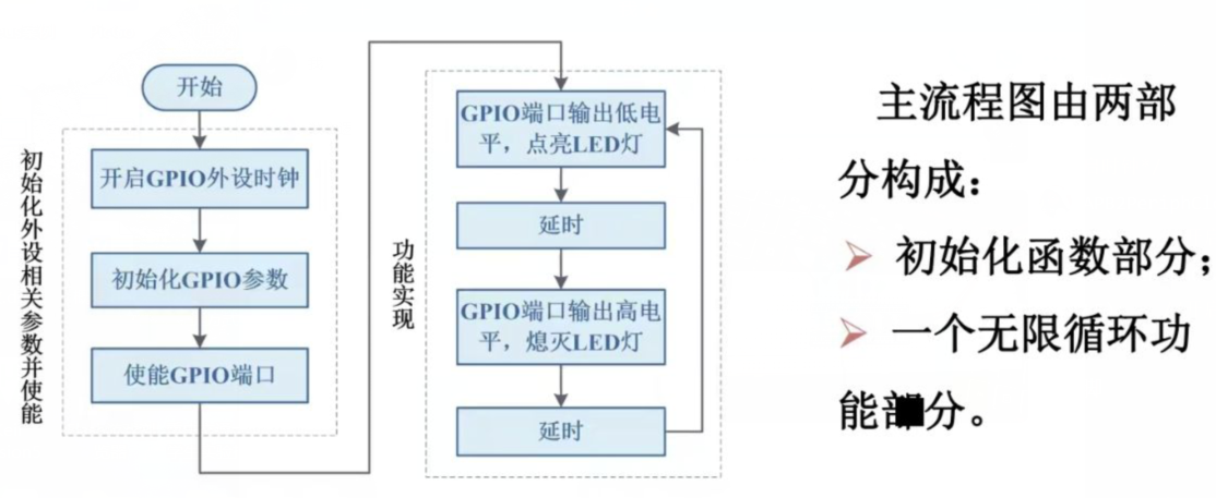
开启RCC时钟
/*开启时钟*/
RCC_APB2PeriphClockCmd(RCC_APB2Periph_GPIOA, ENABLE);	//开启GPIOA的时钟
RCC_APB2PeriphClockCmd(RCC_APB2Periph_GPIOB, ENABLE);	//开启GPIOB的时钟
初始化管脚
	GPIO_InitTypeDef GPIO_InitStructure;					//定义结构体变量
/*GPIOA初始化*/
	GPIO_InitStructure.GPIO_Mode = GPIO_Mode_Out_PP;		//GPIO模式,赋值为推挽输出模式
	GPIO_InitStructure.GPIO_Pin = GPIO_Pin_2|GPIO_Pin_5;	//GPIO引脚,赋值为引脚2和引脚5

	GPIO_InitStructure.GPIO_Speed = GPIO_Speed_2MHz;		//GPIO速度,赋值为2MHz

	GPIO_Init(GPIOA, &GPIO_InitStructure);					//将赋值后的构体变量传递给GPIO_Init函数
															//函数内部会自动根据结构体的参数配置相应寄存器
															//实现GPIOA的初始化
/*GPIOB初始化*/
	GPIO_InitStructure.GPIO_Mode = GPIO_Mode_Out_PP;		//GPIO模式,赋值为推挽输出模式
	GPIO_InitStructure.GPIO_Pin = GPIO_Pin_1;	//GPIO引脚,赋值为引脚2和引脚5
	GPIO_InitStructure.GPIO_Speed = GPIO_Speed_2MHz;		//GPIO速度,赋值为2MHz
	GPIO_Init(GPIOB, &GPIO_InitStructure);
实现流水灯
void Light_PA2()//连接在PA2口的led亮
{
	GPIO_WriteBit(GPIOA,GPIO_Pin_2,1);
	GPIO_WriteBit(GPIOA,GPIO_Pin_5,0);
	GPIO_WriteBit(GPIOB,GPIO_Pin_1,0);
}
void Light_PA5()//连接在PA5口的led亮
{
	GPIO_WriteBit(GPIOA,GPIO_Pin_2,0);
	GPIO_WriteBit(GPIOA,GPIO_Pin_5,1);
	GPIO_WriteBit(GPIOB,GPIO_Pin_1,0);
}
void Light_PB1()//连接在PB1口的led亮
{
	GPIO_WriteBit(GPIOA,GPIO_Pin_2,0);
	GPIO_WriteBit(GPIOA,GPIO_Pin_5,0);
	GPIO_WriteBit(GPIOB,GPIO_Pin_1,1);
}
while(1)
{
   		Light_PA2();
		Delay_s(1);
		Light_PA5();
		Delay_s(1);
		Light_PB1();
		Delay_s(1);
}
完整代码
#include "stm32f10x.h"
#include "Delay.h"
void Light_PA2()
{
	GPIO_WriteBit(GPIOA,GPIO_Pin_2,1);
	GPIO_WriteBit(GPIOA,GPIO_Pin_5,0);
	GPIO_WriteBit(GPIOB,GPIO_Pin_1,0);
}
void Light_PA5()
{
	GPIO_WriteBit(GPIOA,GPIO_Pin_2,0);
	GPIO_WriteBit(GPIOA,GPIO_Pin_5,1);
	GPIO_WriteBit(GPIOB,GPIO_Pin_1,0);
}
void Light_PB1()
{
	GPIO_WriteBit(GPIOA,GPIO_Pin_2,0);
	GPIO_WriteBit(GPIOA,GPIO_Pin_5,0);
	GPIO_WriteBit(GPIOB,GPIO_Pin_1,1);
}
int main(void)
{
	RCC_APB2PeriphClockCmd(RCC_APB2Periph_GPIOA, ENABLE);
	RCC_APB2PeriphClockCmd(RCC_APB2Periph_GPIOB, ENABLE);
	GPIO_InitTypeDef GPIO_InitStructure1;

	GPIO_InitStructure1.GPIO_Mode = GPIO_Mode_Out_PP;
	GPIO_InitStructure1.GPIO_Pin = GPIO_Pin_All;
	GPIO_InitStructure1.GPIO_Speed = GPIO_Speed_2MHz;
	GPIO_Init(GPIOA, &GPIO_InitStructure1);

	GPIO_InitTypeDef GPIO_InitStructure2;
	GPIO_InitStructure2.GPIO_Mode = GPIO_Mode_Out_PP;
	GPIO_InitStructure2.GPIO_Pin = GPIO_Pin_1;
	GPIO_InitStructure2.GPIO_Speed = GPIO_Speed_2MHz;
	GPIO_Init(GPIOB, &GPIO_InitStructure2);
	/*默认设定3个led均为熄灭状态*/
    GPIO_WriteBit(GPIOA,GPIO_Pin_2,0);
	GPIO_WriteBit(GPIOA,GPIO_Pin_5,0);
	GPIO_WriteBit(GPIOB,GPIO_Pin_1,0);
	while (1)
	{
		Light_PA2();//PA2的led亮
		Delay_s(1);
		Light_PA5();//PA5的led亮
		Delay_s(1);
		Light_PB1();//PB1的led亮
		Delay_s(1);
	}
}
1.3效果展示
2.串口通信
STM32F103C8T6引脚图:
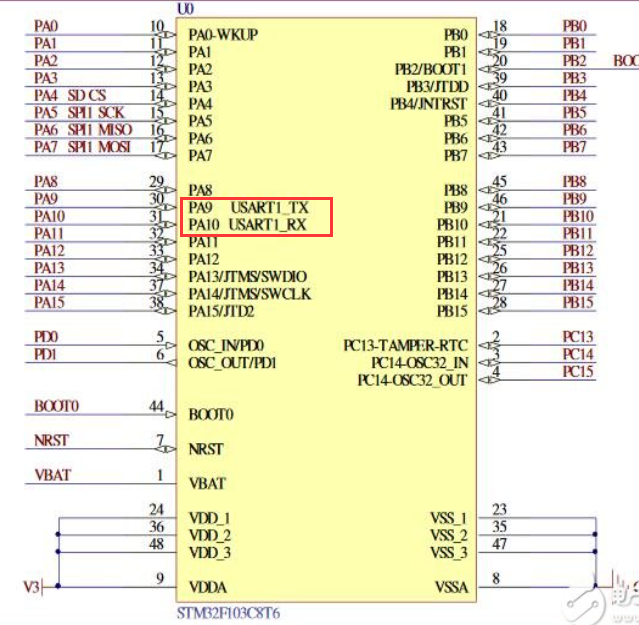
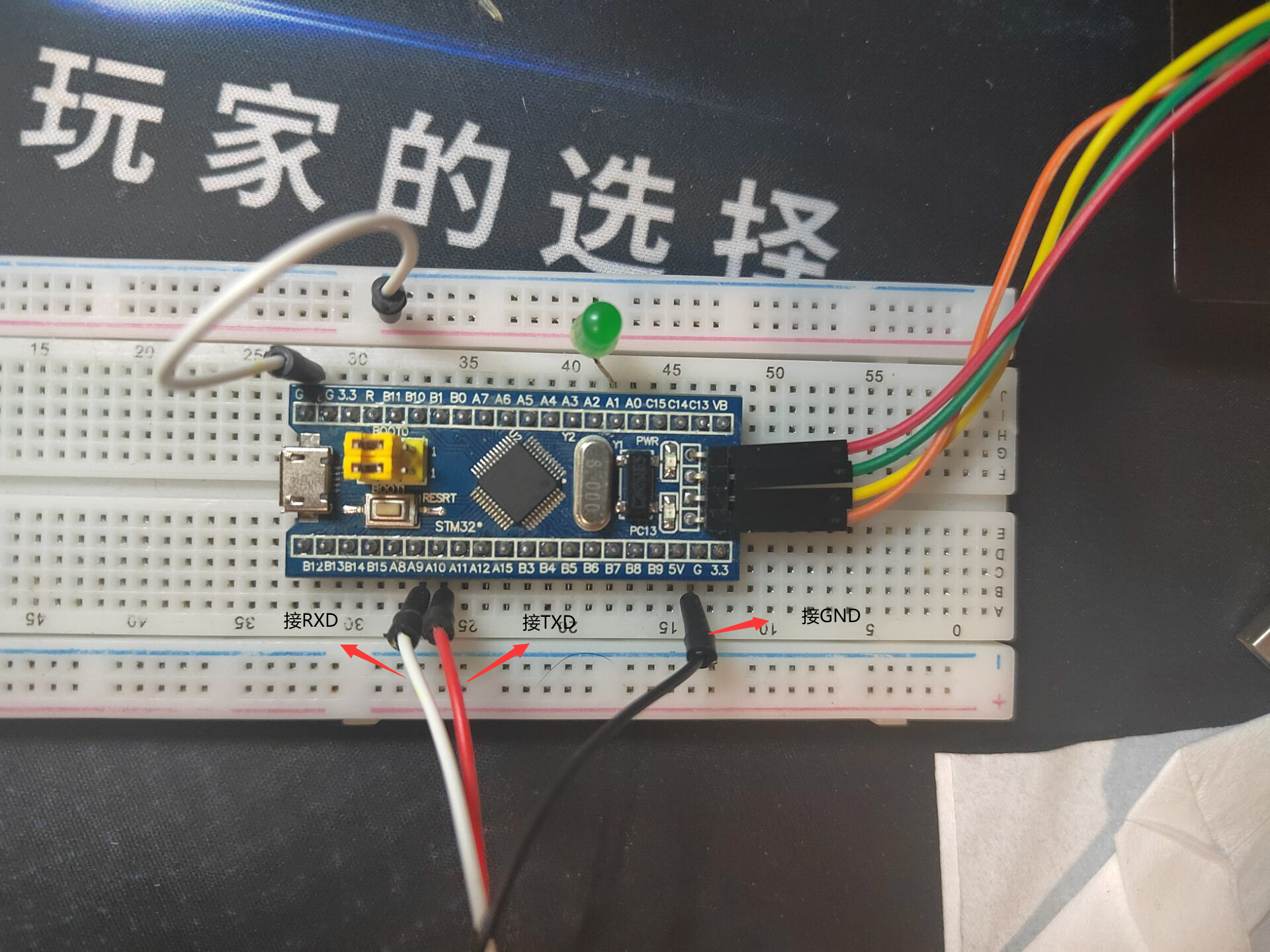
引脚连接方式:
| STM32F103C8T6 | 串口 |
|---|---|
| PA9 (USART1-TX) | RXD |
| PA10 (USART1-RX) | TXD |
| GND | GND |
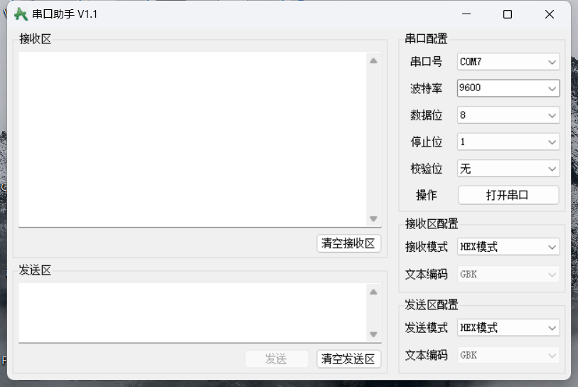
串口助手:
链接:https://pan.baidu.com/s/18q9ZRMhTC5aibyUgrZ-Zhg
提取码:9962
波特率:每秒传输的二进制位数,单位为比特每秒(bit/s,bps),是衡量串行数据传输速度快慢的指标。
字符速率:每秒所传输的字符数:波特率=字符速率×每个字符包含的位数
2.1USART串口应用编程步骤
(1)声明GPIO和USART初始化结构体
USART_InitTypeDef USART_InitStructure;
(2)串口所用的GPIO时钟使能,串口时钟使能
RCC_APB2PeriphClockCmd(RCC_APB2Periph_USART1|RCC_APB2Periph_GPIOA,ENABLE);//使能USART1、 GPIOA的时钟
(3)设置IO引脚功能为复用推挽输出、浮空输入
//USART1_TX(PA9),配置为复用推挽输出,并初始化PA9
 GPIO_InitStructure.GPIO_Pin  =GPIO_Pin_9;
 GPIO_InitStructure.GPIO_Speed=GPIO_Speed_50MHz;
 GPIO_InitStructure.GPIO_Mode =GPIO_Mode_AF_PP;//复用推挽输出
 GPIO_Init(GPIOA,&GPIO_InitStructure );
//USART1_RX(PA10),配置为浮空输入,并初始化PA10
 GPIO_InitStructure.GPIO_Pin = GPIO_Pin_10;
 GPIO_InitStructure.GPIO_Mode=GPIO_Mode_IN_FLOATING;//浮空输入
 GPIO_Init(GPIOA,&GPIO_InitStructure);//初始化PA10
(4)设置波特率,设置数据格式。数据位、停止位、校验位
设置波特率
USART_InitStructure.USART_BaudRate = 4800; //设置串口波特率为4800
USART_InitStructure.USART_BaudRate = 9600;
USART_InitStructure.USART_BaudRate = 38400;
USART_InitStructure.USART_BaudRate = 115200;
设置数据位
USART_InitStructure.USART_WordLength= USART_WordLength_8b;//设置数据位占8位
USART_InitStructure.USART_WordLength= USART_WordLength_9b;设置数据位占9位
设置停止位
USART_InitStructure.USART_StopBits= USART_StopBits_0_5; //设置停止位占0.5位
USART_InitStructure.USART_StopBits= USART_StopBits_1; //设置停止位占1位
USART_InitStructure.USART_StopBits= USART_StopBits_1_5; //设置停止位占1.5位
USART_InitStructure.USART_StopBits= USART_StopBits_2; //设置停止位占2位
设置校验位
USART_InitStructure.USART_Parity = USART_Parity_No; //无奇偶校验位
USART_InitStructure.USART_Parity = USART_Parity_Odd; //奇校验位
USART_InitStructure.USART_Parity = USART_Parity_Even; //偶校验位
设置串口的工作模式
USART_InitStructure.USART_Mode=USART_Mode_Rx;//只接收数据
USART_InitStructure.USART_Mode=USART_Mode_Tx;//只发送数据
USART_InitStructure.USART_Mode=USART_Mode_Rx|USART_Mode_Tx;//接受和发送数据
(5)使用串口初始化函数USART Init[初始化相应串口
USART_Init(USART1, &USART_InitStructure);//初始化串口1 USART1
(6)利用串口使能函数USART Cmd)使能相应串口
USART_Cmd(USART1,ENABLE);//使能USART1串口
(7)应用程序编写
若使用中断,则编写串口中断函数
void USART1_ IRQHandler(void)
{

}
补充:
数据的发送
USART_SendData(USART1,data);//发送字符
while (USART_GetFlagStatus(USART1, USART_FLAG_TXE) == RESET);//等待发送完成
数据的接收
while(1)
{
    // 检查是否接收到新数据
    if(USART_GetFlagStatus(USART1, USART_IT_RXNE) == SET)//接受数据寄存器不为空,证明收到数据
    {
        // 读取数据
        uint8_t receivedChar= USART_ReceiveData(USART1);
        // 这里可以根据需要处理接收到的数据,例如存储、分析或显示等
        // 示例:简单地将接收到的字符打印到串口(如果需要)
        // 注意:这一步是可选的,取决于您的具体需求
        // USART_SendData(USART1, receivedChar);

        // 进一步处理receivedChar...
    }
}
}
2.2hello windows!
问题描述:STM32系统给上位机(win10)连续发送“hello windows!”。win10采用“串口助手”工具接收(设置波特率为9600,1位停止位,无校验位)
代码部分:
#include "stm32f10x.h"
#include "Delay.h"
void hellowindows()
{
	int i;
	char a [13]={'h','e','l','l','w','i','n','d','o','w','s','!'};
	for (i = 0; i < 13; i++)
	{
	USART_SendData(USART1,a[i]);
	while (USART_GetFlagStatus(USART1, USART_FLAG_TXE) == RESET);
	}
}
int main(void)
{
	USART_InitTypeDef USART_InitStructure;
	RCC_APB2PeriphClockCmd(RCC_APB2Periph_USART1|RCC_APB2Periph_GPIOA,ENABLE);

	GPIO_InitTypeDef GPIO_InitStructure;

  GPIO_InitStructure.GPIO_Pin  =GPIO_Pin_9;
  GPIO_InitStructure.GPIO_Speed=GPIO_Speed_50MHz;
  GPIO_InitStructure.GPIO_Mode =GPIO_Mode_AF_PP;
  GPIO_Init(GPIOA,&GPIO_InitStructure );

  GPIO_InitStructure.GPIO_Pin = GPIO_Pin_10;
  GPIO_InitStructure.GPIO_Mode=GPIO_Mode_IN_FLOATING;
  GPIO_Init(GPIOA,&GPIO_InitStructure);

	USART_InitStructure.USART_BaudRate = 9600;
	USART_InitStructure.USART_WordLength= USART_WordLength_8b;
	USART_InitStructure.USART_StopBits= USART_StopBits_1;
	USART_InitStructure.USART_Parity = USART_Parity_No;
	USART_InitStructure.USART_Mode=USART_Mode_Tx;//发送数据模式
	USART_InitStructure.USART_HardwareFlowControl=USART_HardwareFlowControl_None;
	USART_Init(USART1, &USART_InitStructure);
	USART_Cmd(USART1,ENABLE);

	while(1)
	{
		hellowindows();
		Delay_s(1);//延时1s
	}
}
在设备管理器的端口查看串口号
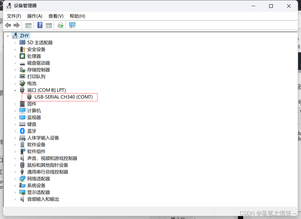
设置好串口号,波特率,数据位,停止位和校验位后打开串口
效果展示:
2.3串口控制LED亮灭
问题描述:STM32以查询方式接收上位机(win10)串口发来的数据,如果接收到“Y”则点亮链接到stm32上的一个LED灯;接收到“N”则熄灭LED灯。(设置波特率为9600,1位停止位,无校验位)
代码部分:
#include "stm32f10x.h"
#include "Delay.h"
int main(void)
{
	USART_InitTypeDef USART_InitStructure;
	RCC_APB2PeriphClockCmd(RCC_APB2Periph_USART1|RCC_APB2Periph_GPIOA,ENABLE);

	GPIO_InitTypeDef GPIO_InitStructure;

  GPIO_InitStructure.GPIO_Pin  =GPIO_Pin_9;
  GPIO_InitStructure.GPIO_Speed=GPIO_Speed_50MHz;
  GPIO_InitStructure.GPIO_Mode =GPIO_Mode_AF_PP;
  GPIO_Init(GPIOA,&GPIO_InitStructure );

  GPIO_InitStructure.GPIO_Pin = GPIO_Pin_10;
  GPIO_InitStructure.GPIO_Mode=GPIO_Mode_IN_FLOATING;
  GPIO_Init(GPIOA,&GPIO_InitStructure);

	GPIO_InitStructure.GPIO_Pin=GPIO_Pin_1;
	GPIO_InitStructure.GPIO_Mode=GPIO_Mode_Out_PP;
	GPIO_InitStructure.GPIO_Speed=GPIO_Speed_2MHz;
	GPIO_Init(GPIOA,&GPIO_InitStructure);

	USART_InitStructure.USART_BaudRate = 9600;
	USART_InitStructure.USART_WordLength= USART_WordLength_8b;
	USART_InitStructure.USART_StopBits= USART_StopBits_1;
	USART_InitStructure.USART_Parity = USART_Parity_No;
	USART_InitStructure.USART_Mode=USART_Mode_Rx;
	USART_InitStructure.USART_HardwareFlowControl=USART_HardwareFlowControl_None;
	USART_Init(USART1, &USART_InitStructure);
	USART_Cmd(USART1,ENABLE);

	GPIO_WriteBit(GPIOA,GPIO_Pin_1,0);

	while (1)
	{
		if(USART_GetFlagStatus(USART1, USART_IT_RXNE) == SET)
	{
   unsigned char a= USART_ReceiveData(USART1);
		if(a=='Y')
		{
			GPIO_WriteBit(GPIOA,GPIO_Pin_1,1);
		}
		else if(a=='N')
		{
			GPIO_WriteBit(GPIOA,GPIO_Pin_1,0);
		}
		else
		{

		}
	}
	}
}
接线图:
效果展示:
串口控制led亮灭
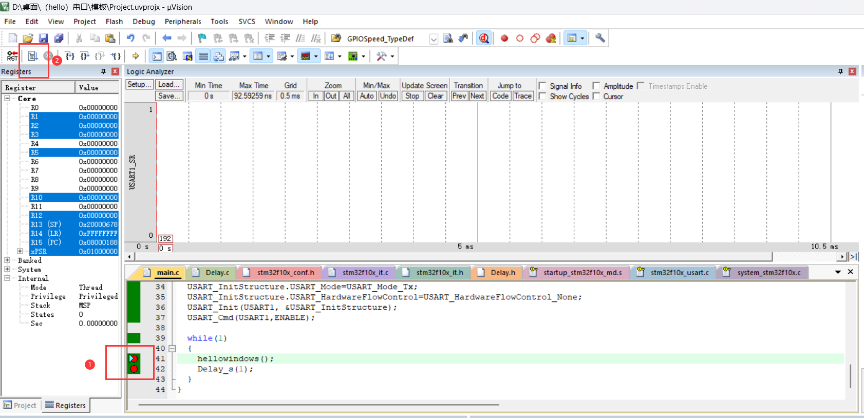
3.使用Keil的软件仿真逻辑分析仪分析波特率
问题:在没有示波器条件下,可以使用Keil的软件仿真逻辑分析仪功能观察管脚的时序波形,更方便动态跟踪调试和定位代码故障点。 请用此功能观察上题中的串口输出(PA9)和输入(PA10)、以及LED引脚(PA1)上的波形数据,并分析波特率是否正确。
对发送helloworld!的程序进行分析:插好stlink和串口模块
串口传输格式
●我们通常用的串口传输格式为:1bit起始位+8bit数据位+1bit停止位(无奇偶校验位),如下图所示:
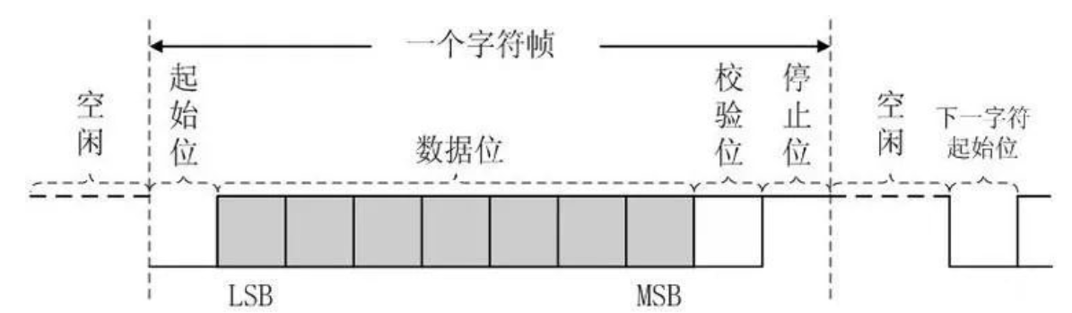
所以传输1Byte数据串口需要传输10bit数据
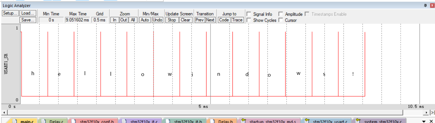
放大其中一个:
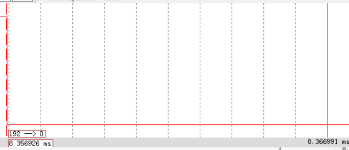
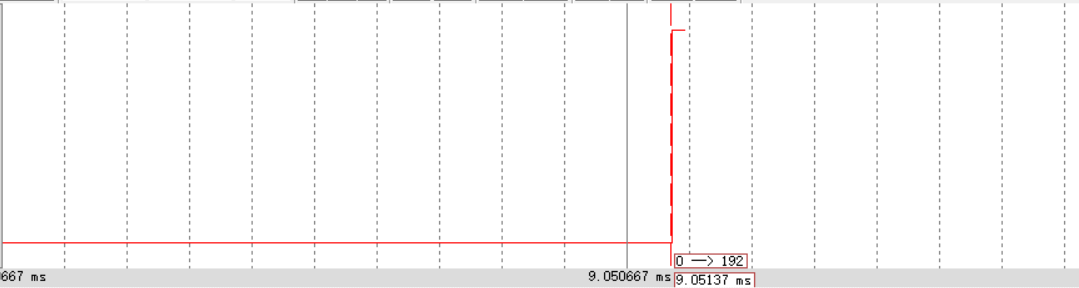
由上图:在9.05137-8.356923=0.69444ms内传输了10bit的数据
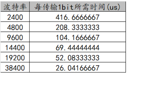
由上表:波特率为14400
总结
本次实验收获很大,学会了stm32串口通信的一些基本操作,但是在keil仿真计算波特率时,结果与我自己设置的波特率9600不吻合,但是在波形仿真的时候得出了每传输1bit所需的时间,为69.444微秒,即14400的波特率,与参考表高度吻合,我相信这不是巧合,应该波形仿真时系统默认的波特率为14400,只是我没有找到切换的方法,关于这点还希望大家多多指点。
参考资料:
STM32串口通信—串口的接收和发送详解_stm32串口的tx和rx-CSDN博客


 2355
2355

 被折叠的 条评论
为什么被折叠?
被折叠的 条评论
为什么被折叠?
 到【灌水乐园】发言


