


Arduino ATTiny85开发环境搭建及使用
ATTiny85开发板有以下两种:
第一种:可直接插入USB口:
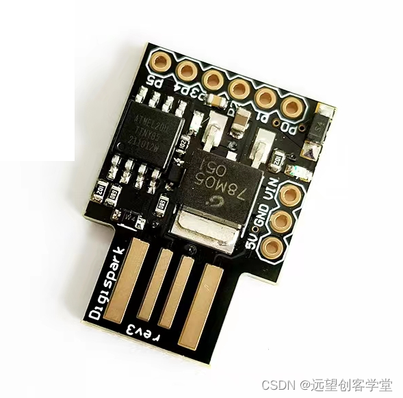
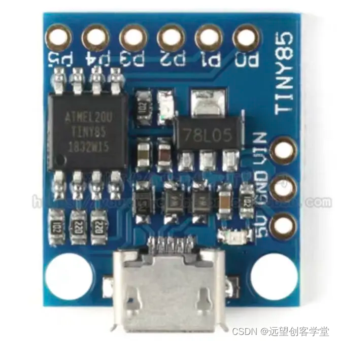
第二种:需要通过USB线来连接电脑:
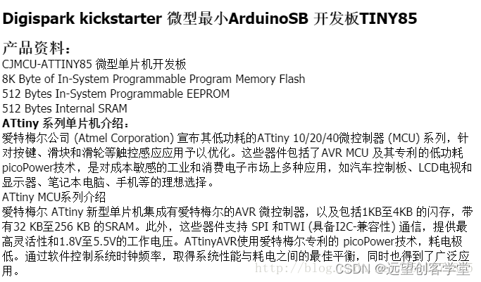
ATTiny85芯片介绍
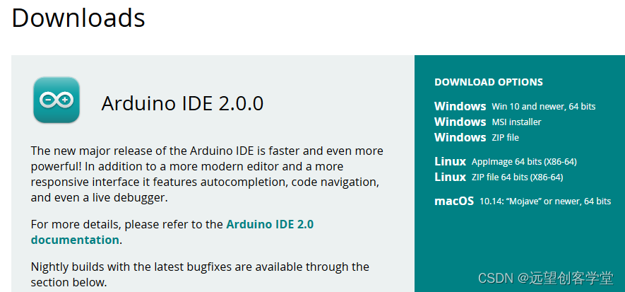
Arduino IDE下载及安装
在Arduino官网Software | Arduino下载最新版Arduino IDE并安装。
或使用安装版Arduino IDE。添加ATTiny85开发板库
在线安装:
Arduino IDE下文件-首选项-附加开发板管理器网址,添加
http://digistump.com/package_digistump_index.json
Arduino IDE下工具-开发板-开发板管理器,搜索找到Digistump AVR Boards项安装。
上面的方法可能会存在json无法解析的问题

如果无法安装请使用下面的离线安装方式。
离线安装:
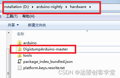
将“DigistumpArduino-master.zip”解压到Arduino IDE安装目录下的hardware文件夹下:
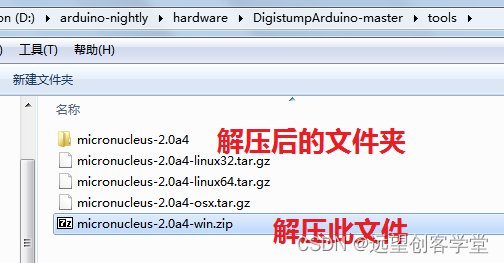
打开DigistumpArduino-master-tools文件夹,解压“micronucleus-2.0a4-win.zip”到当前目录
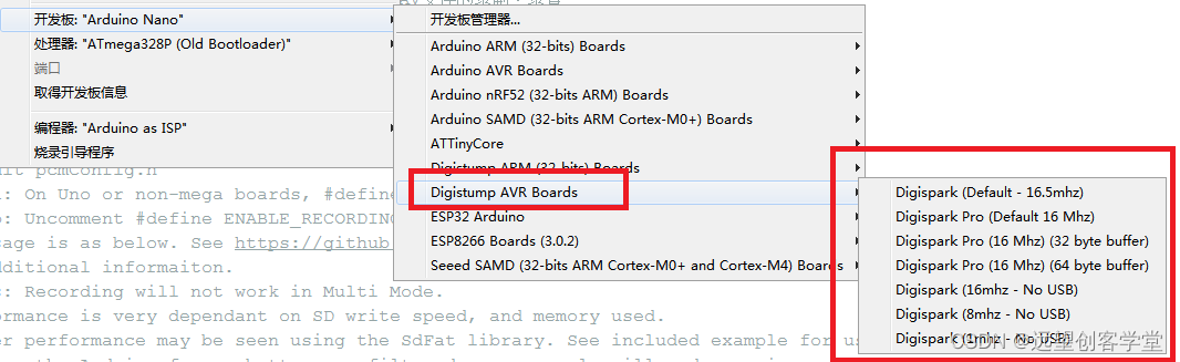
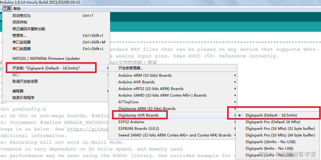
打开Arduino IDE 工具-开发板如下图所示,发现新增加的“Digistump AVR Boards”即可。
Arduino ATTiny85驱动安装
PC首次连接Arduino ATTiny85需安装USB驱动,注意如果你的电脑是第一次连接ATTiny85开发板则会听到USB设备连接的提示音,不过过了大概5秒左右就断开连接了,这是因为无法识别USB驱动造成的。如果不是第一次连接则可能再次插入ATTiny85时计算机就没有反应了。
在以下网址下载:
https://github.com/digistump/DigistumpArduino/releases/download/1.6.7/Digistump.Drivers.zip
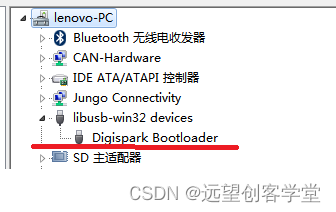
驱动正确安装后在设备管理器中显示如下:
程序编译及下载
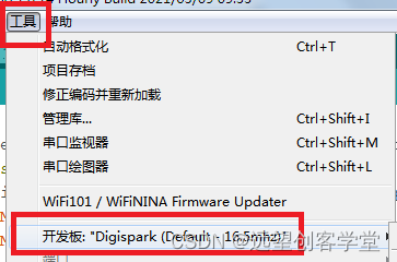
ATTiny85开发板选择“Digispark(Default – 16.5mhz)”
Arduino IDE 文件-示例下的例程是针对Digistump开发板的
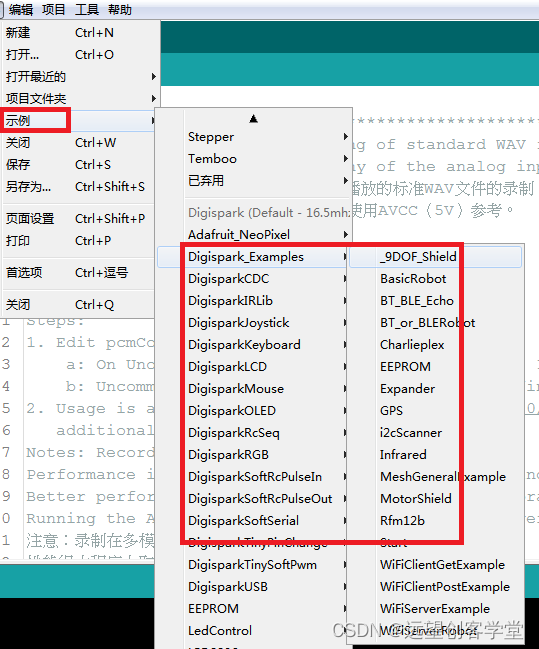
打开示例程序Start.ino,工具-开发板 选择Digispark(Default – 16.5mhz)
选择 项目-上传,注意此时不要连接ATTiny85开发板,出现下图所示的提示后再连接开发板
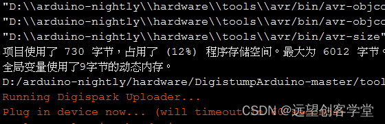
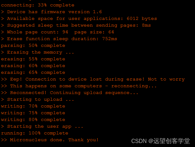
烧录成功的提示如下:
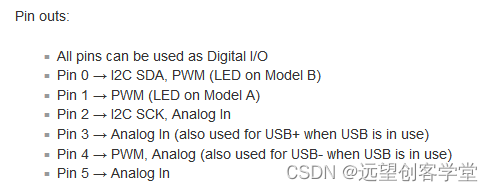
ATTiny85 Pinout
DigitalWrite:
void setup() {

    //All pins are capable of Digital output, though P5 is 3 V at HIGH instead of 5 V

    pinMode(0, OUTPUT); //0 is P0, 1 is P1, 2 is P2, etc. - unlike the analog inputs, for digital outputs the pin number matches.

}


void loop() {

    digitalWrite(0,HIGH); //Turn the pin HIGH (5 V)

    delay(1000);

    digitalWrite(0,LOW); //Turn the pin LOW (GND)

    delay(1000);

}
Digital Read:
注:ATtiny上的内部上拉电阻(在将管脚设置为输出后通过调用digitalWrite(0)打开,其中0是管脚编号)比Arduino上的要弱得多(约25千欧),因此板载LED会干扰它们。如果需要,可以使用其他端口。将电路更改为不需要内部上拉,大家可以加入远望创客学堂QQ群, 一起学习新知识。删除& —等特殊字符18&751-82&17。或切断LED轨迹。对于型号A,这将适用于型号B的P1,这将应用于P0。(型号标识)
int sensorValue = 0;

void setup() {

    //All pins are capable of digital input.

    pinMode(0, INPUT); //0 is P0, 1 is P1, 2 is P2, etc. - unlike the analog inputs, for digital inputs the pin number matches.

}


void loop() {

    sensorValue = digitalRead(1); //Returns HIGH or LOW (true or false / 1 or 0).

}
Analog Read:
int sensorValue = 0;
void setup() {

    //You need not set pin mode for analogRead - though if you have set the pin to

    //output and later want to read from it then you need to set pinMode(0,INPUT);

    //where 0 is the physical pin number not the analog input number.

    //

    //See below for the proper pinMode statement to go with each analog read.

}


void loop() {

    // The analog pins are referenced by their analog port number, not their pin

    //number and are as follows:

    sensorValue = analogRead(1); //Read P2

    //To set to input: pinMode(2, INPUT);

    //THIS IS P2, P2 is analog input 1, so when you are using analog read, you refer to it as 1.

    //sensorValue = analogRead(2); //Read P4

    //To set to input: pinMode(4, INPUT);

    //THIS IS P4, P4 is analog input 2, so when you are using analog read, you refer to it as 2.

    //sensorValue = analogRead(3); //Read P3

    //To set to input: pinMode(3, INPUT);

    //THIS IS P3, P3 is analog input 3, so when you are using analog read, you refer to it as 3.

    //sensorValue = analogRead(0); //Read P5

    //To set to input: pinMode(5, INPUT);

    //THIS IS P5, P5 is analog input 0, so when you are using analog read, you refer to it as 0.

}
Analog Write:
void setup() {

    //P0, P1, and P4 are capable of hardware PWM (analogWrite).

    pinMode(0, OUTPUT); //0 is P0, 1 is P1, 4 is P4 - unlike the analog inputs,

                        //for analog (PWM) outputs the pin number matches the port number.

}


void loop() {

    analogWrite(0,255); //Turn the pin on full (100%)

    delay(1000);

    analogWrite(0,128); //Turn the pin on half (50%)

    delay(1000);

    analogWrite(0,0);   //Turn the pin off (0%)

    delay(1000);

}
如果需要实现USB HID并且对管脚要求不多的场合可以考虑使用这个板子。


 2039
2039

 被折叠的 条评论
为什么被折叠?
被折叠的 条评论
为什么被折叠?
 到【灌水乐园】发言


