


测速模块
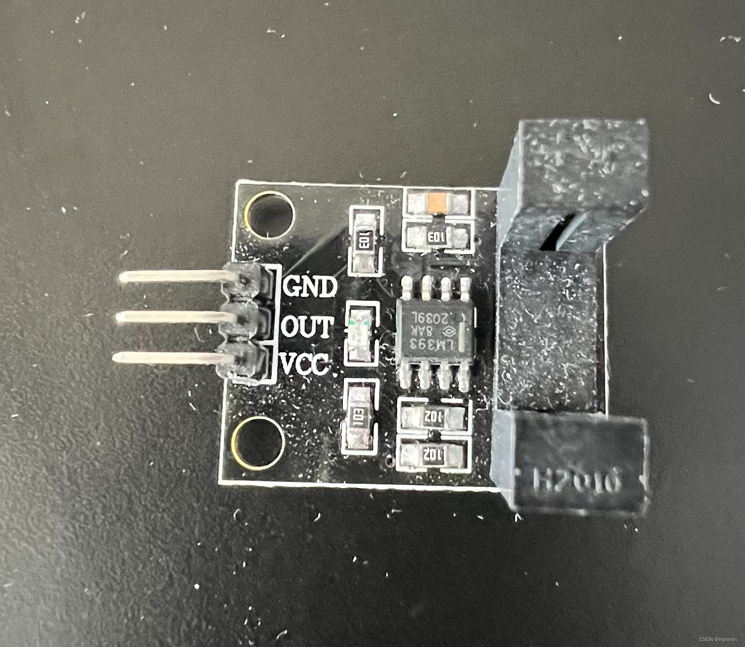
测速模块的原理很简单,概况一下就是:有遮挡的时候会输出高电平;没遮挡的时候会输出低电平,根据之前小车安装的测速片,结合这个测速模块,通过计算高低电平变化的频率,就可以计算出速度!
测速的具体计算
根据上面所说,目的就是根据高低电平来计算出速度:
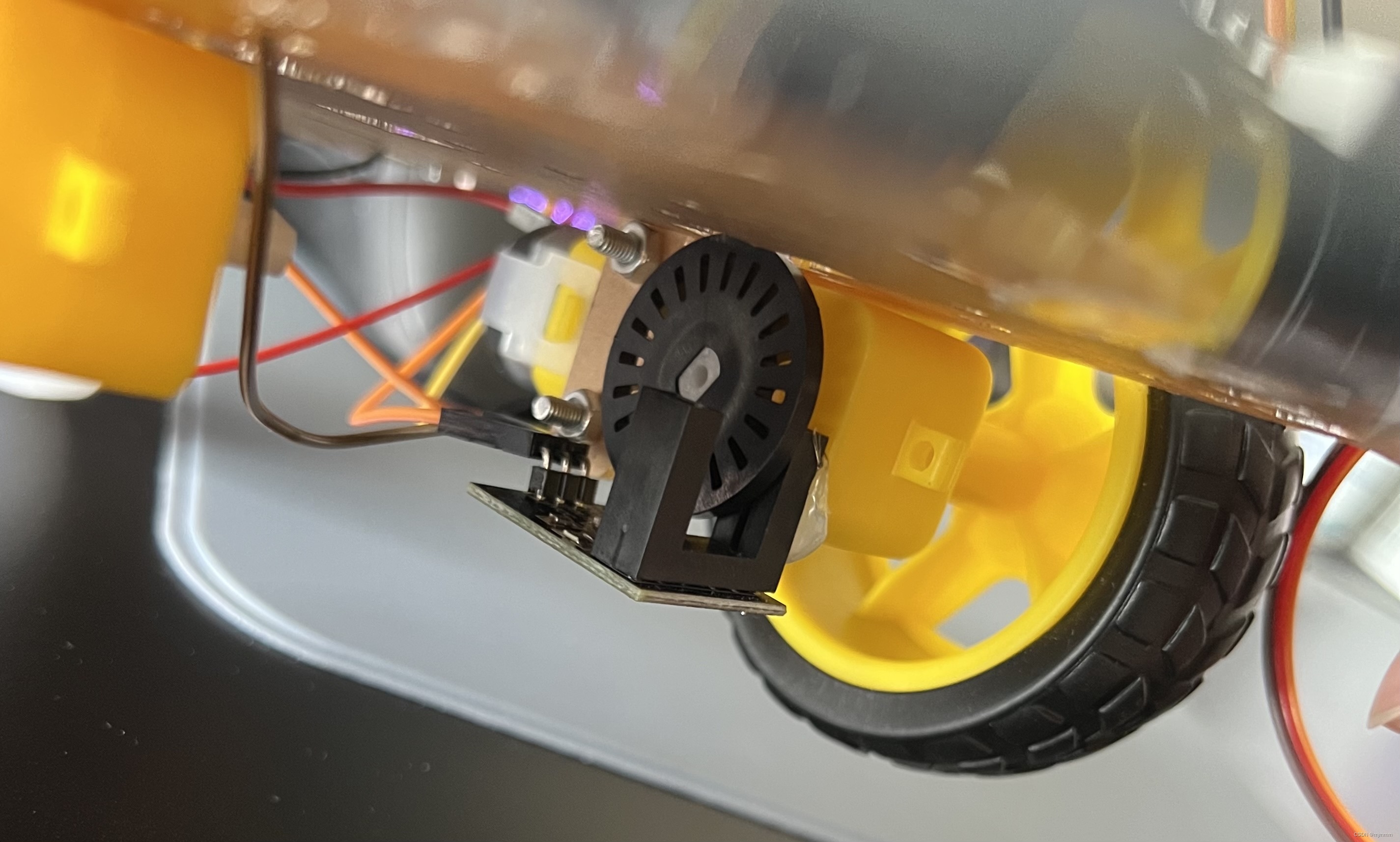
已知轮子走一圈,经过一个周长 C = 2 X 3.14 X 半径 = 3.14 X 直径(6.5cm),对应固定在电机轴上的码盘也转了一圈,而码盘有20个格子,每经过一个格子,就会经历一次不遮挡(格子的空袭)和一次遮挡(格子空隙之后到下一个格子之前的实心材料);即每经过一个格子就会有一次低电平和高电平,这就是一个脉冲,而走完20个格子就轮子就会转一圈,因此走过一个格子经过的距离就是C/20 = 3.14*6.5/20 = 1.0205 CM 约等于 1CM。
此时如果将定时器设计成1S,然后统计1S的脉冲数,那检测到了Y个脉冲就是YCM,对应的速度就是Y cm/s
模块组装
将模块粘在测速轮的两边,将VCC和GND接到单片机引出的面包板的正负极,并将OUT口接到P2.1 (后改为P3.2,见之后的说明)
代码实现
UART.c:
#include "reg52.h"
#include "delay.h"
#include "motor.h"
#include <string.h>

sfr AUXR = 0x8E; //配置了这句话,才可以在UART的初始化里写AUXR寄存器,原因见STC89系列的手册

void UartInit(void)		//9600bps@11.0592MHz
{
	PCON &= 0x7F;		//波特率不倍速
	SCON = 0x50;		//8位数据,可变波特率
	AUXR &= 0xBF;		//定时器1时钟为Fosc/12,即12T
	AUXR &= 0xFE;		//串口1选择定时器1为波特率发生器
	TMOD &= 0x0F;		//清除定时器1模式位
	TMOD |= 0x20;		//设定定时器1为8位自动重装方式
	TL1 = 0xFD;		//设定定时初值
	TH1 = 0xFD;		//设定定时器重装值
	ET1 = 0;		//禁止定时器1中断
	TR1 = 1;		//启动定时器1
}

void printSTR(char *msg)
{
	while(*msg != '\0'){
		SBUF = *msg; //往发送缓冲器里写入数据,就完成了数据的发送
		while(TI == 0); //只有当TI为1时,才往下走,根据手册,TI只有在发送完8位数据后才会硬件自动置1
		TI = 0;
		msg++;
	}

}

void printChar(char msg)
{
		SBUF = msg; //往发送缓冲器里写入数据,就完成了数据的发送
		while(TI == 0); //只有当TI为1时,才往下走,根据手册,TI只有在发送完8位数据后才会硬件自动置1
		TI = 0;
}
speed.c:
#include "reg52.h"
#include "UART.h"

sfr AUXR = 0x8E; //配置了这句话,才可以在UART的初始化里写AUXR寄存器,原因见STC89系列的手册

sbit OUT = P2^1;
int cnt_timer = 0;
int cnt_pulse = 0;
int speed = 0;

void Timer0Init(void)
{
	AUXR &= 0x7F;		//定时器时钟12T模式
	TMOD &= 0xF0;		//设置定时器模式
	TMOD |= 0x01;		//设置定时器模式
	TL0 = 0x00;		//设置定时初值
	TH0 = 0x4C;		//设置定时初值 //50ms
	TF0 = 0;		//清除TF0标志
	TR0 = 1;		//定时器0开始计时

	ET0 = 1;
	EA = 1;   //打开中断!
}

//timer0的中断处理程序 //中断程序一般写在main函数的后面 //定时器0溢出时将触发这个中断函数
void speed_inter() interrupt 1
{
	cnt_timer++;
	TL0 = 0x00;		//设置定时初值
	TH0 = 0x4C;		//设置定时初值 //50ms


	if(cnt_timer == 20){//经过(20*50毫秒 =)1秒
		cnt_timer = 0;
		speed = cnt_pulse;
		printSTR("speed = ");

		if((speed/10) == 0){//说明speed是个位数
			printChar(speed + 0x30);
		}else{//说明speed是两位数
			printChar(speed/10%10 + 0x30);//“速度的十位”显示字符型数字
			printChar(speed/1%10 + 0x30);//“速度的个位”显示字符型数字
		}

		printSTR("cm/s\r\n");
		cnt_pulse = 0;
	}

}

void pulse_detect()
{
	while(OUT == 1);//等待OUT变成低电平,即等待一次不遮挡
	while(OUT == 0);//等待OUT变成高电平,即等待一次遮挡
	cnt_pulse++; //此时经过一个脉冲

}
main.c
#include "reg52.h"
#include "intrins.h" //这个库加了,delay函数里面的nop()才不会报错
#include "motor.h"
#include "delay.h"
#include "speed.h"
#include "UART.h"


void main()
{
	Timer0Init();
	UartInit();

	while(1){
		move_forward();
		pulse_detect();
	}

}
实现效果
由于使用了串口来不断发送速度信息,因此可以使用蓝牙模块在手机上接收:
一些问题
以上代码虽然可以实现期望的效果,但是也有一些问题,就是由于“paulse_detect"函数使用了两个while(),会导致一旦调用了这个函数,那么除了中断之外的方法都无法让程序执行其他功能了,在这个单纯实现测速的代码中这样做没有问题,但是如果想要在测速的基础上再实现一些其他的功能,那“paulse_detect"函数的写法就不利于功能的扩展了....
解决办法就是将测速传感器的脉冲检测的OUT口也配置成一个中断,即使用P3.2口的外部中断(但是P3.2之前用于给电机供电,所以别忘记还需要修改一下电机部分的sbit定义!!),这样既可以保留测速的功能,也不会影响main函数之后可能进行的其他操作。
同时需要注意,配置外部中断时,应该配置成下降沿触发而不是低电平触发:

也就是IT0 = 1 !
同时,对于speed的显示,刚刚对于每一位的提取再转化为字符的行为很麻烦,可以使用sprintf(speed_real,"speed: %d cm/s\r\n",speed); 来直接构建字符串,但是记得提前定义一个char speed_real[24],并添加stdio.h的库!
接下来看看修改后的代码:
motor.c中的新定义:
sbit B_1A_le = P3^6;//LEFT WHEELspeed.c:
#include "reg52.h"
#include "UART.h"
#include "stdio.h"

sfr AUXR = 0x8E; //配置了这句话,才可以在UART的初始化里写AUXR寄存器,原因见STC89系列的手册

sbit OUT = P3^2;
int cnt_timer = 0;
int cnt_pulse = 0;
int speed = 0;
char speed_real[24];

void Timer0Init(void)
{
	AUXR &= 0x7F;		//定时器时钟12T模式
	TMOD &= 0xF0;		//设置定时器模式
	TMOD |= 0x01;		//设置定时器模式
	TL0 = 0x00;		//设置定时初值
	TH0 = 0x4C;		//设置定时初值 //50ms
	TF0 = 0;		//清除TF0标志
	TR0 = 1;		//定时器0开始计时

	ET0 = 1;
	EA = 1;   //打开中断!

}

void EX0_Init()
{
	EX0 = 1; //打开外部中断
	IT0 = 1;  //不是低电平触发,而是下降沿触发!!!
}


//timer0的中断处理程序 //中断程序一般写在main函数的后面 //定时器0溢出时将触发这个中断函数
void speed_inter() interrupt 1
{
	cnt_timer++;
	TL0 = 0x00;		//设置定时初值
	TH0 = 0x4C;		//设置定时初值 //50ms


	if(cnt_timer == 20){//经过(20*50毫秒 =)1秒
		cnt_timer = 0;
		speed = cnt_pulse;

		sprintf(speed_real,"speed: %d cm/s\r\n",speed); //构建字符串
		printSTR(speed_real);

		cnt_pulse = 0;
	}

}


void pulse_Inter() interrupt 0 //外部中断0,即P3.2口变低电平时会自动触发这个中断处理程序,即触发一次不遮挡就会进入中断
{
	cnt_pulse++; //此时经过一个脉冲
}
UART.c:
#include "reg52.h"
#include "delay.h"
#include "motor.h"
#include <string.h>

sfr AUXR = 0x8E; //配置了这句话,才可以在UART的初始化里写AUXR寄存器,原因见STC89系列的手册
static int i = 0; //此时这句命令只会被执行一次。避免每次发生中断i都会清0
char cmd[12];

void UartInit(void)		//9600bps@11.0592MHz
{
	PCON &= 0x7F;		//波特率不倍速
	SCON = 0x50;		//8位数据,可变波特率
	AUXR &= 0xBF;		//定时器1时钟为Fosc/12,即12T
	AUXR &= 0xFE;		//串口1选择定时器1为波特率发生器
	TMOD &= 0x0F;		//清除定时器1模式位
	TMOD |= 0x20;		//设定定时器1为8位自动重装方式
	TL1 = 0xFD;		//设定定时初值
	TH1 = 0xFD;		//设定定时器重装值
	ET1 = 0;		//禁止定时器1中断
	TR1 = 1;		//启动定时器1
}

void printSTR(char *msg)
{
	while(*msg != '\0'){
		SBUF = *msg; //往发送缓冲器里写入数据,就完成了数据的发送
		while(TI == 0); //只有当TI为1时,才往下走,根据手册,TI只有在发送完8位数据后才会硬件自动置1
		TI = 0;
		msg++;
	}

}
main.c:
#include "reg52.h"
#include "intrins.h" //这个库加了,delay函数里面的nop()才不会报错
#include "motor.h"
#include "delay.h"
#include "speed.h"
#include "UART.h"


void main()
{
	Timer0Init();
	EX0_Init();
	UartInit();

	while(1){
		move_forward();
	}

}
又一些问题
我发现测速模块显示的速度有时候很诡异,显示200cm/s左右,但是实际必然没有那么快,似乎只有拍摄上面GIF动图时的速度比较正常,但是我反复查看代码感觉逻辑也没有什么问题,所以我猜测也是应该硬件的原因,我的测速模块粘的位置可能欠佳,没法准确的捕捉电机轴上速度轮的间隙导致的 = =.....
测速OLED显示
在速度可以得出并通过串口发送之后,就可以尝试将速度显示在OLED屏幕上,OLED的显示之前就学习过,所以无非就是代码的移植。
首先,再次使用万能的星巴克咖啡杯和热熔胶浅浅固定一下OLED屏幕:

但是有一个问题,我希望在OLED上显示的是 speed = xxx cm/s,而根据之前学习的知识,每一个字符都需要去字模软件中去转换,十分麻烦,在购买OLED的时候,厂商一般会提供一个h文件,和利用这个文件来显示字符的函数,因此之间将这个h文件 include进来并使用预设的函数就可以方便的调用!
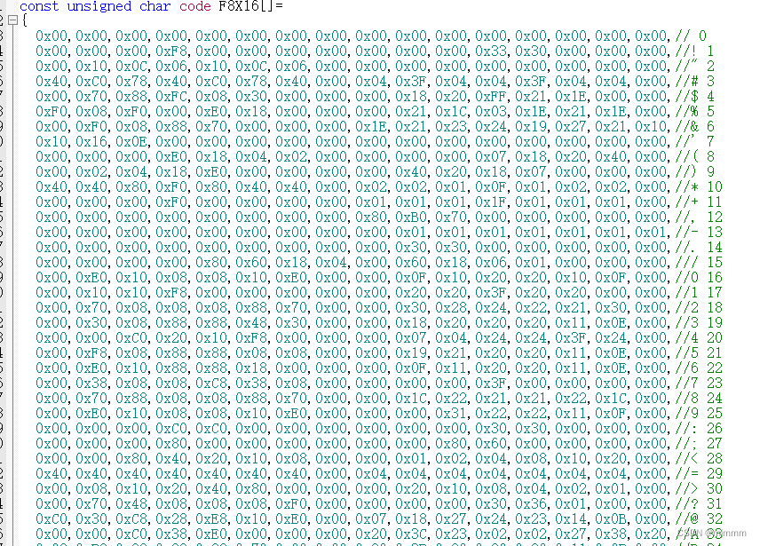
利用这些,可以轻松写出OLED.c部分的代码:
#include "reg52.h"
#include "intrins.h" //这个库加了,delay函数里面的nop()才不会报错
#include <string.h>
#include "OLEDfont.h"
sfr AUXR = 0x8E; //配置了这句话,才可以在UART的初始化里写AUXR寄存器,原因见STC89系列的手册
sbit SCL = P1^3;
sbit SDA = P1^2;
void IIC_start()
{
SDA = 0;
SCL = 1;
SDA = 1;
_nop_(); //约5微妙
SDA = 0;
_nop_();
SCL = 0;
}
void IIC_stop()
{
SCL = 0;
SCL = 1;
SDA = 0;
_nop_();
SDA = 1;
_nop_();
SDA = 0;
}
char IIC_ACK()
{
char flag;
SDA = 1;//在脉冲9释放数据线
_nop_();
SCL = 1;
_nop_();
flag = SDA;
_nop_();
SCL = 0;
//_nop_();
return flag;
}
void IIC_sendByte(char sdata) //data直接定义为char的好处是char就是1个byte(8个bit)
{
int i;
for(i = 0; i < 8; i++){
SCL = 0; //拉低,让SDA准备数据
SDA = sdata & 0x80; //与上“1000 0000”,即只有最高位保留,其他全部清0
_nop_();//给数据建立一个时间
SCL = 1; //拉高,形成脉冲开始传输,此时SDA不能变
_nop_();//发送中
SCL = 0;//重新拉低
_nop_();
sdata = sdata << 1; //发完1个bit左移一位
}
}
void OLED_writecmd(char cmd)
{
IIC_start();
IIC_sendByte(0x78);
IIC_ACK();
IIC_sendByte(0x00);
IIC_ACK();
IIC_sendByte(cmd);
IIC_ACK();
IIC_stop();
}
void OLED_writedata(char wdata)
{
IIC_start();
IIC_sendByte(0x78);
IIC_ACK();
IIC_sendByte(0x40);
IIC_ACK();
IIC_sendByte(wdata);
IIC_ACK();
IIC_stop();
}
void Oled_Init()
{
OLED_writecmd(0xAE);//--display off
OLED_writecmd(0x00);//---set low column address
OLED_writecmd(0x10);//---set high column address
OLED_writecmd(0x40);//--set start line address
OLED_writecmd(0xB0);//--set page address
OLED_writecmd(0x81); // contract control
OLED_writecmd(0xFF);//--128
OLED_writecmd(0xA1);//set segment remap
OLED_writecmd(0xA6);//--normal / reverse
OLED_writecmd(0xA8);//--set multiplex ratio(1 to 64)
OLED_writecmd(0x3F);//--1/32 duty
OLED_writecmd(0xC8);//Com scan direction
OLED_writecmd(0xD3);//-set display offset
OLED_writecmd(0x00);//
OLED_writecmd(0xD5);//set osc division
OLED_writecmd(0x80);//
OLED_writecmd(0xD8);//set area color mode off
OLED_writecmd(0x05);//
OLED_writecmd(0xD9);//Set Pre-Charge Period
OLED_writecmd(0xF1);//
OLED_writecmd(0xDA);//set com pin configuartion
OLED_writecmd(0x12);//
OLED_writecmd(0xDB);//set Vcomh
OLED_writecmd(0x30);//
OLED_writecmd(0x8D);//set charge pump enable
OLED_writecmd(0x14);//
OLED_writecmd(0xAF);//--turn on oled panel
}
void Oled_Clear()
{
int i;
int j;
for(i = 0; i<8; i++){
OLED_writecmd(0xB0 + i);//依次选择每一页
OLED_writecmd(0x00);//选择0列
OLED_writecmd(0x10);//选择0列
for(j = 0; j<128; j++){
OLED_writedata(0x00);//由于地址会自动偏移,所以只要重复写128次全0,就可以清一个PAGE
}
}
}
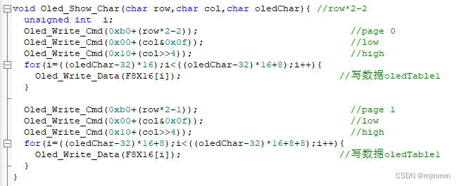
void Oled_Show_Char(char row,char col,char oledChar){ //row*2-2
unsigned int i;
OLED_writecmd(0xb0+(row*2-2)); //page 0
OLED_writecmd(0x00+(col&0x0f)); //low
OLED_writecmd(0x10+(col>>4)); //high
for(i=((oledChar-32)*16);i<((oledChar-32)*16+8);i++){
OLED_writedata(F8X16[i]); //写数据oledTable1
}
OLED_writecmd(0xb0+(row*2-1)); //page 1
OLED_writecmd(0x00+(col&0x0f)); //low
OLED_writecmd(0x10+(col>>4)); //high
for(i=((oledChar-32)*16+8);i<((oledChar-32)*16+8+8);i++){
OLED_writedata(F8X16[i]); //写数据oledTable1
}
}
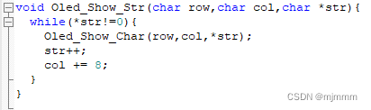
void Oled_Show_Str(char row,char col,char *str){
while(*str!=0){
Oled_Show_Char(row,col,*str);
str++;
col += 8;
}
}speed.c:
#include "reg52.h"
#include "UART.h"
#include "stdio.h"

sfr AUXR = 0x8E; //配置了这句话,才可以在UART的初始化里写AUXR寄存器,原因见STC89系列的手册

sbit OUT = P3^2;
int cnt_timer = 0;
int cnt_pulse = 0;
int speed = 0;
char speed_real[24];


void Timer0Init(void)
{
	AUXR &= 0x7F;		//定时器时钟12T模式
	TMOD &= 0xF0;		//设置定时器模式
	TMOD |= 0x01;		//设置定时器模式
	TL0 = 0x00;		//设置定时初值
	TH0 = 0x4C;		//设置定时初值 //50ms
	TF0 = 0;		//清除TF0标志
	TR0 = 1;		//定时器0开始计时

	ET0 = 1;
	EA = 1;   //打开中断!

}

void EX0_Init()
{
	EX0 = 1; //打开外部中断
	IT0 = 1;  //不是低电平触发,而是下降沿触发!!!
}


//timer0的中断处理程序 //中断程序一般写在main函数的后面 //定时器0溢出时将触发这个中断函数
void speed_inter() interrupt 1
{
	cnt_timer++;
	TL0 = 0x00;		//设置定时初值
	TH0 = 0x4C;		//设置定时初值 //50ms


	if(cnt_timer == 20){//经过(20*50毫秒 =)1秒
		cnt_timer = 0;
		speed = cnt_pulse;

		sprintf(speed_real,"speed: %d cm/s",speed); //构建字符串
		printSTR(speed_real);
		printSTR("\r\n");

		cnt_pulse = 0;
	}

}


void pulse_Inter() interrupt 0 //外部中断0,即P3.2口变低电平时会自动触发这个中断处理程序,即触发一次不遮挡就会进入中断
{
	cnt_pulse++; //此时经过一个脉冲
}
main.c:
#include "reg52.h"
#include "intrins.h" //这个库加了,delay函数里面的nop()才不会报错
#include "motor.h"
#include "delay.h"
#include "speed.h"
#include "UART.h"
#include "OLED.h"

extern char speed_real[24];

void main()
{
	Timer0Init();
	EX0_Init();
	UartInit();
	ES = 1;
	EA = 1; //打开中断!

	Oled_Init();
	Oled_Clear();
	OLED_writecmd(0x20);//页寻址模式
	OLED_writecmd(0x02);//页寻址模式

	while(1){
		Oled_Show_Str(2,2,speed_real);
		Delay1000ms();
	}

}
实现效果:
在手机蓝牙中发送“M1”指令,小车轮子开始转动,此时速度信息同时通过手机蓝牙和OLED显示:
(虽然速度的值不太对就是了...)


 653
653


 被折叠的 条评论
为什么被折叠?
被折叠的 条评论
为什么被折叠?
 到【灌水乐园】发言


