


- boot0=1, boot1=1
- 函数如下
int main(void)
{
  RCC->APB2ENR |= 0x00000010;  // I/O port C clock enabled
  GPIOC->CRH   &= 0xFF0FFFFF;  // set general purpose output mode for LEDs
  GPIOC->CRH   |= 0x00100000;  // PC13 pull-push,
  //GPIOC->BSRR   = 0x20000000;  // LEDs on
  //GPIOC->BSRR   = 0x00002000;  // LEDs off

	while(1) {
		GPIOC->BSRR = 0x20000000;  //set high level
		DelayMicroSeconds(2000000); //On LED, delay 2seconds

		GPIOC->BSRR = 0x00002000; // set low level
		DelayMicroSeconds(2000000); //off LED, 2seconds

	}
}
- 按reset就可以看到LED1闪烁了。
程序讲解:
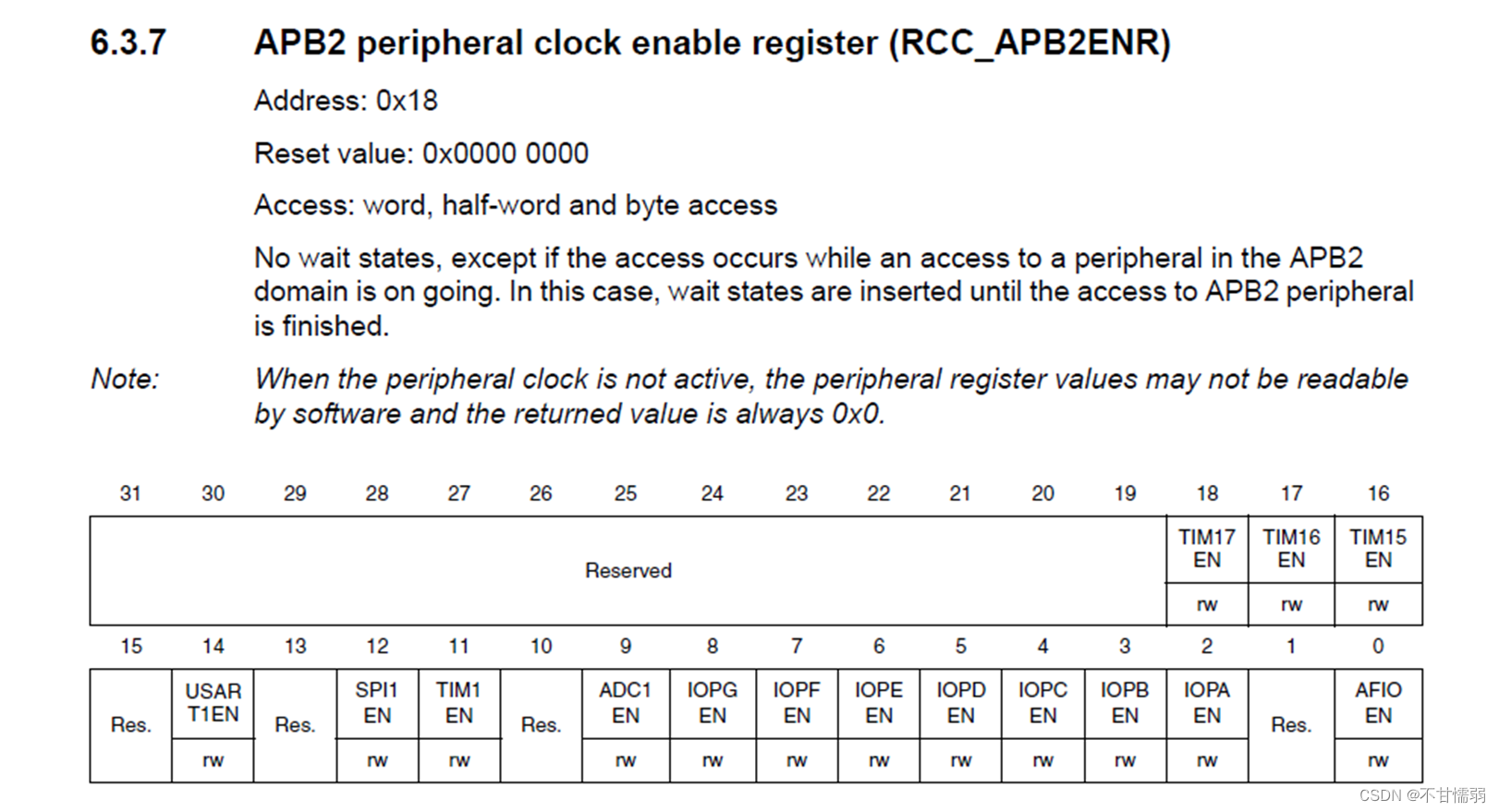
RCC->APB2ENR
RCC->APB2ENR |= 0x00000010; // I/O port C clock enabled
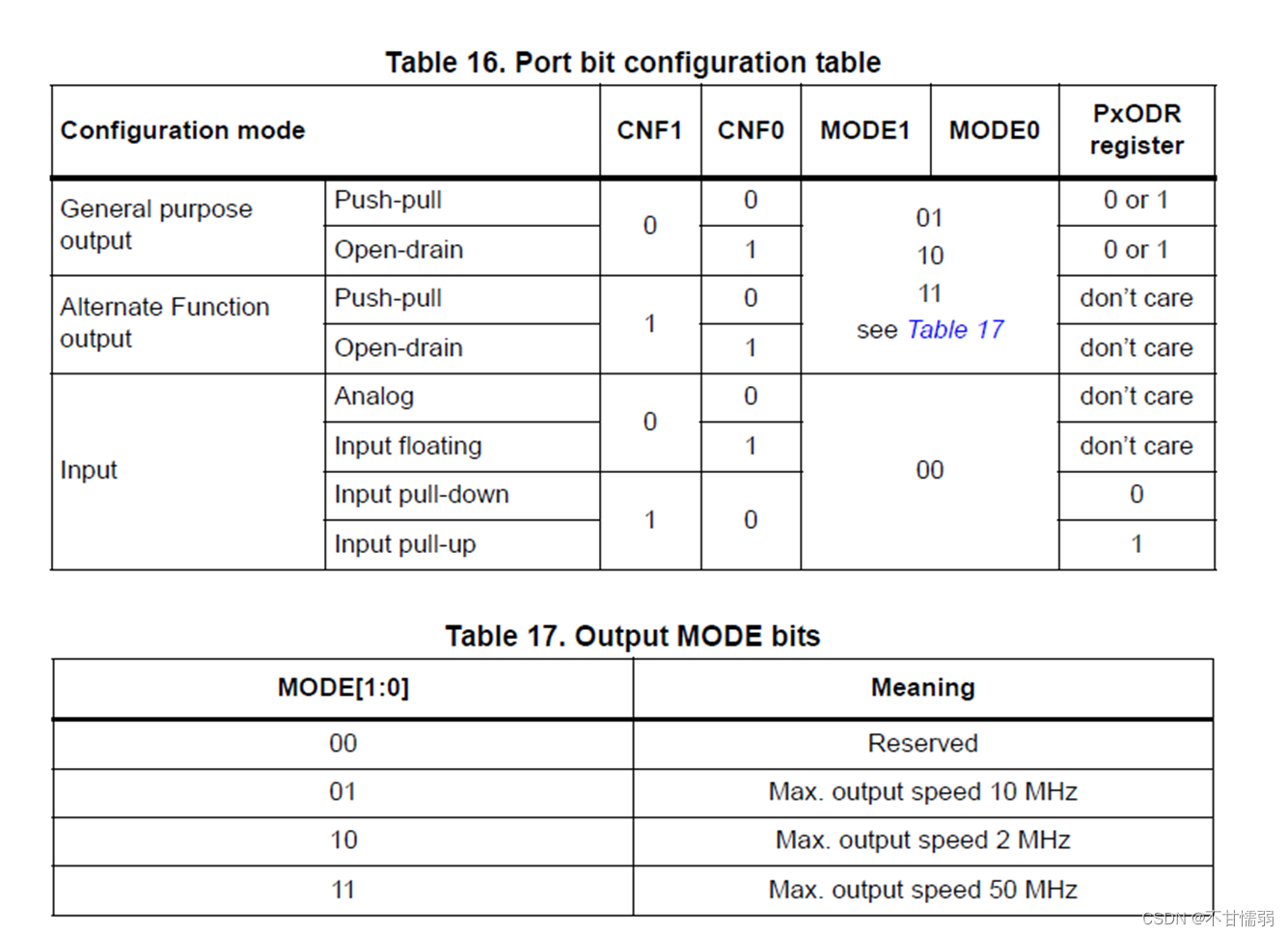
GPIOx->CRH
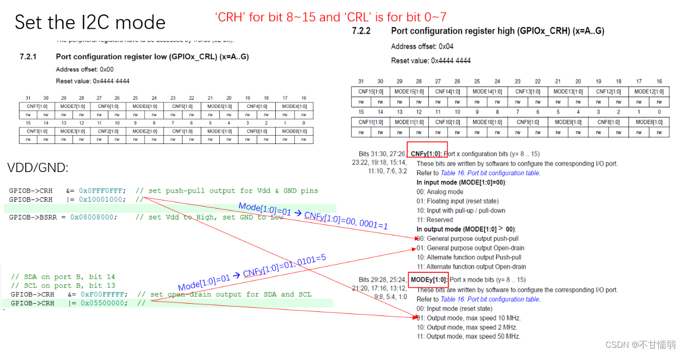
// SDA on port B, bit 14
#define SDA_LOW()  (GPIOB->BSRR = 0x40000000) // set SDA to low
#define SDA_OPEN() (GPIOB->BSRR = 0x00004000) // set SDA to open-drain
#define SDA_READ   (GPIOB->IDR  & 0x4000)     // read SDA


// SCL on port B, bit 13              /* -- adapt the defines for your uC -- */
#define SCL_LOW()  (GPIOB->BSRR = 0x20000000) // set SCL to low
#define SCL_OPEN() (GPIOB->BSRR = 0x00002000) // set SCL to open-drain
#define SCL_READ   (GPIOB->IDR  & 0x2000)     // read SCL
GPIOx->BSRR
GPIOC->BSRR = 0x20000000; // LEDs on
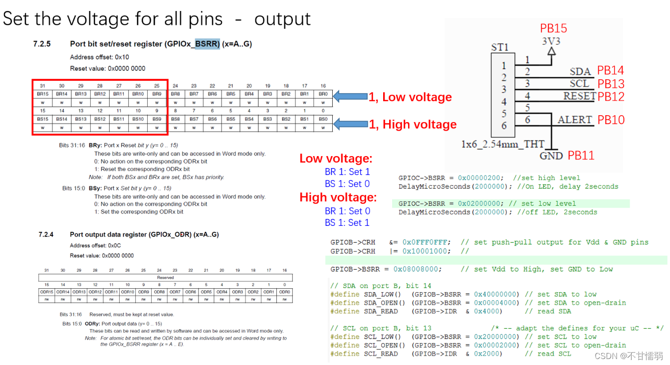
  RCC->APB2ENR |= 0x00000008;  // I/O port B clock enabled

  GPIOB->CRH   &= 0x0FF0FFFF;  // set push-pull output for Vdd & GND pins
  GPIOB->CRH   |= 0x10010000;  // set mode for PB12/PB15

  GPIOB->BSRR = 0x10008000;     //set Vdd to High, set GND to Low- GND PB12, VDD PB15, BS-high, BR-low


 1580
1580


 被折叠的 条评论
为什么被折叠?
被折叠的 条评论
为什么被折叠?
 到【灌水乐园】发言


