


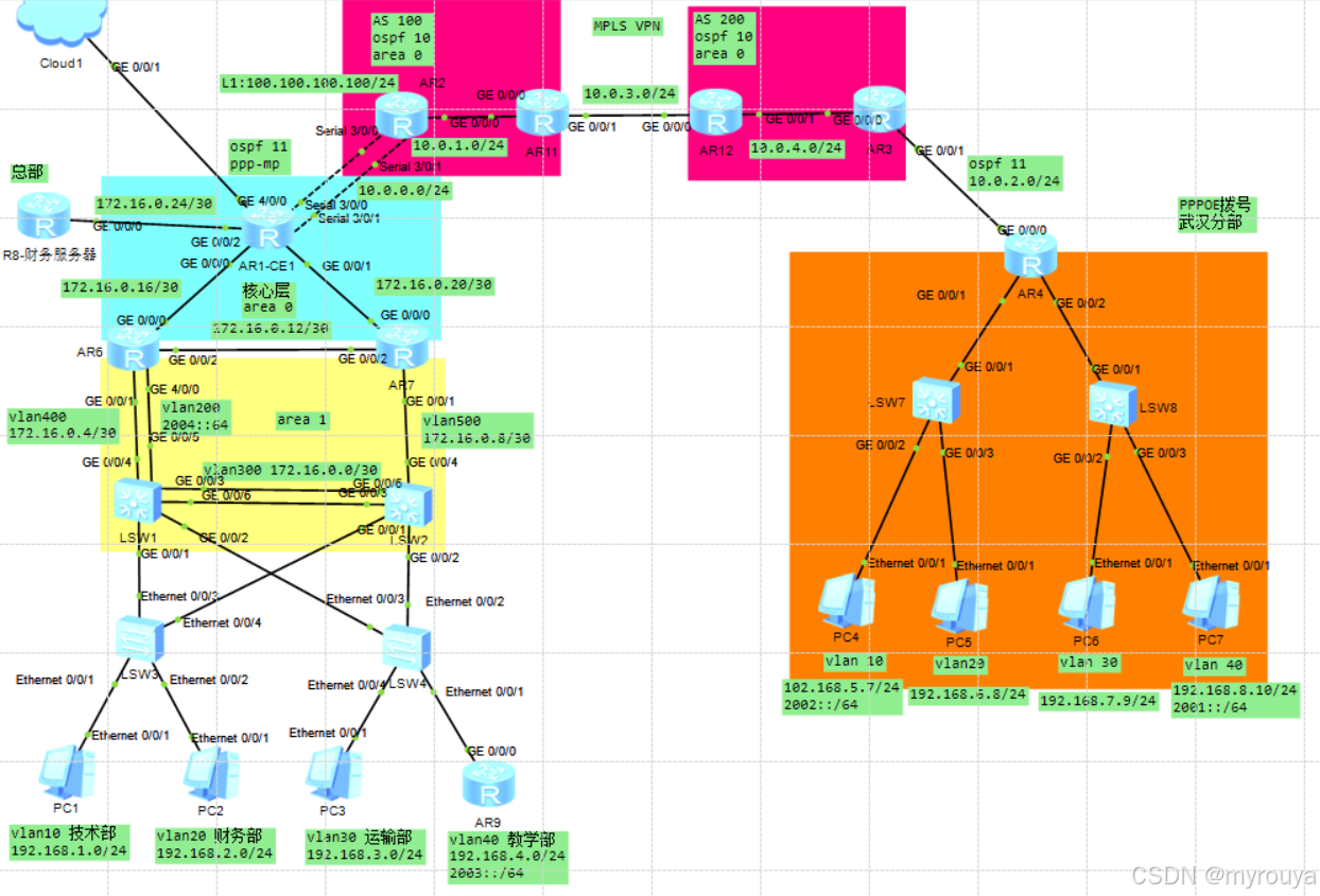
一、实验拓扑:
这是我的全部拓扑图,本篇文章只讲解MPLS VPL(optionA)
二、实验要求(这里我只写了公网要求)
(1)在AS 200内部,使用OSPF 10搞通建邻地址的基础上,再使用BGP协议搞通公网,AS100、AS 200用于IBGP建邻的环口地址格式:根据公网设备编号X.X.X.X/32,例如R1的建邻地址为1.1.1.1/32,EBGP邻居使用物理口建邻
(2)使用MPLS VPN,搞通两端私网,不需要传递两端网络的所有私网网段,要求只传递两端192开头的业务网段
三、实验思路
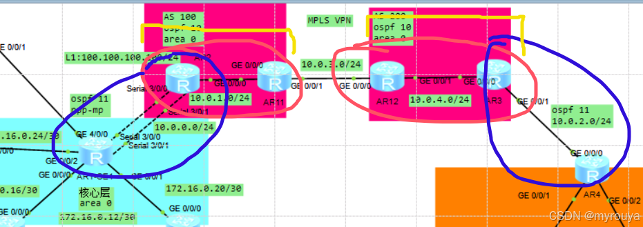
蓝色部分是OSPF11
红色部分是OSPF10以及BGP100 和200(AR2和AR11建立IBGP邻居,反之,AR11和AR12之间建立EBGP邻居,和AR3建立IBGP邻居)
黄色部分是两个MPLS VPN(因为这是两个AS(可以理解为两个运营商),所以不能用一个VPN,得用两个)
!!!废话不多说看步骤 !!!
四、实验步骤
AR1:(私网部分我做了NAT,与公网连接我做了聚合Mp-group0/0/0)
interface Mp-group0/0/0
ip address 10.0.0.1 255.255.255.0
nat outbound 2000
#
interface Serial3/0/0
link-protocol ppp
ppp mp Mp-group 0/0/0
#
interface Serial3/0/1
link-protocol ppp
ppp mp Mp-group 0/0/0
OSPF部分:
ospf 1 router-id 1.1.1.1
default-route-advertise
area 0.0.0.0
network 172.16.0.18 0.0.0.0
network 172.16.0.22 0.0.0.0
network 172.16.0.26 0.0.0.0
#
ospf 11
area 0.0.0.0
network 0.0.0.0 255.255.255.255
network 10.0.0.1 0.0.0.0
AR2:(需要在OSPF11和BGP双向引入)
OSPF部分:OSPF10是私网部分可以不管
ospf 10
area 0.0.0.0
network 2.2.2.2 0.0.0.0
network 10.0.1.2 0.0.0.0
network 100.100.100.100 0.0.0.0
#
ospf 11 router-id 2.2.2.2 vpn-instance a
import-route bgp
area 0.0.0.0
network 10.0.0.2 0.0.0.0
BGP部分:
bgp 100
peer 11.11.11.11 as-number 100
peer 11.11.11.11 connect-interface LoopBack1
#
ipv4-family unicast
undo synchronization
peer 11.11.11.11 enable
#
ipv4-family vpnv4
policy vpn-target
peer 11.11.11.11 enable
#
ipv4-family vpn-instance a
import-route ospf 11
VPN实例部分:(routerID我同一个AS用的一样的,这个不影响,但一个设备的出口VPN-target要和另一个设备的入口一样,我这里全都用的一样所以就避开的这个问题)
ip vpn-instance a
ipv4-family
route-distinguisher 100:1
vpn-target 100:1 export-extcommunity
vpn-target 100:1 import-extcommunity
聚合口部分:
注意:
1.因为这是是入口需要绑定VPN实例
2.输入完绑定实例过后IP地址会失效,记得重新配置一遍ID地址
interface Mp-group0/0/0
##绑定实例
ip binding vpn-instance a
ip address 10.0.0.2 255.255.255.0
#
interface Serial3/0/0
link-protocol ppp
ppp mp Mp-group 0/0/0
#
interface Serial3/0/1
link-protocol ppp
ppp mp Mp-group 0/0/0
配置设备lsr-ID
mpls lsr-id 2.2.2.2
mpls
#
mpls ldp
右边接口:(需要运行传输MPLS报文)
interface GigabitEthernet0/0/0
ip address 10.0.1.2 255.255.255.0
mpls
mpls ldp
AR11:
VPN实例部分:
ip vpn-instance a
ipv4-family
route-distinguisher 100:1
vpn-target 100:1 export-extcommunity
vpn-target 100:1 import-extcommunity
配置设备lsr-ID
mpls lsr-id 11.11.11.11
mpls
#
mpls ldp
左边接口:(需要运行传输MPLS报文)
interface GigabitEthernet0/0/0
ip address 10.0.1.11 255.255.255.0
mpls
mpls ldp
OSPF和BGP部分:
bgp 100
peer 2.2.2.2 as-number 100
peer 2.2.2.2 connect-interface LoopBack1
peer 10.0.3.12 as-number 200
#
ipv4-family unicast
undo synchronization
peer 2.2.2.2 enable
peer 2.2.2.2 next-hop-local
peer 10.0.3.12 enable
#
ipv4-family vpnv4
policy vpn-target
peer 2.2.2.2 enable
#
ipv4-family vpn-instance a
peer 10.0.3.12 as-number 200
#
ospf 10
area 0.0.0.0
network 10.0.1.11 0.0.0.0
network 11.11.11.11 0.0.0.0
左边接口:(也需要绑定实例)
interface GigabitEthernet0/0/1
ip binding vpn-instance a
ip address 10.0.3.11 255.255.255.0
AR12:
VPN实例部分:
ip vpn-instance a
ipv4-family
route-distinguisher 200:1
vpn-target 200:1 export-extcommunity
vpn-target 200:1 import-extcommunity
配置设备lsr-ID
mpls lsr-id 12.12.12.12
mpls
#
mpls ldp
右边接口:(需要运行mpls报文)
interface GigabitEthernet0/0/1
ip address 10.0.4.12 255.255.255.0
mpls
mpls ldp
OSPF和BGP部分:
bgp 200
peer 3.3.3.3 as-number 200
peer 3.3.3.3 connect-interface LoopBack1
peer 10.0.3.11 as-number 100
#
ipv4-family unicast
undo synchronization
peer 3.3.3.3 enable
peer 3.3.3.3 next-hop-local
peer 10.0.3.11 enable
#
ipv4-family vpnv4
policy vpn-target
peer 3.3.3.3 enable
#
ipv4-family vpn-instance a
peer 10.0.3.11 as-number 100
#
ospf 10
area 0.0.0.0
network 10.0.4.12 0.0.0.0
network 12.12.12.12 0.0.0.0
右边接口:(也需要绑定实例)
interface GigabitEthernet0/0/0
ip binding vpn-instance a
ip address 10.0.3.12 255.255.255.0
AR3:
OSPF部分:(需要在OSPF11和BGP双向引入)
ospf 10
area 0.0.0.0
network 3.3.3.3 0.0.0.0
network 10.0.4.3 0.0.0.0
#
ospf 11 router-id 3.3.3.3 vpn-instance a
import-route bgp
area 0.0.0.0
network 10.0.2.3 0.0.0.0
BGP部分:
bgp 200
peer 12.12.12.12 as-number 200
peer 12.12.12.12 connect-interface LoopBack0
#
ipv4-family unicast
undo synchronization
peer 12.12.12.12 enable
#
ipv4-family vpnv4
policy vpn-target
peer 12.12.12.12 enable
#
ipv4-family vpn-instance a
import-route ospf 11
VPN实例部分:(routerID我同一个AS用的一样的,这个不影响,但一个设备的出口VPN-target要和另一个设备的入口一样,我这里全都用的一样所以就避开的这个问题)
ip vpn-instance a
ipv4-family
route-distinguisher 200:1
vpn-target 200:1 export-extcommunity
vpn-target 200:1 import-extcommunity
右边与私网连接的接口:
interface GigabitEthernet0/0/1
ip binding vpn-instance a
ip address 10.0.2.3 255.255.255.0
配置设备lsr-ID
mpls lsr-id 3.3.3.3
mpls
#
mpls ldp
左边接口:(需要运行传输MPLS报文)
interface GigabitEthernet0/0/0
ip address 10.0.4.3 255.255.255.0
mpls
mpls ldp
AR4:
OSPF部分:
ospf 11
area 0.0.0.0
network 4.4.4.4 0.0.0.0
network 10.0.2.4 0.0.0.0
五、实验结果
那么这样一配置:
查看AR2设备的VPN路由表,可以看到获取的到对面的路由了,其他公网设备也同理,那说明配置成功
[a2]dis ip routing-table vpn-instance a
Route Flags: R - relay, D - download to fib
------------------------------------------------------------------------------
Routing Tables: a
Destinations : 7 Routes : 7Destination/Mask Proto Pre Cost Flags NextHop Interface
4.4.4.4/32 IBGP 255 0 RD 11.11.11.11 GigabitEthernet
0/0/0
10.0.0.0/24 Direct 0 0 D 10.0.0.2 Mp-group0/0/0
10.0.0.1/32 Direct 0 0 D 10.0.0.1 Mp-group0/0/0
10.0.0.2/32 Direct 0 0 D 127.0.0.1 Mp-group0/0/0
10.0.0.255/32 Direct 0 0 D 127.0.0.1 Mp-group0/0/0
10.0.2.0/24 IBGP 255 0 RD 11.11.11.11 GigabitEthernet
0/0/0
255.255.255.255/32 Direct 0 0 D 127.0.0.1 InLoopBack0[a2]
PC1pingAR4的上行接口:(因为我总部私网做好了的,所有就直接用的PC)
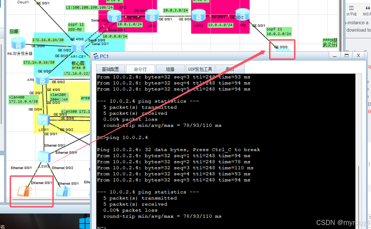
可以看到非常顺利
实验到这说明MPLS VPN就配置成功了!!!


 1489
1489

 被折叠的 条评论
为什么被折叠?
被折叠的 条评论
为什么被折叠?
 到【灌水乐园】发言


