


目录
系统采用Ubuntu 22,X86 64。
1. 安装ft260驱动
新版本的Linux内核是自带hid-ft260.ko的。
sudo modprobe hid-ft260然后执行lsmod查看:
$ lsmod
Module                  Size  Used by
hid_ft260              45056  0
usbhid                 77824  1 hid_ft260
hid                   180224  2 usbhid,hid_ft260
2. 编译ft260源码
下载ft260驱动源代码
git clone https://github.com/MichaelZaidman/hid-ft260.git进入hid-ft260,编译
make编辑一下makefile文件,增加install部分:
install:
	rmmod hid-ft260 || true
	insmod hid-ft260.ko || true
	mkdir -p /usr/lib/modules/$(shell uname -r)/kernel/drivers/hid/ || true
	cp -f ./hid-ft260.ko /usr/lib/modules/$(shell uname -r)/kernel/drivers/hid/ || true
	depmod -a
3. 通过sysfs配置ft260设备
可以在shell里面先执行(每次拔插后都要运行这个脚本),这个脚本在hid-ft260的源文件夹里面。
$ . ./setenv.sh
sysfs_i2c_11
sysfs_ttyFT0
返回2个设备,sysfs_i2c_xx表示i2c的接口,sysfs_ttyFTx表示uart的接口。这个接口类型由硬件跳线DCNF0和DCNF1决定,当前设置是0b11的配置。
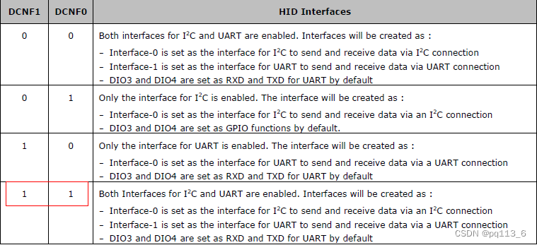
注意,不管哪种配置,返回的都是2个接口,因为0b00和0b11是一样的,0b01和0b10是只有一个接口,要么是串口,要么是i2c.
查看2个接口的信息:
$ echo $sysfs_i2c_11
/sys/bus/hid/drivers/ft260/0003:0403:6030.0007
$ echo $sysfs_ttyFT0
/sys/bus/hid/drivers/ft260/0003:0403:6030.0008/tty
查看接口的所有属性:
$ ls $sysfs_i2c_11
chip_mode  driver      gpioa_func  hid_over_i2c_en  i2c_reset  power_saving_en    subsystem       uart_mode
clock      gpio        gpiochip0   i2c-11           modalias   pwren_status       suspend_status  uevent
clock_ctl  gpio2_func  gpiog_func  i2c_enable       power      report_descriptor  uart_dcd_ri
以chip_mode为例,查看该属性
ls -l $sysfs_i2c_11/chip_mode
-r--r--r-- 1 root root 4096  4月 28 15:37 /sys/bus/hid/drivers/ft260/0003:0403:6030.0007/chip_mode
这个属性只读,然后输出内容:
$ cat $sysfs_i2c_11/chip_mode
3
对应DCNF0和DCNF1的设置0b11。
3.1 多功能GPIO配置
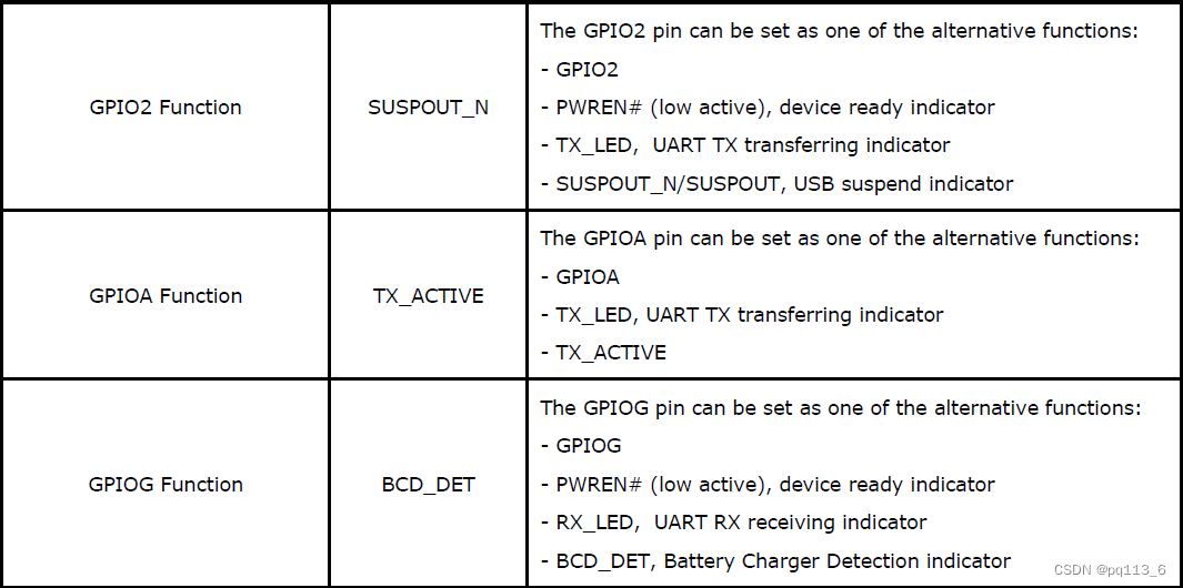
FT260的IO都是多功能,但是大部分是2个功能复用,当默认功能禁止时,自动变为GPIO,例如pin10可以是RXD和GPIOC,RXD是默认功能,当UART功能关闭时,这个管脚自动设置为GPIOC。FT260有3个特殊的多功能GPIO,他们是GPIO 2(pin 14), GPIOA (pin 7), and GPIOG (pin 27),它们可以通过eFuse、EEPROM或USB命令配置。
接口的所有属性中gpio2_func、gpioa_func、gpiog_func分别对应这3个GPIO的功能配置。默认功能是:
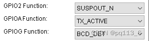
3个GPIO的功能如下:
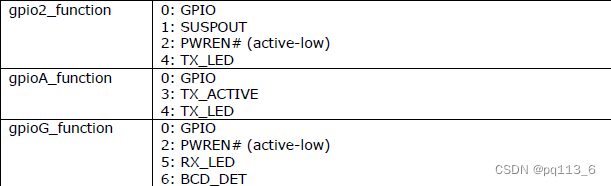
GPIO2的功能设定值含义如下:
0 - GPIO2,1 - SUSPOUT_N, 2 - PWREN, 4 - TX_LED
GPIOA的功能设定值含义如下:
0 - GPIOA,3 - TX_ACTIVE, 4 - TX_LED
GPIOG的功能设定值含义如下:
0 - GPIOG,2 - PWREN,5 - RX_LED, 6 - BCD_DET
读取对应gpio的func结果如下:
$ . ./setenv.sh
sysfs_i2c_11
sysfs_ttyFT0
$ cat $sysfs_i2c_11/gpio2_func
1
$ cat $sysfs_i2c_11/gpioa_func
3
$ cat $sysfs_i2c_11/gpiog_func
6
配置其他参数,例如将pin 14配置为GPIO2
sudo bash -c "echo 0 > $sysfs_i2c_11/gpio2_func"运行结果如下:
$ sudo bash -c "echo 0 > $sysfs_i2c_11/gpio2_func"
$ cat $sysfs_i2c_11/gpio2_func
0
其他的GPIO可以通过DCNF0、DCNF1 配置UART和I2C关闭来使能GPIO。
3.2 控制GPIO
正常使用sysfs操作gpio是通过echo命令将GPIO引脚导出到用户空间:
sudo bash -c "echo <GPIO_NUMBER> > $sysfs_i2c_11/gpio/export"注意,gpio编号不是2,a,g,但是这样无效。要先控制GPIO,需要先将对应的GPIO配置为GPIO模式,默认是没有gpio的。
可以先列一下/sys/class/gpio/
$ ls /sys/class/gpio
export  gpiochip512  unexport
gpiochip512, 偏移值是512,GPIO2的编号是514,GPIOA的编号为512+6=518, GPIOG的编号为512+12=525
sudo bash -c 'echo 514 > /sys/class/gpio/export'
sudo bash -c 'echo 518 > /sys/class/gpio/export'
sudo bash -c 'echo 524 > /sys/class/gpio/export'
设置为输出
sudo bash -c 'echo out > /sys/class/gpio/gpio514/direction'
sudo bash -c 'echo out > /sys/class/gpio/gpio518/direction'
sudo bash -c 'echo out > /sys/class/gpio/gpio524/direction'
输出高电平:
sudo bash -c 'echo 1 > /sys/class/gpio/gpio514/value'
sudo bash -c 'echo 1 > /sys/class/gpio/gpio518/value'
sudo bash -c 'echo 1 > /sys/class/gpio/gpio524/value'
3.3 配置i2c总线频率
sudo bash -c 'echo <clk> > $sysfs_i2c_11/clock'其中<clk>表示设置的频率,单位kHz,例如设置为400KHz
sudo bash -c 'echo 400 > $sysfs_i2c_11/clock'不过这样写无效,没有提示错误。但是量频率一直是100KHz。从github的issue里面也有人问这个问题,需要在sysfs下找出USB总线上的ft260设备。
$ ls /sys/bus/usb/devices
1-0:1.0  1-1:1.0  2-1    2-1:1.0    2-1.3      2-1.3:1.1  3-4      3-4:1.1  usb1  usb3
1-1      2-0:1.0  2-1.1  2-1.1:1.0  2-1.3:1.0  3-0:1.0    3-4:1.0  4-0:1.0  usb2  usb4
然后通过lsusb看一下ft260在哪个bus上
Bus 003 Device 026: ID 0403:6030 Future Technology Devices International, Ltd FT260结合lsusb和ls /sys/bus/usb/devices的结果,bus3上有2个设备,3-0和3-4,一般3-0是hub本身,所以3-4应该是FT260
$ cat /sys/bus/usb/devices/3-4/idProduct
6030
$ cat /sys/bus/usb/devices/3-4/idVendor
0403
找到对应文件clock
$ cat /sys/bus/usb/devices/3-4:1.0/0003:0403:6030.0023/clock
100
操作这个文件即可
$ sudo bash -c 'echo 400 > /sys/bus/usb/devices/3-4:1.0/0003:0403:6030.0023/clock'
$ cat /sys/bus/usb/devices/3-4:1.0/0003:0403:6030.0023/clock
400
4. UART
对于UART功能,操作比较简单,和普通的串口使用一样,只是设备名变为ttyFT0了。例如使用cutecom就可以使用。
5. 使用i2c-tools交互I2C设备
5.1 安装i2c-tools
sudo apt-get install i2c-tools5.2 探测I2C设备
如之前的信息,本例中i2c设备是i2c_11,所以通过i2cdetect探测设备
$ sudo i2cdetect -y 11
Warning: Can't use SMBus Quick Write command, will skip some addresses
     0  1  2  3  4  5  6  7  8  9  a  b  c  d  e  f
00:
10:
20:
30: -- -- -- -- -- -- -- --
40:
50: 50 -- -- -- -- -- -- -- -- -- -- -- -- -- -- --
60:
70: 这里的-y选项用于关闭交互模式,这样在运行时不会显示警告信息。数字11代表I2C总线的编号,根据你的系统配置,这个编号可能会有所不同。
输出结果是遍历所有的I2C地址,因为总线上只有一个AT24C02的设备,所以可以看到输出结果只有0x50这个设备。
5.3 读取所有寄存器数据
假设I2C总线上接的设备是AT24C02(UMFT260EV1A板子上默认自带),EEPROM,设备地址为0x50。
$ sudo i2cdump -y 11 0x50
No size specified (using byte-data access)
     0  1  2  3  4  5  6  7  8  9  a  b  c  d  e  f    0123456789abcdef
00: 45 31 03 04 30 60 00 00 a0 32 46 54 44 49 2c 0a    E1??0`..?2FTDI,?
10: 36 0c 00 00 60 20 cf be 00 00 00 00 00 00 00 00    6?..` ??........
20: 40 00 00 00 00 00 00 00 00 00 00 00 0a 03 46 00    @...........??F.
30: 54 00 44 00 49 00 0c 03 46 00 54 00 32 00 36 00    T.D.I.??F.T.2.6.
40: 30 00 00 00 00 00 00 00 00 00 00 00 00 00 00 00    0...............
50: 00 00 00 00 00 00 00 00 00 00 00 00 00 00 00 00    ................
60: 00 00 00 00 00 00 00 00 00 00 00 00 00 00 00 00    ................
70: 00 00 00 00 00 00 00 00 00 00 00 00 00 00 00 00    ................
80: 00 00 00 00 00 00 00 00 00 00 00 00 00 00 00 00    ................
90: 00 00 00 00 00 00 00 00 00 00 00 00 00 00 00 00    ................
a0: 00 00 00 00 00 00 00 00 00 00 00 00 00 00 00 00    ................
b0: 00 00 00 00 00 00 00 00 00 00 00 00 00 00 00 00    ................
c0: 00 00 00 00 00 00 00 00 00 00 00 00 00 00 00 00    ................
d0: 00 00 00 00 00 00 00 00 00 00 00 00 00 00 00 00    ................
e0: 00 00 00 00 00 00 00 00 00 00 00 00 00 00 00 00    ................
f0: 00 00 00 00 00 00 00 00 00 00 00 00 00 00 b8 14    ..............??
5.4 读取和写入
- 读取寄存器:
sudo i2cget -y <bus> <device-address> <register-address> [w]
将<device-address>替换为你要操作的设备的地址,<register-address>替换为你要读取或写入的寄存器的地址,<value>替换为你要写入的值(如果是写入操作的话)。[w]表示值的位宽,可以是b(字节)、w(字)或l(长整数),根据寄存器的大小来选择。
$ sudo i2cget -y 11 0x50 0x10 b
0x36- 写入寄存器:
sudo i2cset -y <bus> <device-address> <register-address> <value> [w]参数含义等同读取。
$ sudo i2cset -y 11 0x50 0x80 0x55 b
$ sudo i2cget -y 11 0x50 0x80 b
0x55
$ sudo i2cset -y 11 0x50 0x80 0x00 b
$ sudo i2cget -y 11 0x50 0x80 b
0x00
5.5 16位地址的读写
前面的命令中,地址都是8位地址,如果是16位地址,需要通过i2ctransfer实现。
i2ctransfer [-f] [-y] [-v] [-V] [-a] I2CBUS DESC [DATA] [DESC [DATA]]...-f: 强制模式,如果目标 I2C 设备未响应,则不等待超时并立即返回。
-y: 对于读取操作,如果读取的数据少于请求的字节数,则不会报错。
-v: 详细模式,显示更多输出信息。
-V:版本信息,显示 i2ctransfer 的版本。
-a:在每次 I/O 操作后,显示 I2C 总线的地址和值。
I2CBUS: 指定要使用的 I2C 总线。通常是一个数字,例如 0、1 等,可以使用 ls /dev/i2c-* 来查看可用的 I2C 总线。
DES: 描述符,用于指定 I2C 消息的属性。例如写的格式:w[len]@[addr],读的格式:r[len]@[addr]。
DATA:可选,数据,一般写的时候需要写。
比如从16位地址0x0000读入4字节的命令:
sudo i2ctransfer -y 11 w2@0x50 0x00 0x00 r4从16位地址0x0000写4字节0x11 0x22 0x33 0x44的命令:
sudo i2ctransfer -y 11 w6@0x50 0x00 0x00 0x11 0x22 0x33 0x44如果是8位地址,只要把后面接的写地址部分改为1个字节就可以。
sudo i2ctransfer -y 11 w1@0x50 0x00 r4
sudo i2ctransfer -y 11 w5@0x50 0x00 0x11 0x22 0x33 0x44
6. 通过libi2c交互I2C设备(C语言)
6.1 安装libi2c
sudo apt-get install i2c-tools libi2c-dev6.2 加载i2c内核模块
sudo modprobe i2c-core
sudo modprobe i2c-dev
sudo modprobe i2c-smbus
不知道为什么,lsmod只能看到i2c-smbus。
6.3 C语言使用范例
6.3.1 头文件
#include <stdio.h>
#include <stdlib.h>
#include <fcntl.h>
#include <unistd.h>
#include <sys/ioctl.h>
#include <linux/i2c-dev.h>
6.3.2 找到FT260的总线编号
定义宏定义:
#define DEVICE_DIR "/sys/bus/i2c/devices/"
#define BUFFER_SIZE 256
#define TARGET_NAME "FT260 usb-i2c bridge\n"
创建函数findFT260, 返回总线编号,这个函数只能找到第一个FT260设备,如果是多个FT260设备,需要增加辨别判断,可以通过libusb获取serial number识别。
int findFT260(void)
{
    DIR *dir;
    struct dirent *entry;
    char device_path[PATH_MAX];
    char name_path[PATH_MAX];
    char buffer[BUFFER_SIZE];
    ssize_t bytesRead;
    int fd;

    // 打开目录
    dir = opendir(DEVICE_DIR);
    if (dir == NULL)
    {
        perror("opendir");
        return -1;
    }

    // 遍历目录条目
    while ((entry = readdir(dir)) != NULL)
    {

    }
}
while循环中逐个读入name判断。
        // 构建设备名称文件的路径
        snprintf(name_path, sizeof(name_path), "%s%s/name", DEVICE_DIR, entry->d_name);
        // 打开设备名称文件
        fd = open(name_path, O_RDONLY);
        if (fd == -1) {
            perror("open");
            continue;
        }

        // 读取设备名称
        bytesRead = read(fd, buffer, BUFFER_SIZE - 1);
        close(fd);
        if (bytesRead > 0) {
            buffer[bytesRead] = '\0'; // 确保字符串以null结尾
            printf("Device name: %s\n", buffer);
        } else {
            perror("read");
            // 关闭文件
            return -2;
        }

        if (strcmp(buffer, TARGET_NAME) == 0)
        {
            int number = 0;
            int is_number = 0; // 标志位,表示是否开始读取数字

            // 遍历字符串
            for (size_t i = 0; entry->d_name[i] != '\0'; ++i)
            {
                if (isdigit(entry->d_name[i]))
                { // 如果字符是数字
                    if (!is_number)
                    { // 如果之前还没读取过数字,开始读取
                        is_number = 1;
                        number = 0; // 重置number为0,准备读取新的数字
                    }
                    number = number * 10 + (entry->d_name[i] - '0'); // 将数字添加到number中
                }
                else
                {
                    is_number = 0; // 如果不是数字,则停止读取数字
                }
            }
            return number;
        }
6.3.3 打开设备
int file;
if ((file = open(i2c_path, O_RDWR)) < 0)
{
    perror("Failed to open the i2c bus\n");
    exit(1);
}
6.3.4 设置I2C设备地址
通过ioctl设置。
if (ioctl(file, I2C_SLAVE, addr) < 0)
{
    perror("Failed to acquire bus access and/or talk to slave");
    close(file);
    exit(1);
}
6.3.5 从设备读数据
int i2cRead(int fd, unsigned char slave_addr, unsigned char reg_addr_width,
    unsigned int reg_addr, unsigned char *pdat, unsigned int len)
fd - 设备句柄
slave_addr - 从机地址,7位地址
reg_addr_width - 从机内部寄存器地址宽度,有效值为0,8,16
reg_addr - 从机内部寄存器地址,reg_addr_width为0时这个参数无效
pdat - 读入数据的缓存
len - 读入字节数
读写都是可以通过ioctl,对于读来说,需要先写寄存器地址,在读入数据。
unsigned char outbuf[2];
int offset = 0;
struct i2c_rdwr_ioctl_data packets;
struct i2c_msg messages[2];
根据寄存器地址宽度配置写寄存器地址的数据
if(reg_addr_width == 16)
{
    outbuf[offset++] = (unsigned char)(reg_addr >> 8);
    outbuf[offset++] = (unsigned char)reg_addr;
}
else if (reg_addr_width == 8)
    outbuf[offset++] = (unsigned char)reg_addr;
如果有寄存器地址需要发送,需要发送2个信息给驱动,注意2个信息的flag的区别,0表示写。
if (reg_addr_width > 0)
{
    messages[0].addr = slave_addr;
    messages[0].flags = 0;
    messages[0].len = offset;
    messages[0].buf = outbuf;

    /* The data will get returned in this structure */
    messages[1].addr = slave_addr;
    messages[1].flags = I2C_M_RD/* | I2C_M_NOSTART*/;
    messages[1].len = len;
    messages[1].buf = pdat;

    /* Send the request to the kernel and get the result back */
    packets.msgs = messages;
    packets.nmsgs = 2;
}
如果没有寄存器地址,则直接读数据即可。
else
{
    messages[0].addr = slave_addr;
    messages[0].flags = I2C_M_RD/* | I2C_M_NOSTART*/;
    messages[0].len = len;
    messages[0].buf = pdat;

    /* Send the request to the kernel and get the result back */
    packets.msgs = messages;
    packets.nmsgs = 1;
}
最后发送出去
if(ioctl(fd, I2C_RDWR, &packets) < 0)
{
    perror("i2cRead ioctl fail");
    return -1;
}
return 0;
6.3.6 写数据到从设备
写数据必须一笔信息发送出去,其他类似读操作。
int i2cWrite(int fd, unsigned char slave_addr, unsigned char reg_addr_width,
    unsigned int reg_addr, unsigned char *pdat, unsigned int len)
{
    struct i2c_rdwr_ioctl_data packets;
    struct i2c_msg messages[1];
    unsigned char *outbuf = NULL;
    int offset = 0;
    unsigned int total = len;
    if(reg_addr_width == 16)
        total = len + 2;
    else if(reg_addr_width == 8)
        total = len + 1;
    else
        total = len;
    outbuf = malloc(total);
    if (!outbuf)
    {
        perror("Error: No memory for buffer");
        return -1;
    }

    if(reg_addr_width == 16)
    {
        outbuf[offset++] = (unsigned char)(reg_addr >> 8);
        outbuf[offset++] = (unsigned char)reg_addr;
    }
    else if(reg_addr_width == 8)
        outbuf[offset++] = (unsigned char)reg_addr;

    memcpy(outbuf + offset, pdat, len);

    messages[0].addr = slave_addr;
    messages[0].flags = 0;
    messages[0].len = total;
    messages[0].buf = outbuf;

    packets.nmsgs = 1;
    packets.msgs = messages;

    if(ioctl(fd, I2C_RDWR, &packets) < 0)
    {
        perror("i2cWrite ioctl fail");
        return -1;
    }
    return 0;
}
6.3.6 设置频率
参考3.3的方式设置,首先是要找到设备的文件夹位置。
先建一个函数用于根据VID、PID找到设备的文件夹位置。在文件夹下读取idVendor和idProduct文件,判断VID和PID即可。
int check_usb_device(const char *path, const char *vid, const char *pid)
{
    char vid_path[1024];
    char pid_path[1024];
    char vid_buf[16];
    char pid_buf[16];
    ssize_t bytes_read;

    snprintf(vid_path, sizeof(vid_path), "%s/idVendor", path);
    snprintf(pid_path, sizeof(pid_path), "%s/idProduct", path);

    int vid_fd = open(vid_path, O_RDONLY);
    int pid_fd = open(pid_path, O_RDONLY);

    if (vid_fd == -1 || pid_fd == -1) {
        perror("open");
        if (vid_fd != -1) close(vid_fd);
        if (pid_fd != -1) close(pid_fd);
        return -1;
    }

    bytes_read = read(vid_fd, vid_buf, sizeof(vid_buf) - 1);
    if (bytes_read <= 0) {
        perror("read");
        close(vid_fd);
        close(pid_fd);
        return -1;
    }
    if(bytes_read > 4)
        bytes_read = 4;
    vid_buf[bytes_read] = '\0'; // Ensure string is null-terminated

    bytes_read = read(pid_fd, pid_buf, sizeof(pid_buf) - 1);
    if (bytes_read <= 0) {
        perror("read");
        close(vid_fd);
        close(pid_fd);
        return -1;
    }
    if(bytes_read > 4)
        bytes_read = 4;
    pid_buf[bytes_read] = '\0'; // Ensure string is null-terminated

    close(vid_fd);
    close(pid_fd);

    // Compare VID and PID
    if (strcmp(vid, vid_buf) == 0 && strcmp(pid, pid_buf) == 0) {
        return 1; // Found a match
    }

    return 0; // No match
}
找个这个文件夹后继续打开这个文件夹下名字带1.0的文件夹。
int findClockPath(char *path, int len)
{
    DIR *dir;
    struct dirent *entry;
    char full_path[1024];
    snprintf(full_path, sizeof(full_path), "%s:1.0/", path);
    dir = opendir(full_path);
    if (dir == NULL)
    {
        perror("opendir");
        return -1;
    }
    while ((entry = readdir(dir)) != NULL)
    {
        // 忽略.和..目录项
        if (strcmp(entry->d_name, ".") == 0 || strcmp(entry->d_name, "..") == 0)
        {
            continue;
        }

        // 构建完整路径
        char *last_slash = strrchr(path, '/');
        snprintf(full_path, sizeof(full_path), "%s/%s:1.0/%s", path, last_slash, entry->d_name);
        printf("full path:%s\n", full_path);
        // 检查是否是目录,并且名称包含指定的vendor_product_id
        struct stat st;
        if (stat(full_path, &st) == 0 && S_ISDIR(st.st_mode))
        {
            // 检查目录名是否包含指定的vendor_product_id
            if (strstr(entry->d_name, "0403:6030") != NULL)
            {
                printf("Found directory: %s\n", full_path);
                snprintf(path, len, "%s", full_path);
                closedir(dir);
                return 0;
            }
        }
    }
    return -1;
}
设置频率的函数,将设置的频率写入clock文件即可。
int i2cSetFreq(int freq)
{
    DIR *dir;
    struct dirent *entry;
    char path[1024];

    dir = opendir("/sys/bus/usb/devices/");
    if (dir == NULL) {
        perror("opendir");
        return 1;
    }

    while ((entry = readdir(dir)) != NULL) {
        if (entry->d_type == DT_DIR && entry->d_name[0] != '.') {
            snprintf(path, sizeof(path), "/sys/bus/usb/devices/%s", entry->d_name);
            if (check_usb_device(path, VID, PID) == 1) {
                printf("Found FT260 device at: %s\n", path);

                closedir(dir);
                if(findClockPath(path, sizeof(path)) == 0)
                {
                    int fd;
                    char buffer[6];
                    char clockFilePath[2048];
                    snprintf(buffer, sizeof(buffer), "%d\n", freq);
                    snprintf(clockFilePath, sizeof(clockFilePath), "%s/clock", path);
                    // 尝试以写入模式打开文件
                    printf("clock:%s\n", clockFilePath);
                    fd = open(clockFilePath, O_WRONLY);
                    if (fd == -1)
                    {
                        // 如果打开失败,打印错误并退出
                        perror("open");
                        return -2;
                    }
                    // 写入数据到文件
                    ssize_t bytes_written = write(fd, buffer, strlen(buffer));
                    if (bytes_written == -1) {
                        // 如果写入失败,打印错误并关闭文件
                        perror("write");
                        close(fd);
                        return -3;
                    }
                    // 关闭文件
                    if (close(fd) == -1) {
                        // 如果关闭失败,打印错误但忽略,因为数据已经写入
                        perror("close");
                        return -4;
                    }
                    return 0;
                }
            }
        }
    }

    closedir(dir);
    return 0;
}
进入这个文件夹,应该以:0403:6030为关键字找到这个特殊的文件夹
7 通过libgpiod控制GPIO(C语言)
7.1 安装libgpiod
sudo apt-get install libgpiod-dev7.2 找到GPIO
$ ls /sys/class/gpio/
export  gpiochip512  unexport
$ ls /sys/class/gpio/gpiochip512
base  device  label  ngpio  power  subsystem  uevent
$ cat /sys/class/gpio/gpiochip512/label
ft260_0003:0403:6030.000F
$ cat /sys/class/gpio/gpiochip512/base
512
$ cat /sys/class/gpio/gpiochip512/ngpio
14
只要找到base的值。
int findGpio(int *base)
{
    DIR *dir;
    struct dirent *entry;
    char full_path[1024];
    dir = opendir("/sys/class/gpio/");
    if (dir == NULL)
    {
        perror("opendir");
        return -1;
    }
    while ((entry = readdir(dir)) != NULL)
    {
        // 忽略.和..目录项
        if (strcmp(entry->d_name, ".") == 0 || strcmp(entry->d_name, "..") == 0)
        {
            continue;
        }
        printf("folder:%s\n", entry->d_name);
        if (strstr(entry->d_name, "gpiochip") != NULL)
        {
            snprintf(full_path, sizeof(full_path), "/sys/class/gpio/%s/label", entry->d_name);
            printf("full path:%s\n", full_path);
            int fd;
            fd = open(full_path, O_RDONLY);
            if (fd == -1)
            {
                // 如果打开失败,打印错误
                perror("open label");
                continue;
            }
            char buffer[256];
            ssize_t bytes_read = read(fd, buffer, sizeof(buffer) - 1);
            if (bytes_read == -1)
            {
                // 如果写入失败,打印错误并关闭文件
                perror("");
                close(fd);
                continue;
            }
            // 关闭文件
            if (close(fd) == -1)
            {
                // 如果关闭失败,打印错误但忽略,因为数据已经写入
                perror("close");
                continue;
            }
            printf("    label:%s\n", buffer);
            if (strstr(buffer, "ft260") != NULL)
            {
                snprintf(full_path, sizeof(full_path), "/sys/class/gpio/%s/base", entry->d_name);
                fd = open(full_path, O_RDONLY);
                if (fd == -1)
                {
                    // 如果打开失败,打印错误
                    perror("open");
                    continue;
                }
                ssize_t bytes_read = read(fd, buffer, strlen(buffer));
                if (bytes_read == -1)
                {
                    // 如果写入失败,打印错误并关闭文件
                    perror("");
                    close(fd);
                    continue;
                }
                buffer[bytes_read] = '\0';
                // 关闭文件
                if (close(fd) == -1)
                {
                    // 如果关闭失败,打印错误但忽略,因为数据已经写入
                    perror("close");
                    continue;
                }
                char *endptr;
                *base = strtol(buffer, &endptr, 10);
                printf("gpio base=%d\n", *base);
                return 0;
            }
        }
    }
    return -1;
}
7.3 打开和关闭GPIO CHIP
路径在/dev/中,类似“/dev/gpiochip0”
struct gpiod_chip *gpiochipFT;
gpiochipFT = gpiod_chip_open("/dev/gpiochip0");
if (!gpiochipFT)
{
    perror("gpio open fail");
    return;
}
关闭:
gpiod_chip_close(gpiochipFT);7.4 获取GPIO句柄和释放
获取某个GPIO的句柄
struct gpiod_line *gpio2;
gpio2= gpiod_chip_get_line(gpiochipFT, 2);
if (!gpio2)
{
    gpiod_chip_close(gpiochipFT);
    perror("gpio2 get line fail");
    return;
}
注意对应的GPIO要先设置为GPIO模式,否则会返回错误。
用完要释放:
gpiod_line_release(gpio2, &req); 7.5 设置输出或输入
设置为输出:
req = gpiod_line_request_output(gpio2, "blink", 0);
if (req)
{
    gpiod_chip_close(gpiochipFT);
    fprintf(stderr, "GPIO2 request error.\n");
    return;
}
字符串“blink”表示该GPIO的用户名,0表示默认电平为低电平。
可以通过gpiod_line_request_input设置为输入
req = gpiod_line_request_input(gpio2, "blink");7.6 输出高低
while (1)
{
    /* 设置引脚电平 */
    gpiod_line_set_value(gpio2, 1);
    printf("set GPIO2 to 0\n");
    usleep(500 * 1000);
    gpiod_line_set_value(gpio2, 0);
    printf("set GPIO2 to 1\n");
    usleep(500 * 1000);
}
7.6 读入
while (1)
{
    int value;
    /* 设置引脚电平 */
    gpiod_line_set_value(gpio2, 1);
    value = gpiod_line_get_value(gpio2);
    printf("set GPIO2 to %d\n", value);
    usleep(500 * 1000);
    gpiod_line_set_value(gpio2, 0);
    value = gpiod_line_get_value(gpio2);
    printf("set GPIO2 to %d\n", value);
    usleep(500 * 1000);
}


 418
418

 被折叠的 条评论
为什么被折叠?
被折叠的 条评论
为什么被折叠?
 到【灌水乐园】发言


