


首先我们来讲最简单的GPIO配置
代码生成
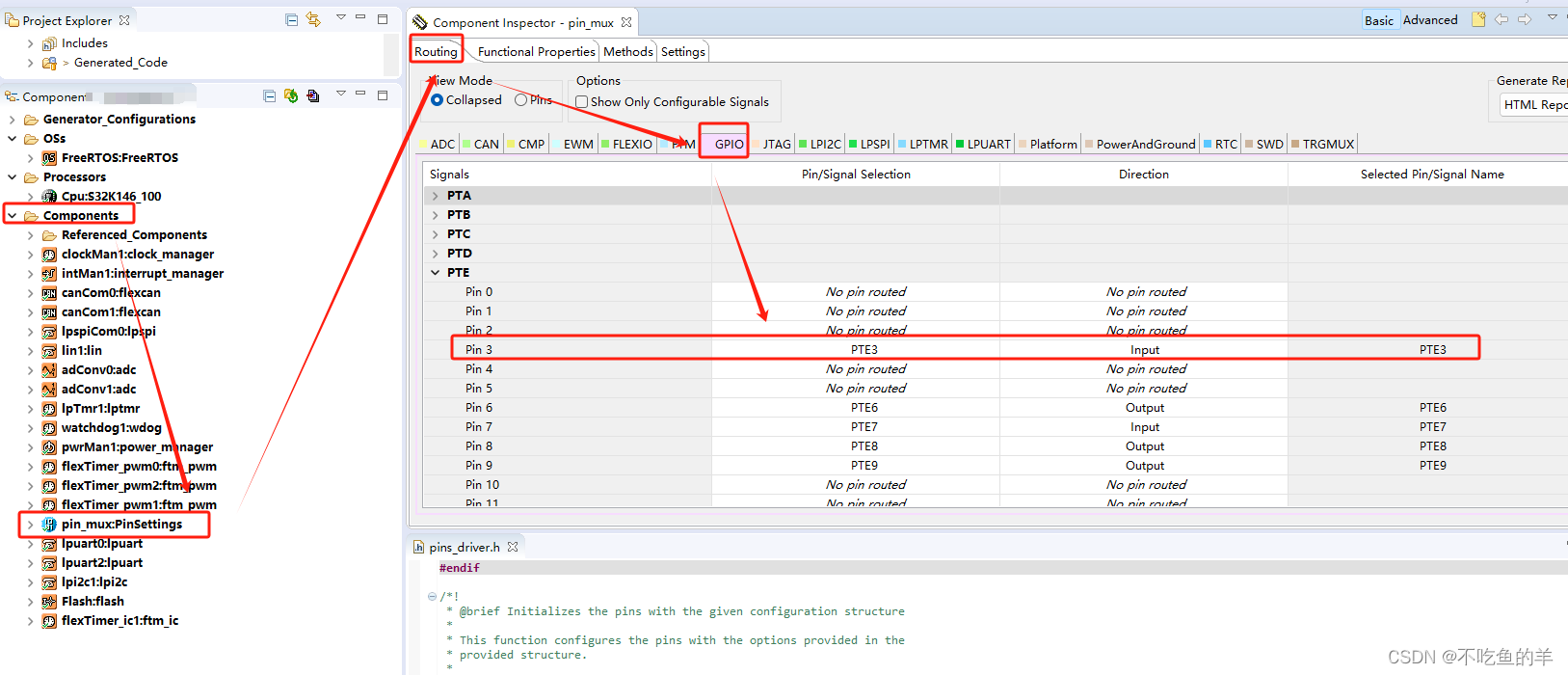
按照下图步骤就能配置一个基本的GPIO口,在组件里面选择pin_mux,选中就能配置使能和方向,no pin routed就是没有配置的。GPIO口分ABCDE组,每组从0到最大的序号。
 然后在functional properties里面配置具体每一个引脚的复用、锁定、上拉下拉、数字过滤、输出初始值等等……

于是我们生成代码来看看,在文件pin_mux.c当中,会生成一个类型为pin_settings_config_t的g_pin_mux_InitConfigArr结构体数组。数组长度NUM_OF_CONFIGURED_PINS是GPIO口总数量,在pin_mux.h当中,也是会随着代码一起生成。
pin_settings_config_t g_pin_mux_InitConfigArr[NUM_OF_CONFIGURED_PINS] =
{
    ……
    {
        .base          = PORTB,
        .pinPortIdx    = 16u,
        .pullConfig    = PORT_INTERNAL_PULL_NOT_ENABLED,
        .passiveFilter = false,
        .driveSelect   = PORT_LOW_DRIVE_STRENGTH,
        .mux           = PORT_MUX_AS_GPIO,
        .pinLock       = false,
        .intConfig     = PORT_DMA_INT_DISABLED,
        .clearIntFlag  = false,
        .gpioBase      = PTB,
        .direction     = GPIO_OUTPUT_DIRECTION,
        .digitalFilter = false,
        .initValue     = 0u,
    },
    {
        .base          = PORTB,
        .pinPortIdx    = 15u,
        .pullConfig    = PORT_INTERNAL_PULL_NOT_ENABLED,
        .passiveFilter = false,
        .driveSelect   = PORT_LOW_DRIVE_STRENGTH,
        .mux           = PORT_MUX_ADC_INTERLEAVE,
        .pinLock       = false,
        .intConfig     = PORT_DMA_INT_DISABLED,
        .clearIntFlag  = false,
        .gpioBase      = PTB,
        .digitalFilter = false,
    }
    ……
}
配置对应
接下来我们一项一项看每一项配置是怎么对应代码的,base对应的是所在组的地址,gpioBase对应的是所在组的控制寄存器的地址。
PE自己对应的,使能就有,不用配置。
/** Peripheral PORTB base address */
#define PORTB_BASE                               (0x4004A000u)
/** Peripheral PORTB base pointer */
#define PORTB                                    ((PORT_Type *)PORTB_BASE)

/** Peripheral PTB base address */
#define PTB_BASE                                 (0x400FF040u)
/** Peripheral PTB base pointer */
#define PTB                                      ((GPIO_Type *)PTB_BASE)
pinPortIdx是该GPIO口在组内的序号
pullConfig有三个可选,上拉下拉和悬浮。
/*!
 * @brief Internal resistor pull feature selection
 * Implements : port_pull_config_t_Class
 */
typedef enum
{
    PORT_INTERNAL_PULL_NOT_ENABLED   = 0U,  /*!< internal pull-down or pull-up resistor is not enabled.           */
    PORT_INTERNAL_PULL_DOWN_ENABLED  = 1U,  /*!< internal pull-down resistor is enabled. @internal gui name="Down"*/
    PORT_INTERNAL_PULL_UP_ENABLED    = 2U   /*!< internal pull-up resistor is enabled. @internal gui name="Up"    */
} port_pull_config_t;
对应配置的pull select,不过要先将pull enable使能才行,不然就是默认的PORT_INTERNAL_PULL_NOT_ENABLED

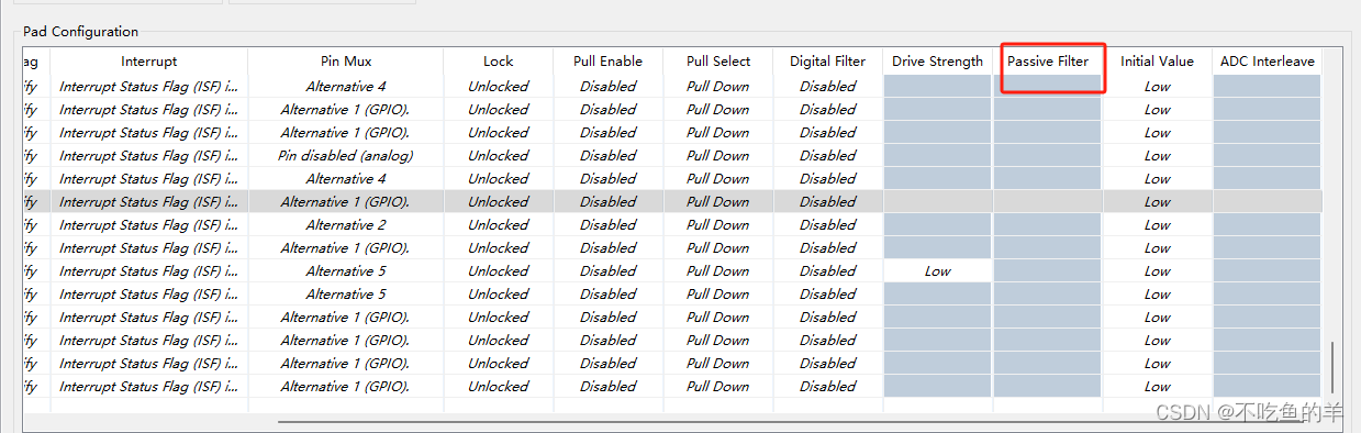
passiveFilter被动滤波,一般不用,对应配置当中的Passive Filter。被动滤波是相对于主动滤波来看的,这种没有电源,纯纯靠电阻电容电感组成的滤波电路就是被动滤波,我们GPIO口这种纯上下拉就属于被动滤波。主动滤波是有电源的,滤波电路里面有放大器、控制器之类的。
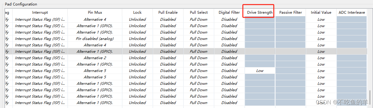
driveSelect驱动选择,就是上下拉的力量大小,电阻越小拉的电流越大。
/*!
 * @brief Configures the drive strength.
 * Implements : port_drive_strength_t_Class
 */
typedef enum
{
#if FEATURE_PINS_HAS_DRIVE_STRENGTH_CONTROL
    PORT_STRENGTH_DISABLED      = 0U, /*!< Output driver disabled                                         */
    PORT_LOW_DRIVE_STRENGTH     = 1U, /*!< Low drive strength is configured. Resistor is set to 240 Ohm   */
    PORT_STR1_DRIVE_STRENGTH    = 1U, /*!< Resistor is set to 240 Ohm                                     */
    PORT_STR2_DRIVE_STRENGTH    = 2U, /*!< Resistor is set to 240 / 2 Ohm = 120 Ohm                       */
    PORT_STR3_DRIVE_STRENGTH    = 3U, /*!< Resistor is set to 240 / 3 Ohm = 80 Ohm                        */
    PORT_STR4_DRIVE_STRENGTH    = 4U, /*!< Resistor is set to 240 / 4 Ohm = 60 Ohm                        */
    PORT_STR5_DRIVE_STRENGTH    = 5U, /*!< Resistor is set to 240 / 5 Ohm = 48 Ohm                        */
    PORT_STR6_DRIVE_STRENGTH    = 6U, /*!< Resistor is set to 240 / 6 Ohm = 40 Ohm                        */
    PORT_STR7_DRIVE_STRENGTH    = 7U, /*!< Resistor is set to 240 / 7 Ohm = 34 Ohm                        */
    PORT_HIGH_DRIVE_STRENGTH    = 7U  /*!< High drive strength is configured. Resistor is set to 240 Ohm  */
#else /* if not FEATURE_PINS_HAS_DRIVE_STRENGTH_CONTROL */
    PORT_LOW_DRIVE_STRENGTH     = 0U,    /*!< low drive strength is configured. @internal gui name="Low"  */
    PORT_HIGH_DRIVE_STRENGTH    = 1U     /*!< high drive strength is configured. @internal gui name="High"*/
#endif /* if FEATURE_PINS_HAS_DRIVE_STRENGTH_CONTROL */
} port_drive_strength_t;
对应配置Drive Strength驱动强度,例子当中的这个芯片没那么多可以选的,只能选个low或者high。
mux复用功能,一般都是PORT_MUX_AS_GPIO,ALT也就是alternative,如果复用ADC就是用PORT_MUX_ADC_INTERLEAVE。
/*!
 * @brief Configures the Pin mux selection
 * Implements : port_mux_t_Class
 */
typedef enum
{
    PORT_PIN_DISABLED            = 0U,  /*!< corresponding pin is disabled, but is used as an analog pin       */
    PORT_MUX_AS_GPIO             = 1U,  /*!< corresponding pin is configured as GPIO                           */
    PORT_MUX_ALT2                = 2U,  /*!< chip-specific                                                     */
    PORT_MUX_ALT3                = 3U,  /*!< chip-specific                                                     */
    PORT_MUX_ALT4                = 4U,  /*!< chip-specific                                                     */
    PORT_MUX_ALT5                = 5U,  /*!< chip-specific                                                     */
    PORT_MUX_ALT6                = 6U,  /*!< chip-specific                                                     */
    PORT_MUX_ALT7                = 7U,  /*!< chip-specific                                                     */
#if FEATURE_PINS_HAS_ADC_INTERLEAVE_EN
    PORT_MUX_ADC_INTERLEAVE      = 8U   /*!< when selected, ADC Interleaved channel is connected to current pin
                                         *   and disconnected to opposed pin
                                         * ADC1_SE14-PTB15 | ADC1_SE15-PTB16 | ADC0_SE8-PTC0  | ADC0_SE9-PTC1
                                         * ADC1_SE14-PTB0  | ADC1_SE15-PTB1  | ADC0_SE8-PTB13 | ADC0_SE9-PTB14 */
#endif /* FEATURE_PINS_HAS_ADC_INTERLEAVE_EN */
} port_mux_t;
对应配置的pin mux,普通IO口就是GPIO,模拟口就是analog。

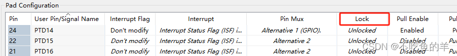
pinLock引脚锁对应lock,一般默认unlocked就行。
intConfig中断配置,要到对应的模块配置才行,不在GPIO口里面配置。
/*!
 * @brief Configures the interrupt generation condition.
 * Implements : port_interrupt_config_t_Class
 */
typedef enum
{
    PORT_DMA_INT_DISABLED  = 0x0U,  /*!< Interrupt/DMA request is disabled.                   */
    PORT_DMA_RISING_EDGE   = 0x1U,  /*!< DMA request on rising edge.                          */
    PORT_DMA_FALLING_EDGE  = 0x2U,  /*!< DMA request on falling edge.                         */
    PORT_DMA_EITHER_EDGE   = 0x3U,  /*!< DMA request on either edge.                          */
#if FEATURE_PORT_HAS_FLAG_SET_ONLY
    PORT_FLAG_RISING_EDGE  = 0x5U,  /*!< Flag sets on rising edge, no interrupt is generated. */
    PORT_FLAG_FALLING_EDGE = 0x6U,  /*!< Flag sets on falling edge, no interrupt is generated.*/
    PORT_FLAG_EITHER_EDGE  = 0x7U,  /*!< Flag sets on either edge, no interrupt is generated. */
#endif /* FEATURE_PORT_HAS_FLAG_SET_ONLY */
    PORT_INT_LOGIC_ZERO    = 0x8U,  /*!< Interrupt when logic 0.                              */
    PORT_INT_RISING_EDGE   = 0x9U,  /*!< Interrupt on rising edge.                            */
    PORT_INT_FALLING_EDGE  = 0xAU,  /*!< Interrupt on falling edge.                           */
    PORT_INT_EITHER_EDGE   = 0xBU,  /*!< Interrupt on either edge.                            */
    PORT_INT_LOGIC_ONE     = 0xCU,  /*!< Interrupt when logic 1.                              */
#if FEATURE_PORT_HAS_TRIGGER_OUT
    PORT_HIGH_TRIGGER_OUT  = 0xDU,  /*!< Enable active high trigger output, flag is disabled. */
    PORT_LOW_TRIGGER_OUT   = 0xEU   /*!< Enable active low trigger output, flag is disabled.  */
#endif /* FEATURE_PORT_HAS_TRIGGER_OUT */
} port_interrupt_config_t;
clearIntFlag和digitalFilter一般也是默认就行,对应interrupt flag和digital filter。
clearIntFlag是清除中断标志位的时候置起的标志位,极少使用。
digitalFilter数字滤波是复用为ADC采集的时候用的,使用硬件方式过滤噪声。

initValue是输出初始值,输入的IO口没有,只有输出引脚有,对应initial value。

接口函数
methods选项卡里面的接口函数跟展开pin_mux是一样的。生成的代码声明在pins_driver.h文件,函数原型在pins_driver.c文件,我们调用里面的接口就行。
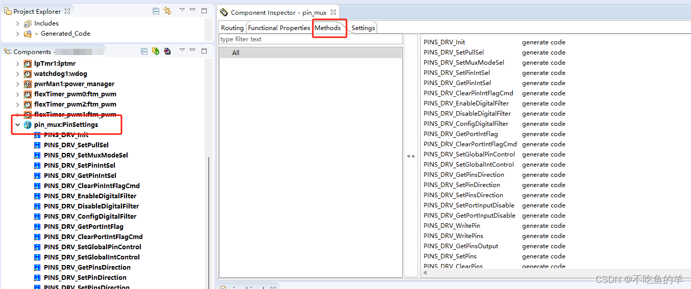
PINS_DRV_Init
这个是使用GPIO必须要调用的初始化接口,第一个入参是要初始化的GPIO数量,第二个入参是pin_settings_config_t类型的结构体数组首地址,一般填写g_pin_mux_InitConfigArr结构体数组。
有些情况下,某些同学会自己添加一个pin_settings_config_t类型的结构体数组,再在IIC或者UART初始化时候调用该接口初始化引脚的GPIO。这个操作是不标准的,可能会因为时序问题导致GPIO口,如果没有生态位优势,建议不要这么做。
/*FUNCTION**********************************************************************
 *
 * Function Name : PINS_DRV_Init
 * Description   : This function configures the pins with the options provided
 * in the given structure.
 *
 * Implements    : PINS_DRV_Init_Activity
 *END**************************************************************************/
status_t PINS_DRV_Init(uint32_t pinCount,
                       const pin_settings_config_t config[])
{
    uint32_t i;
    for (i = 0U; i < pinCount; i++)
    {
        PINS_Init(&config[i]);
    }

    return STATUS_SUCCESS;
}
PINS_DRV_SetPullSel
引脚上下拉选择,入参为总线、引脚索引、上下拉枚举。里面本质上就是调用PINS_SetPullSel接口,上下拉枚举就是上面的pullConfig,上拉下拉和悬浮,操作PCR寄存器里面引脚对应位置。
/*FUNCTION**********************************************************************
 *
 * Function Name : PINS_DRV_SetPullSel
 * Description   : This function configures the internal resistor.
 *
 * Implements    : PINS_DRV_SetPullSel_Activity
 *END**************************************************************************/
void PINS_DRV_SetPullSel(PORT_Type * const base,
                         uint32_t pin,
                         port_pull_config_t pullConfig)
{
    PINS_SetPullSel(base, pin, pullConfig);
}
/*!
 * @brief Configures the internal resistor.
 *
 * Pull configuration is valid in all digital pin muxing modes.
 *
 * @param[in] base        port base pointer.
 * @param[in] pin         port pin number
 * @param[in] pullConfig  internal resistor pull feature selection
 *        - PORT_PULL_NOT_ENABLED: internal pull-down or pull-up resistor is not enabled.
 *        - PORT_PULL_DOWN_ENABLED: internal pull-down resistor is enabled.
 *        - PORT_PULL_UP_ENABLED: internal pull-up resistor is enabled.
 */
static inline void PINS_SetPullSel(PORT_Type * const base,
                                   uint32_t pin,
                                   port_pull_config_t pullConfig)
{
    DEV_ASSERT(pin < PORT_PCR_COUNT);
    switch (pullConfig)
    {
        case PORT_INTERNAL_PULL_NOT_ENABLED:
            {
                base->PCR[pin] &= ~(PORT_PCR_PE_MASK);
            }
            break;
        case PORT_INTERNAL_PULL_DOWN_ENABLED:
            {
                uint32_t regValue = base->PCR[pin];
                regValue &= ~(PORT_PCR_PS_MASK);
                regValue |= PORT_PCR_PE(1U);
                base->PCR[pin] = regValue;
            }
            break;
        case PORT_INTERNAL_PULL_UP_ENABLED:
            {
                uint32_t regValue = base->PCR[pin];
                regValue |= PORT_PCR_PE(1U);
                regValue |= PORT_PCR_PS(1U);
                base->PCR[pin] = regValue;
            }
            break;
        default:
            /* invalid command */
            DEV_ASSERT(false);
            break;
    }
}
PINS_DRV_SetMuxModeSel
调用PINS_SetMuxModeSel函数,入参为总线、引脚索引、复用功能。
/*FUNCTION**********************************************************************
 *
 * Function Name : PINS_DRV_SetMuxModeSel
 * Description   : This function configures the pin muxing.
 *
 * Implements    : PINS_DRV_SetMuxModeSel_Activity
 *END**************************************************************************/
void PINS_DRV_SetMuxModeSel(PORT_Type * const base,
                            uint32_t pin,
                            port_mux_t mux)
{
    PINS_SetMuxModeSel(base, pin, mux);
}
/*FUNCTION**********************************************************************
 *
 * Function Name : PINS_SetMuxModeSel
 * Description   : This function configures the pin muxing and support configuring
 * for the pins that have ADC interleaved channel as well.
 *
 *END**************************************************************************/
void PINS_SetMuxModeSel(PORT_Type * const base,
                        uint32_t pin,
                        port_mux_t mux)
{
    DEV_ASSERT(pin < PORT_PCR_COUNT);
    uint32_t regValue = base->PCR[pin];
    port_mux_t muxing = mux;

#if FEATURE_PINS_HAS_ADC_INTERLEAVE_EN
    if (muxing == PORT_MUX_ADC_INTERLEAVE)
    {
        /* Get ADC Interleave from SIM and enable/disable desired bit */
        uint32_t chipCtlReg = (SIM->CHIPCTL & SIM_CHIPCTL_ADC_INTERLEAVE_EN_MASK) >> SIM_CHIPCTL_ADC_INTERLEAVE_EN_SHIFT;
        uint32_t interleaveVal = PINS_GetAdcInterleaveVal(base, pin, chipCtlReg);
        if (interleaveVal != (uint32_t)PIN_ADC_INTERLEAVE_INVALID)
        {
            SIM->CHIPCTL &= ~(SIM_CHIPCTL_ADC_INTERLEAVE_EN_MASK);
            SIM->CHIPCTL |= SIM_CHIPCTL_ADC_INTERLEAVE_EN(interleaveVal);
        }
        /* return real muxing for pin */
        muxing = PORT_PIN_DISABLED;
    }
#endif
    regValue &= ~(PORT_PCR_MUX_MASK);
    regValue |= PORT_PCR_MUX(muxing);
    base->PCR[pin] = regValue;
}
PINS_DRV_SetPinIntSel
中断配置,这个就需要再对应的模块里面调用该接口来进行配置。入参为总线、引脚索引、中断模式枚举,也是操作PCR寄存器。
/*FUNCTION**********************************************************************
 *
 * Function Name : PINS_DRV_SetPinIntSel
 * Description   : This function configures the port pin interrupt/DMA request.
 *
 * Implements    : PINS_DRV_SetPinIntSel_Activity
 *END**************************************************************************/
void PINS_DRV_SetPinIntSel(PORT_Type * const base,
                           uint32_t pin,
                           port_interrupt_config_t intConfig)
{
    PINS_SetPinIntSel(base, pin, intConfig);
}
static inline void PINS_SetPinIntSel(PORT_Type * const base,
                                     uint32_t pin,
                                     port_interrupt_config_t intConfig)
{
    DEV_ASSERT(pin < PORT_PCR_COUNT);
    uint32_t regValue = base->PCR[pin];
    regValue &= ~(PORT_PCR_IRQC_MASK);
    regValue |= PORT_PCR_IRQC(intConfig);
    base->PCR[pin] = regValue;
}
PINS_DRV_GetPinIntSel
获取引脚中断配置
/*FUNCTION**********************************************************************
 *
 * Function Name : PINS_DRV_GetPinIntSel
 * Description   : This function gets the current port pin interrupt/DMA request configuration.
 *
 * Implements    : PINS_DRV_GetPinIntSel_Activity
 *END**************************************************************************/
port_interrupt_config_t PINS_DRV_GetPinIntSel(const PORT_Type * const base,
                                              uint32_t pin)
{
    return PINS_GetPinIntSel(base, pin);
}
/*!
 * @brief Gets the current port pin interrupt/DMA request configuration.
 *
 * @param[in] base  port base pointer
 * @param[in] pin   port pin number
 * @return  interrupt configuration
 *        - PORT_INT_DISABLED     : Interrupt/DMA request disabled.
 *        - PORT_DMA_RISING_EDGE  : DMA request on rising edge.
 *        - PORT_DMA_FALLING_EDGE : DMA request on falling edge.
 *        - PORT_DMA_EITHER_EDGE  : DMA request on either edge.
 *        - PORT_FLAG_RISING_EDGE : Flag sets on rising edge only.
 *        - PORT_FLAG_FALLING_EDGE: Flag sets on falling edge only.
 *        - PORT_FLAG_EITHER_EDGE : Flag sets on either edge only.
 *        - PORT_INT_LOGIC_ZERO   : Interrupt when logic zero.
 *        - PORT_INT_RISING_EDGE  : Interrupt on rising edge.
 *        - PORT_INT_FALLING_EDGE : Interrupt on falling edge.
 *        - PORT_INT_EITHER_EDGE  : Interrupt on either edge.
 *        - PORT_INT_LOGIC_ONE    : Interrupt when logic one.
 *        - PORT_HIGH_TRIGGER_OUT : Enable active high trigger output, flag is disabled.
 *        - PORT_LOW_TRIGGER_OUT  : Enable active low trigger output, flag is disabled.
 */
static inline port_interrupt_config_t PINS_GetPinIntSel(const PORT_Type * const base,
                                                        uint32_t pin)
{
    DEV_ASSERT(pin < PORT_PCR_COUNT);
    uint32_t regValue = base->PCR[pin];
    regValue = (regValue & PORT_PCR_IRQC_MASK) >> PORT_PCR_IRQC_SHIFT;

    return (port_interrupt_config_t)regValue;
}
PINS_DRV_ClearPinIntFlagCmd
清除中断状态标志位
/*FUNCTION**********************************************************************
 *
 * Function Name : PINS_DRV_ClearPinIntFlagCmd
 * Description   : This function clears the individual pin-interrupt status flag.
 *
 * Implements    : PINS_DRV_ClearPinIntFlagCmd_Activity
 *END**************************************************************************/
void PINS_DRV_ClearPinIntFlagCmd(PORT_Type * const base,
                                 uint32_t pin)
{
    PINS_ClearPinIntFlagCmd(base, pin);
}
/*!
 * @brief Clears the individual pin-interrupt status flag.
 *
 * @param[in] base  port base pointer
 * @param[in] pin   port pin number
 */
static inline void PINS_ClearPinIntFlagCmd(PORT_Type * const base,
                                           uint32_t pin)
{
    DEV_ASSERT(pin < PORT_PCR_COUNT);
    uint32_t regValue = base->PCR[pin];
    regValue &= ~(PORT_PCR_ISF_MASK);
    regValue |= PORT_PCR_ISF(1U);
    base->PCR[pin] = regValue;
}
PINS_DRV_EnableDigitalFilter
使能数字滤波
/*FUNCTION**********************************************************************
 *
 * Function Name : PINS_DRV_EnableDigitalFilter
 * Description   : This function enables digital filter feature for digital pin muxing.
 *
 * Implements    : PINS_DRV_EnableDigitalFilter_Activity
 *END**************************************************************************/
void PINS_DRV_EnableDigitalFilter(PORT_Type * const base,
                                  uint32_t pin)
{
    PINS_EnableDigitalFilter(base, pin);
}
/*!
 * @brief Enables digital filter for digital pin muxing
 *
 * @param[in] base  port base pointer
 * @param[in] pin   port pin number
 */
static inline void PINS_EnableDigitalFilter(PORT_Type * const base,
                                            uint32_t pin)
{
    DEV_ASSERT(pin < PORT_PCR_COUNT);
    base->DFER |= (uint32_t)1U << pin;
}
PINS_DisableDigitalFilter
使能数字滤波
/*FUNCTION**********************************************************************
 *
 * Function Name : PINS_DRV_DisableDigitalFilter
 * Description   : This function disables digital filter feature for digital
 * pin muxing.
 *
 * Implements    : PINS_DRV_DisableDigitalFilter_Activity
 *END**************************************************************************/
void PINS_DRV_DisableDigitalFilter(PORT_Type * const base,
                                   uint32_t pin)
{
    PINS_DisableDigitalFilter(base, pin);
}
/*!
 * @brief Disables digital filter for digital pin muxing
 *
 * @param[in] base  port base pointer
 * @param[in] pin   port pin number
 */
static inline void PINS_DisableDigitalFilter(PORT_Type * const base,
                                             uint32_t pin)
{
    DEV_ASSERT(pin < PORT_PCR_COUNT);
    base->DFER &= ~((uint32_t)1U << pin);
}
PINS_DRV_ConfigDigitalFilter
配置数字滤波,第二个入参是port_digital_filter_config_t类型结构体,该结构体里面有时钟和宽度两个成员,属于高级用法,一般不需要用到。
/*FUNCTION**********************************************************************
 *
 * Function Name : PINS_DRV_ConfigDigitalFilter
 * Description   : This function configures digital filter for port with
 * given configuration.
 *
 * Implements    : PINS_DRV_ConfigDigitalFilter_Activity
 *END**************************************************************************/
void PINS_DRV_ConfigDigitalFilter(PORT_Type * const base,
                                  const port_digital_filter_config_t * const config)
{
    PINS_ConfigDigitalFilter(base, config);
}
/*!
 * @brief Configures digital filter clock for port with given configuration
 *
 * @param[in] base   port base pointer
 * @param[in] config configuration struct
 */
static inline void PINS_ConfigDigitalFilter(PORT_Type * const base,
                                            const port_digital_filter_config_t * const config)
{
    DEV_ASSERT(config->width <= PORT_DFWR_FILT_MASK);
    base->DFCR = PORT_DFCR_CS(config->clock);
    base->DFWR = PORT_DFWR_FILT(config->width);
}
/*!
 * @brief The digital filter configuration
 * Implements : port_digital_filter_config_t_Class
 */
typedef struct
{
    port_digital_filter_clock_t clock;  /*!< The digital filter clock for port */
    uint8_t                     width;  /*!< The digital filter width value */
} port_digital_filter_config_t;
PINS_DRV_GetPortIntFlag
获取一整条总线的中断标志位,每个位置对应一个GPIO口。只有一次获取一整条的方法。
/*FUNCTION**********************************************************************
 *
 * Function Name : PINS_DRV_GetPortIntFlag
 * Description   : This function reads the entire port interrupt status flag.
 *
 * Implements    : PINS_DRV_GetPortIntFlag_Activity
 *END**************************************************************************/
uint32_t PINS_DRV_GetPortIntFlag(const PORT_Type * const base)
{
    return PINS_GetPortIntFlag(base);
}
/*!
 * @brief Reads the entire port interrupt status flag.
 *
 * @param[in] base  port base pointer
 * @return all 32 pin interrupt status flags. For specific bit:
 *         - 0: interrupt is not detected.
 *         - 1: interrupt is detected.
 */
static inline uint32_t PINS_GetPortIntFlag(const PORT_Type * const base)
{
    uint32_t regValue = base->ISFR;

    return regValue;
}
PINS_DRV_ClearPortIntFlagCmd
清除一整条总线上的中断标志位,一般跟上面清除中断标志位的接口配合使用,一获取完就清掉终端标志位。因为只允许一次性获取一整条或者一次性清除一整条总线的中断标志位的操作,所以不同的中断需要放在不同的总线上面,不然清除的时候就会把同总线上别的中断标志位给清除掉。
/*FUNCTION**********************************************************************
 *
 * Function Name : PINS_DRV_ClearPortIntFlagCmd
 * Description   : This function clears the entire port interrupt status flag.
 *
 * Implements    : PINS_DRV_ClearPortIntFlagCmd_Activity
 *END**************************************************************************/
void PINS_DRV_ClearPortIntFlagCmd(PORT_Type * const base)
{
    PINS_ClearPortIntFlagCmd(base);
}
/*!
 * @brief Clears the entire port interrupt status flag.
 *
 * @param[in] base  port base pointer
 */
static inline void PINS_ClearPortIntFlagCmd(PORT_Type * const base)
{
    base->ISFR = PORT_ISFR_ISF_MASK;
}
PINS_DRV_SetGlobalPinControl
选择上下拉强度
/*FUNCTION**********************************************************************
 *
 * Function Name : PINS_DRV_SetGlobalPinControl
 * Description   : This function quickly configures multiple pins within the one port for
 * the same peripheral function with the same pin configuration. Supports up to 16 pins with
 * the lower or upper half of pin registers at the same port.
 *
 * Implements    : PINS_DRV_SetGlobalPinControl_Activity
 *END**************************************************************************/
void PINS_DRV_SetGlobalPinControl(PORT_Type * const base,
                                  uint16_t pins,
                                  uint16_t value,
                                  port_global_control_pins_t halfPort)
{
    PINS_SetGlobalPinControl(base, pins, value, halfPort);
}
/*FUNCTION**********************************************************************
 *
 * Function Name : PINS_SetGlobalPinControl
 * Description   : Quickly configures multiple pins with the same pin configuration.
 *
 *END**************************************************************************/
void PINS_SetGlobalPinControl(PORT_Type * const base,
                              uint16_t pins,
                              uint16_t value,
                              port_global_control_pins_t halfPort)
{
    uint16_t mask = 0;
    /* keep only available fields */
    mask |= PORT_PCR_PS_MASK;
    mask |= PORT_PCR_PE_MASK;
#if FEATURE_PINS_HAS_SLEW_RATE
    mask |= PORT_PCR_SRE_MASK;
#endif /* FEATURE_PINS_HAS_OPEN_DRAIN */
    mask |= PORT_PCR_PFE_MASK;
#if FEATURE_PINS_HAS_OPEN_DRAIN
    mask |= PORT_PCR_ODE_MASK;
#endif /* FEATURE_PINS_HAS_OPEN_DRAIN */
    mask |= PORT_PCR_DSE_MASK;
    mask |= PORT_PCR_MUX_MASK;
#if FEATURE_PINS_HAS_OVER_CURRENT
    mask |= PORT_PCR_OCE_MASK;
#endif /* FEATURE_PINS_HAS_OVER_CURRENT */
    mask |= PORT_PCR_LK_MASK;
    mask &= value;

    switch (halfPort)
    {
        case PORT_GLOBAL_CONTROL_LOWER_HALF_PINS:
            base->GPCLR = (((uint32_t)pins) << PORT_GPCLR_GPWE_SHIFT) | (uint32_t)mask;
            break;
        case PORT_GLOBAL_CONTROL_UPPER_HALF_PINS:
            base->GPCHR = (((uint32_t)pins) << PORT_GPCLR_GPWE_SHIFT) | (uint32_t)mask;
            break;
        default:
            /* nothing to configure */
            DEV_ASSERT(false);
            break;
    }
}
PINS_DRV_SetGlobalIntControl
选择中断强度
/*FUNCTION**********************************************************************
 *
 * Function Name : PINS_DRV_SetGlobalIntControl
 * Description   : This function quickly configures multiple pins within the one port for
 * the same peripheral function with the same interrupt configuration. Supports up to 16 pins with
 * the lower or upper half of pin registers at the same port.
 *
 * Implements    : PINS_DRV_SetGlobalIntControl_Activity
 *END**************************************************************************/
void PINS_DRV_SetGlobalIntControl(PORT_Type * const base,
                                  uint16_t pins,
                                  uint16_t value,
                                  port_global_control_pins_t halfPort)
{
    PINS_SetGlobalIntControl(base, pins, value, halfPort);
}
/*FUNCTION**********************************************************************
 *
 * Function Name : PINS_SetGlobalIntControl
 * Description   : Quickly configures multiple pins with the same interrupt configuration.
 *
 *END**************************************************************************/
void PINS_SetGlobalIntControl(PORT_Type * const base,
                              uint16_t pins,
                              uint16_t value,
                              port_global_control_pins_t halfPort)
{
    uint32_t mask;
    mask = (((uint32_t)value) << PORT_GICLR_GIWD_SHIFT) & PORT_PCR_IRQC_MASK;

    switch (halfPort)
    {
        case PORT_GLOBAL_CONTROL_LOWER_HALF_PINS:
            base->GICLR = ((uint32_t)pins) | mask;
            break;
        case PORT_GLOBAL_CONTROL_UPPER_HALF_PINS:
            base->GICHR = ((uint32_t)pins) | mask;
            break;
        default:
            /* nothing to configure */
            DEV_ASSERT(false);
            break;
    }
}
PINS_DRV_GetPinsDirection
获取引脚输入输出方向
/*FUNCTION**********************************************************************
 *
 * Function Name : PINS_DRV_GetPinsDirection
 * Description   : This function returns the current pins directions for a port. Pins
 * corresponding to bits with value of '1' are configured as output and
 * pins corresponding to bits with value of '0' are configured as input.
 *
 * Implements    : PINS_DRV_GetPinsDirection_Activity
 *END**************************************************************************/
pins_channel_type_t PINS_DRV_GetPinsDirection(const GPIO_Type * const base)
{
    return PINS_GPIO_GetPinsDirection(base);
}
/*!
 * @brief Get the pins directions configuration for a port
 *
 * This function returns the current pins directions for a port. Pins
 * corresponding to bits with value of '1' are configured as output and
 * pins corresponding to bits with value of '0' are configured as input.
 *
 * @param base  GPIO base pointer (PTA, PTB, PTC, etc.)
 * @return GPIO directions. Each bit represents one pin (LSB is pin 0, MSB is
 * pin 31). For each bit:
 *        - 0: corresponding pin is set to input
 *        - 1: corresponding pin is set to output
 */
static inline pins_channel_type_t PINS_GPIO_GetPinsDirection(const GPIO_Type * const base)
{
    return (pins_channel_type_t)base->PDDR;
}
PINS_DRV_SetPinDirection
设置引脚输入输出
/*FUNCTION**********************************************************************
 *
 * Function Name : PINS_DRV_SetPinDirection
 * Description   : This function configures the direction for the given pin, with the
 * given value('1' for pin to be configured as output and '0' for pin to
 * be configured as input).
 *
 * Implements    : PINS_DRV_SetPinDirection_Activity
 *END**************************************************************************/
void PINS_DRV_SetPinDirection(GPIO_Type * const base,
                              pins_channel_type_t pin,
                              pins_level_type_t direction)
{
    PINS_GPIO_SetPinDirection(base, pin, direction);
}
/*!
 * @brief Configure the direction for a certain pin from a port
 *
 * This function configures the direction for the given pin, with the
 * given value('1' for pin to be configured as output and '0' for pin to
 * be configured as input)
 *
 * @param base  GPIO base pointer (PTA, PTB, PTC, etc.)
 * @param pin the pin number for which to configure the direction
 * @param direction the pin direction:
 *        - 0: corresponding pin is set to input
 *        - 1: corresponding pin is set to output
 */
static inline void PINS_GPIO_SetPinDirection(GPIO_Type * const base,
                                             pins_channel_type_t pin,
                                             pins_level_type_t direction)
{
    pins_channel_type_t pinsDirections = (pins_channel_type_t)base->PDDR;
    pinsDirections &= (pins_channel_type_t)(~((pins_channel_type_t)1U << pin));
    pinsDirections |= (pins_channel_type_t)((pins_channel_type_t)direction << pin);
    base->PDDR = GPIO_PDDR_PDD(pinsDirections);
}
PINS_DRV_SetPinsDirection
这个接口很特别,它是一次性设置一条总线上所有引脚的输入输出,但是不要求你写进入的时候pins入参为整条总线所有IO口配置参数。
/*FUNCTION**********************************************************************
 *
 * Function Name : PINS_DRV_SetPinsDirection
 * Description   : This function sets the direction configuration for all pins
 * in a port. Pins corresponding to bits with value of '1' will be configured as
 * output and pins corresponding to bits with value of '0' will be configured as
 * input.
 *
 * Implements    : PINS_DRV_SetPinsDirection_Activity
 *END**************************************************************************/
void PINS_DRV_SetPinsDirection(GPIO_Type * const base,
                               pins_channel_type_t pins)
{
    PINS_GPIO_SetPinsDirection(base, pins);
}
/*!
 * @brief Set the pins directions configuration for a port
 *
 * This function sets the direction configuration for all pins
 * in a port. Pins corresponding to bits with value of '1' will be configured as
 * output and pins corresponding to bits with value of '0' will be configured as
 * input.
 *
 * @param base  GPIO base pointer (PTA, PTB, PTC, etc.)
 * @param pins pin mask where each bit represents one pin (LSB
 * is pin 0, MSB is pin 31). For each bit:
 *        - 0: corresponding pin is set to input
 *        - 1: corresponding pin is set to output
 */
static inline void PINS_GPIO_SetPinsDirection(GPIO_Type * const base,
                                              pins_channel_type_t pins)
{
    base->PDDR = GPIO_PDDR_PDD(pins);
}
PINS_DRV_SetPortInputDisable
失能单个IO引脚输入功能
/*FUNCTION**********************************************************************
 *
 * Function Name : PINS_DRV_SetPortInputDisable
 * Description   : This function sets the pins input state for a port.
 * Pins corresponding to bits with value of '1' will not be configured
 * as input and pins corresponding to bits with value of '0' will be configured
 * as input.
 *
 * Implements    : PINS_DRV_SetPortInputDisable_Activity
 *END**************************************************************************/
void PINS_DRV_SetPortInputDisable(GPIO_Type * const base,
                                  pins_channel_type_t pins)
{
    PINS_GPIO_SetPortInputDisable(base, pins);
}
/*!
 * @brief Set the pins input disable state for a port
 *
 * This function sets the pins input state for a port.
 * Pins corresponding to bits with value of '1' will not be configured
 * as input and pins corresponding to bits with value of '0' will be configured
 * as input.
 *
 * @param base  GPIO base pointer (PTA, PTB, PTC, etc.)
 * @param pins pin mask where each bit represents one pin (LSB is pin 0, MSB is
 * pin 31). For each bit:
 *        - 0: corresponding pin is set to input
 *        - 1: corresponding pin is not set to input
 */
static inline void PINS_GPIO_SetPortInputDisable(GPIO_Type * const base,
                                                 pins_channel_type_t pins)
{
    base->PIDR = GPIO_PIDR_PID(pins);
}
PINS_DRV_GetPortInputDisable
获取单个IO口是否输入失能
/*FUNCTION**********************************************************************
 *
 * Function Name : PINS_DRV_GetPortInputDisable
 * Description   : This function returns the current pins input state for a port. Pins
 * corresponding to bits with value of '1' are not configured as input and
 * pins corresponding to bits with value of '0' are configured as input.
 *
 * Implements    : PINS_DRV_GetPortInputDisable_Activity
 *END**************************************************************************/
pins_channel_type_t PINS_DRV_GetPortInputDisable(const GPIO_Type * const base)
{
    return PINS_GPIO_GetPortInputDisable(base);
}
/*!
 * @brief Get the pins input disable state for a port
 *
 * This function returns the current pins input state for a port. Pins
 * corresponding to bits with value of '1' are not configured as input and
 * pins corresponding to bits with value of '0' are configured as input.
 *
 * @param base  GPIO base pointer (PTA, PTB, PTC, etc.)
 * @return GPIO input state. Each bit represents one pin (LSB is pin 0, MSB is
 * pin 31). For each bit:
 *        - 0: corresponding pin is set to input
 *        - 1: corresponding pin is not set to input
 */
static inline pins_channel_type_t PINS_GPIO_GetPortInputDisable(const GPIO_Type * const base)
{
    return (pins_channel_type_t)base->PIDR;
}
PINS_DRV_WritePin
单个引脚写入输出数值
/*FUNCTION**********************************************************************
 *
 * Function Name : PINS_DRV_WritePin
 * Description   : This function writes the given pin from a port, with the given value
 * ('0' represents LOW, '1' represents HIGH).
 *
 * Implements    : PINS_DRV_WritePin_Activity
 *END**************************************************************************/
void PINS_DRV_WritePin(GPIO_Type * const base,
                       pins_channel_type_t pin,
                       pins_level_type_t value)
{
    PINS_GPIO_WritePin(base, pin, value);
}
/*!
 * @brief Write a pin of a port with a given value
 *
 * This function writes the given pin from a port, with the given value
 * ('0' represents LOW, '1' represents HIGH).
 *
 * @param base  GPIO base pointer (PTA, PTB, PTC, etc.)
 * @param pin pin number to be written
 * @param value pin value to be written
 *        - 0: corresponding pin is set to LOW
 *        - 1: corresponding pin is set to HIGH
 */
static inline void PINS_GPIO_WritePin(GPIO_Type * const base,
                                      pins_channel_type_t pin,
                                      pins_level_type_t value)
{
#if defined(FEATURE_PINS_DRIVER_USING_PORT)
    pins_channel_type_t pinsValues = (pins_channel_type_t)base->PDOR;
    pinsValues &= (pins_channel_type_t)(~((pins_channel_type_t)1U << pin));
    pinsValues |= (pins_channel_type_t)((pins_channel_type_t)value << pin);
    base->PDOR = GPIO_PDOR_PDO(pinsValues);
#elif defined(FEATURE_PINS_DRIVER_USING_SIUL2)
    pins_channel_type_t pinsValues = (pins_channel_type_t)base->PGPDO;
    pinsValues &= (pins_channel_type_t)(~((pins_channel_type_t)1U << (15U - pin)));
    pinsValues |= (pins_channel_type_t)((pins_channel_type_t)value << (15U - pin));
    base->PGPDO = pinsValues;
#endif /* if defined(FEATURE_PINS_DRIVER_USING_PORT) */
}
PINS_DRV_WritePins
这个也是像PINS_DRV_SetPinsDirection一样,一次性写入整条总线的引脚的寄存器数值。
/*FUNCTION**********************************************************************
 *
 * Function Name : PINS_DRV_WritePins
 * Description   : This function writes all pins configured as output with the values given in
 * the parameter pins. '0' represents LOW, '1' represents HIGH.
 *
 * Implements    : PINS_DRV_WritePins_Activity
 *END**************************************************************************/
void PINS_DRV_WritePins(GPIO_Type * const base,
                        pins_channel_type_t pins)
{
    PINS_GPIO_WritePins(base, pins);
}
/*!
 * @brief Write all pins of a port
 *
 * This function writes all pins configured as output with the values given in
 * the parameter pins. '0' represents LOW, '1' represents HIGH.
 *
 * @param base  GPIO base pointer (PTA, PTB, PTC, etc.)
 * @param pins pin mask to be written
 *        - 0: corresponding pin is set to LOW
 *        - 1: corresponding pin is set to HIGH
 */
static inline void PINS_GPIO_WritePins(GPIO_Type * const base,
                                       pins_channel_type_t pins)
{
#if defined(FEATURE_PINS_DRIVER_USING_PORT)
    base->PDOR = GPIO_PDOR_PDO(pins);
#elif defined(FEATURE_PINS_DRIVER_USING_SIUL2)
    base->PGPDO = REV_BIT_16(pins);
#endif /* if defined(FEATURE_PINS_DRIVER_USING_PORT) */
}
PINS_DRV_GetPinsOutput
获取输出高低电平
/*FUNCTION**********************************************************************
 *
 * Function Name : PINS_DRV_GetPinsOutput
 * Description   : This function returns the current output that is written to a port. Only pins
 * that are configured as output will have meaningful values.
 *
 * Implements    : PINS_DRV_GetPinsOutput_Activity
 *END**************************************************************************/
pins_channel_type_t PINS_DRV_GetPinsOutput(const GPIO_Type * const base)
{
    return PINS_GPIO_GetPinsOutput(base);
}
/*!
 * @brief Get the current output from a port
 *
 * This function returns the current output that is written to a port. Only pins
 * that are configured as output will have meaningful values.
 *
 * @param base  GPIO base pointer (PTA, PTB, PTC, etc.)
 * @return GPIO outputs. Each bit represents one pin (LSB is pin 0, MSB is pin
 * 31). For each bit:
 *        - 0: corresponding pin is set to LOW
 *        - 1: corresponding pin is set to HIGH
 */
static inline pins_channel_type_t PINS_GPIO_GetPinsOutput(const GPIO_Type * const base)
{
    pins_channel_type_t returnValue = 0U;

#if defined(FEATURE_PINS_DRIVER_USING_PORT)
    returnValue = (pins_channel_type_t)(base->PDOR);
#elif defined(FEATURE_PINS_DRIVER_USING_SIUL2)
    returnValue = (pins_channel_type_t)REV_BIT_16(base->PGPDO);
#endif /* if defined(FEATURE_PINS_DRIVER_USING_PORT) */

    return returnValue;
}
PINS_DRV_SetPins
一整条总线里面的输出引脚置起,只需要将你想置起的位置设置为1,如果对应位置为0就不会影响。
/*FUNCTION**********************************************************************
 *
 * Function Name : PINS_DRV_SetPins
 * Description   : This function configures output pins listed in parameter pins (bits that are
 * '1') to have a value of 'set' (HIGH). Pins corresponding to '0' will be
 * unaffected.
 *
 * Implements    : PINS_DRV_SetPins_Activity
 *END**************************************************************************/
void PINS_DRV_SetPins(GPIO_Type * const base,
                      pins_channel_type_t pins)
{
    PINS_GPIO_SetPins(base, pins);
}
/*!
 * @brief Write pins with 'Set' value
 *
 * This function configures output pins listed in parameter pins (bits that are
 * '1') to have a value of 'set' (HIGH). Pins corresponding to '0' will be
 * unaffected.
 *
 * @param base  GPIO base pointer (PTA, PTB, PTC, etc.)
 * @param pins pin mask of bits to be set.  Each bit represents one pin (LSB is
 * pin 0, MSB is pin 31). For each bit:
 *        - 0: corresponding pin is unaffected
 *        - 1: corresponding pin is set to HIGH
 */
static inline void PINS_GPIO_SetPins(GPIO_Type * const base,
                                     pins_channel_type_t pins)
{
#if defined(FEATURE_PINS_DRIVER_USING_PORT)
    base->PSOR = GPIO_PSOR_PTSO(pins);
#elif defined(FEATURE_PINS_DRIVER_USING_SIUL2)
    base->PGPDO |= REV_BIT_16(pins);
#endif /* if defined(FEATURE_PINS_DRIVER_USING_PORT) */
}
PINS_DRV_ClearPins
输出引脚清零,只需要将你想置起的位置设置为1,如果对应位置为0就不会影响。
/*FUNCTION**********************************************************************
 *
 * Function Name : PINS_DRV_ClearPins
 * Description   : This function configures output pins listed in parameter pins (bits that are
 * '1') to have a 'cleared' value (LOW). Pins corresponding to '0' will be
 * unaffected.
 *
 * Implements    : PINS_DRV_ClearPins_Activity
 *END**************************************************************************/
void PINS_DRV_ClearPins(GPIO_Type * const base,
                        pins_channel_type_t pins)
{
    PINS_GPIO_ClearPins(base, pins);
}
/*!
 * @brief Write pins to 'Clear' value
 *
 * This function configures output pins listed in parameter pins (bits that are
 * '1') to have a 'cleared' value (LOW). Pins corresponding to '0' will be
 * unaffected.
 *
 * @param base  GPIO base pointer (PTA, PTB, PTC, etc.)
 * @param pins pin mask of bits to be cleared.  Each bit represents one pin (LSB
 * is pin 0, MSB is pin 31). For each bit:
 *        - 0: corresponding pin is unaffected
 *        - 1: corresponding pin is cleared(set to LOW)
 */
static inline void PINS_GPIO_ClearPins(GPIO_Type * const base,
                                       pins_channel_type_t pins)
{
#if defined(FEATURE_PINS_DRIVER_USING_PORT)
    base->PCOR = GPIO_PCOR_PTCO(pins);
#elif defined(FEATURE_PINS_DRIVER_USING_SIUL2)
    base->PGPDO &= (pins_channel_type_t)(~REV_BIT_16(pins));
#endif /* if defined(FEATURE_PINS_DRIVER_USING_PORT) */
}
PINS_DRV_TogglePins
翻转单个引脚的电平,对应的位置为0则不影响,为1则翻转。
/*FUNCTION**********************************************************************
 *
 * Function Name : PINS_DRV_TogglePins
 * Description   : This function toggles output pins listed in parameter pins (bits that are
 * '1'). Pins corresponding to '0' will be unaffected.
 *
 * Implements    : PINS_DRV_TogglePins_Activity
 *END**************************************************************************/
void PINS_DRV_TogglePins(GPIO_Type * const base,
                         pins_channel_type_t pins)
{
    PINS_GPIO_TogglePins(base, pins);
}
/*!
 * @brief Toggle pins value
 *
 * This function toggles output pins listed in parameter pins (bits that are
 * '1'). Pins corresponding to '0' will be unaffected.
 *
 * @param base  GPIO base pointer (PTA, PTB, PTC, etc.)
 * @param pins pin mask of bits to be toggled.  Each bit represents one pin (LSB
 * is pin 0, MSB is pin 31). For each bit:
 *        - 0: corresponding pin is unaffected
 *        - 1: corresponding pin is toggled
 */
static inline void PINS_GPIO_TogglePins(GPIO_Type * const base,
                                        pins_channel_type_t pins)
{
#if defined(FEATURE_PINS_DRIVER_USING_PORT)
    base->PTOR = GPIO_PTOR_PTTO(pins);
#elif defined(FEATURE_PINS_DRIVER_USING_SIUL2)
    base->PGPDO ^= REV_BIT_16(pins);
#endif /* if defined(FEATURE_PINS_DRIVER_USING_PORT) */
}
PINS_DRV_ReadPins
读取一整条总线的输入电平
/*FUNCTION**********************************************************************
*
* Function Name : PINS_DRV_ReadPins
* Description : This function returns the current input values from a port. Only pins
* configured as input will have meaningful values.
*
* Implements : PINS_DRV_ReadPins_Activity
*END**************************************************************************/
pins_channel_type_t PINS_DRV_ReadPins(const GPIO_Type * const base)
{
return PINS_GPIO_ReadPins(base);
}
/*!
* @brief Read input pins
*
* This function returns the current input values from a port. Only pins
* configured as input will have meaningful values.
*
* @param base GPIO base pointer (PTA, PTB, PTC, etc.)
* @return GPIO inputs. Each bit represents one pin (LSB is pin 0, MSB is pin
* 31). For each bit:
* - 0: corresponding pin is read as LOW
* - 1: corresponding pin is read as HIGH
*/
static inline pins_channel_type_t PINS_GPIO_ReadPins(const GPIO_Type * const base)
{
pins_channel_type_t returnValue = 0U;
#if defined(FEATURE_PINS_DRIVER_USING_PORT)
returnValue = (pins_channel_type_t)(base->PDIR);
#elif defined(FEATURE_PINS_DRIVER_USING_SIUL2)
returnValue = (pins_channel_type_t)REV_BIT_16(base->PGPDI);
#endif /* if defined(FEATURE_PINS_DRIVER_USING_PORT) */
return returnValue;
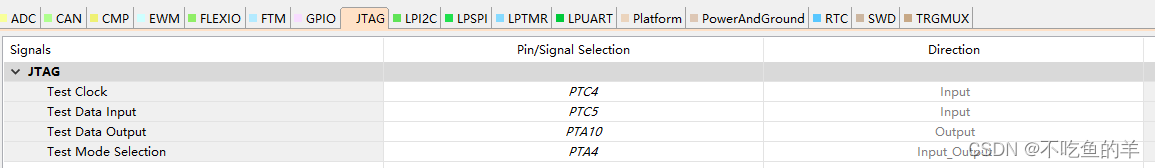
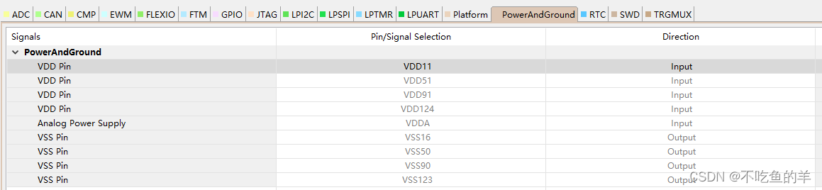
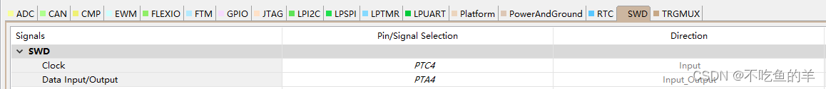
}调试引脚
pin_mux里面除了普通的GPIO以外,还涉及ADC、SPI等其他模块,只要想开这些模块,都是需要先配置GPIO口和时钟的。
链接仿真器或者下载程序的引脚信息也可以参考这里,这样就不用每次都翻芯片手册了。


 5351
5351


 被折叠的 条评论
为什么被折叠?
被折叠的 条评论
为什么被折叠?
 到【灌水乐园】发言


