


让VS支持Shaderlab语法
VS2013中并没有Shaderlab的语法高亮,好在网上已经有个插件来支持语法的高亮和拼写提示,从这里下载插件,双击安装就好了。
ShaderlabVS - https://github.com/wudixiaop/ShaderlabVS/releases
不过由于VS配色的关系,还需要微调一下,按下面步骤
1. 打开 VS -> 工具 -> 选项 -> 环境 -> 字体和颜色,
2. 显示其设置 下拉列表中选择 文本编辑器 (如果没改过,这就是默认的)。
3. 在 显示项(D) 文字下面的列表框中选择以 “Shaderlab-” 开头的项,然后改变前景色
4. 改完后确定就可以了
SubShader 和 Pass
一个Shader有多个SubShader。一个SubShader可理解为一个Shader的一个渲染方案。即SubShader是为了针对不同的显卡而编写的。每个Shader至少1个SubShader、理论可以无限多个,但往往两三个就足够。
SubShader和显卡的兼容性判断,和SubShader的标签、Pass的标签和显卡支持的“Unity渲染路径”有关。显卡会自动选择一个最适合它自身性能的SubShader去执行。
在一个SubShader中我们可以定义多个Pass,而Pass与SubShader不同,你写的每一个Pass都会按照顺序全部执行一遍.我们要在Pass中写具体的着色器代码,还有一点要提一下,在Unity主推的Surface Shader中是不能写Pass的,因为在Unity的光照模型中他会自动定义一些Pass,所以也就不再允许你额外写了。
UV动画
UV动画是通过改变纹理的UV坐标来实现纹理的运动,常用于水流,岩浆等模拟,也能到达很好的模拟效果 ,关键性能消耗非常低。
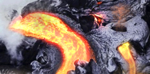
下面以水流模拟为例子。
创建材质,Shader如下,
Shader "Custom/ScrollShader" {
	Properties {
		_MainTint("Diffuse Color", Color) = (1,1,1,1)
		_MainTex ("Base (RGB)", 2D) = "white" {}
		_ScrollXSpeed ("X Scroll Speed", Range(0, 10)) = 2
		_ScrollYSpeed ("Y Scroll Speed", Range(0, 10)) = 2
	}
	SubShader {
		Tags { "RenderType"="Opaque" }
		LOD 200

		CGPROGRAM
		#pragma surface surf Lambert

		sampler2D _MainTex;
		fixed4 _MainTint;
		fixed _ScrollXSpeed;
		fixed _ScrollYSpeed;

		struct Input {
			float2 uv_MainTex;
		};

		void surf (Input IN, inout SurfaceOutput o) {

			fixed2 scrolledUV = IN.uv_MainTex;

			fixed xScrollValue = _ScrollXSpeed * _Time;
			fixed yScrollValue = _ScrollYSpeed * _Time;

			scrolledUV += fixed2(xScrollValue, yScrollValue);

			half4 c = tex2D (_MainTex, scrolledUV);
			o.Albedo = c.rgb * _MainTint;
			o.Alpha = c.a;
		}
		ENDCG
	}
	FallBack "Diffuse"
}
将对应的纹理拖拽到shader上,最终效果如下:
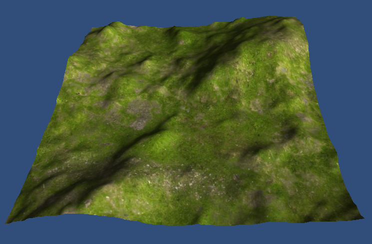
纹理融合
纹理融合常用于地形的纹理。如果没有融合的情况下,只用一张草地的贴图进行绘制,地形是这样的:
将多个纹理进行融合,得到的结果就是这样的:
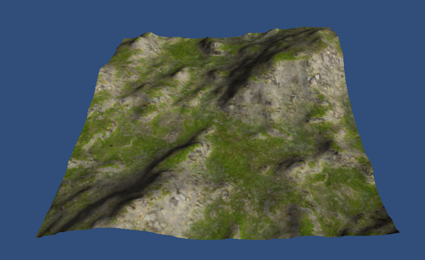
原理也非常简单,首先要准备多张纹理贴图,比如草地,石子,土地等,然后利用一张索引贴图的rgba值来索引融合的比例值。
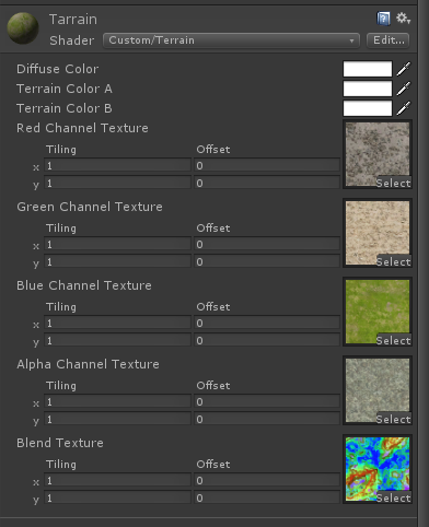
如上图所示,这里用到了四张纹理,最后一张BlendTexture是用于索引融合的比例。编辑的时候只要修改BlendTexuture就能改变地形的纹理了。
shader代码如下
Shader "Custom/Terrain" {
	Properties {
		_MainTint("Diffuse Color", Color) = (1,1,1,1)
		_ColorA ("Terrain Color A", Color) = (1,1,1,1)
		_ColorB ("Terrain Color B", Color) = (1,1,1,1)
		_RTexture ("Red Channel Texture", 2D) = ""{}
		_GTexture ("Green Channel Texture", 2D) = ""{}
		_BTexture ("Blue Channel Texture", 2D) = ""{}
		_ATexture ("Alpha Channel Texture", 2D) = ""{}
		_BlendTexture ("Blend Texture", 2D) = "" {}
	}
	SubShader {
		Tags { "RenderType"="Opaque" }
		LOD 200

		CGPROGRAM
		#pragma surface surf Lambert

		float4 _MainTint;
		float4 _ColorA;
		float4 _ColorB;
		sampler2D _RTexture;
		sampler2D _GTexture;
		sampler2D _BTexture;
		sampler2D _ATexture;
		sampler2D _BlendTexture;

		struct Input {
			float2 uv_RTexture;
			float2 uv_GTexture;
			float2 uv_BTexture;
			float2 uv_ATexture;
			float2 uv_BlendTexture;

		};

		void surf (Input IN, inout SurfaceOutput o) {
			float4 blendData = tex2D(_BlendTexture, IN.uv_BlendTexture);
			float4 rTexData = tex2D(_RTexture, IN.uv_RTexture);
			float4 gTexData = tex2D(_GTexture, IN.uv_GTexture);
			float4 bTexData = tex2D(_BTexture, IN.uv_BTexture);
			float4 aTexData = tex2D(_ATexture, IN.uv_ATexture);


			float4 finalColor;
			finalColor = lerp(rTexData, gTexData, blendData.g);
			finalColor = lerp(finalColor, bTexData, blendData.b);
			finalColor = lerp(finalColor, aTexData, blendData.a);
			finalColor.a = 1.0;

			float4 terrainLayers = lerp(_ColorA, _ColorB, blendData.r);
			finalColor *= terrainLayers;
			finalColor = saturate(finalColor);

			o.Albedo = finalColor.rgb * _MainTint.rgb;
			o.Alpha = finalColor.a;
		}
		ENDCG
	}
	FallBack "Diffuse"
}
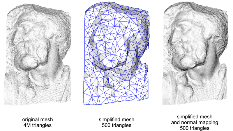
法线贴图
一句话概括,就是在低面数的模型中通过改变表面法线的方法来增加模型的细节度。看一下下面的图就明白了。
由于unity自带的builidin shader,整个计算过程都变得十分简单了。
记得一定要将对应的法线贴图的类型设为Normal Texture。
Shader代码
Shader "Custom/NormalMap" {
	Properties {
		_MainTint("Diffuse Tint", Color) = (1,1,1,1)
		_MainTex ("Base (RGB)", 2D) = "white" {}
		_NormalTex("Normal Map", 2D) = "bump"{}
		_NormalIntensity("Normal Map Intensity", Range(0,2)) = 1
	}
	SubShader {
		Tags { "RenderType"="Opaque" }
		LOD 200

		CGPROGRAM
		#pragma surface surf Lambert

		sampler2D _MainTex;
		sampler2D _NormalTex;
		float _NormalIntensity;
		float4 _MainTint;

		struct Input {
			float2 uv_MainTex;
			float2 uv_NormalTex;
		};

		void surf (Input IN, inout SurfaceOutput o) {
			float3 normalMap = UnpackNormal(tex2D(_NormalTex, IN.uv_NormalTex));
			float4 texColor = tex2D(_MainTex, IN.uv_MainTex);
			normalMap = normalize(float3(normalMap.x * _NormalIntensity, normalMap.y * _NormalIntensity, normalMap.z));
			o.Normal = normalMap.rgb;
			o.Albedo = texColor.rgb * _MainTint.rgb;
			o.Alpha = texColor.a;
		}
		ENDCG
	}
	FallBack "Diffuse"
}
最终效果
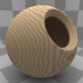
过程纹理
过程纹理就用代码生成的纹理,常用于创造自然元素,如木材,大理石,花岗岩,金属,石材等。通常情况下,所呈现的结果自然的外观是由分形噪声和湍流函数的用法来实现,比如下面这个木纹小球
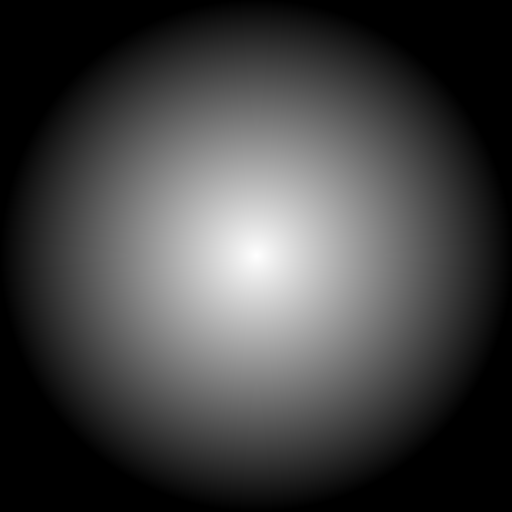
在Unity里面实现的思路也很简单,就是创建 一个Texture2D对象,然后计算每个像素的值,最后将其赋给材质就可以了。核心的绘制方法如下
Texture2D GenerateParabola()
	{
		Texture2D procedualTexture = new Texture2D(widthHeight, widthHeight);
		Vector2 centerPixelPosition = centerPosition * widthHeight;

		for (int x = 0; x < widthHeight; x++)
			for (int y = 0; y < widthHeight; y++)
			{
				Vector2 currentPosition = new Vector2(x, y);
				//Debug.Log("" + currentPosition +" "+ centerPixelPosition);

				float pixelDistance = Vector2.Distance(currentPosition, centerPixelPosition)/(widthHeight*0.5f);
				//Debug.Log("pixelDistance1 " + pixelDistance);

				pixelDistance = Mathf.Abs(1 - Mathf.Clamp(pixelDistance, 0f, 1f));

				Color pixelColor = new Color(pixelDistance, pixelDistance, pixelDistance, 1.0f);

				procedualTexture.SetPixel(x, y, pixelColor);
			}

		procedualTexture.Apply();
		return procedualTexture;
	}
这是简单的生成,生成的纹理是这样的。
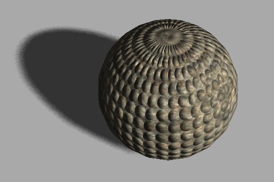
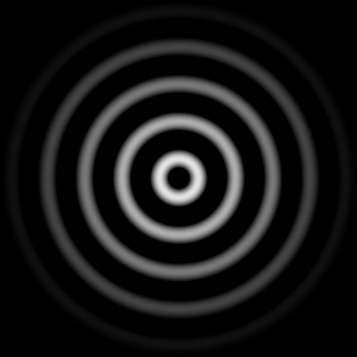
稍微修改一下,将pixelDistence的计算修改为
pixelDistance = (Mathf.Sin(pixelDistance * 30.0f) * pixelDistance);
可以生成的纹理如下
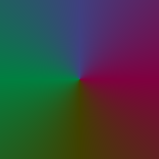
最后再改一下
Vector2 pixelDirection = centerPixelPosition - currentPosition;
pixelDirection.Normalize();
float rightDirection = Vector2.Angle(pixelDirection, Vector3.right) / 360;
float leftDirection = Vector2.Angle(pixelDirection, Vector3.left) / 360;
float upDirection = Vector2.Angle(pixelDirection, Vector3.up) / 360;

Color pixelColor = new Color(rightDirection, leftDirection, upDirection, 1.0f);
得到的纹理如下
用下面的代码可以将生成的纹理dump下来。
			var bytes = generatedTexture.EncodeToPNG();
			File.WriteAllBytes(Application.dataPath + "/../SavedScreen.png", bytes);
参考
法线贴图 - http://zh.wikipedia.org/wiki/%E6%B3%95%E7%BA%BF%E8%B4%B4%E5%9B%BE
Unity Shaders and Effects Cookbook


 394
394

 被折叠的 条评论
为什么被折叠?
被折叠的 条评论
为什么被折叠?
 到【灌水乐园】发言


